Installation Guide_PV-ezRack_SolarTerraceII-A_AU_V2.0
1/10 Duerdin Street, Clayton VIC 3168 Australia
Tel: +61 3 9239 8088 Fax: +61 3 9239 8024
E-mail: sales@clenergy.com.au www.clenergy.com.au
01page of 21
Introduction
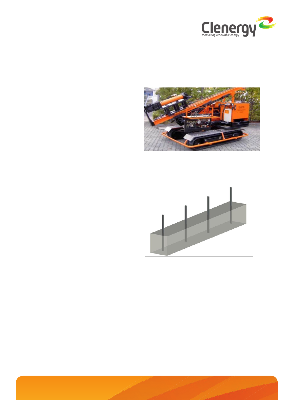
Clenergy PV-ezRack®SolarTerrace II-A™ is a
pre-assembled ground mount system suitable
for large scale commercial and utility scale
installations. PV-ezRackSolarTerrace II-A has
been developed to fit any PV module. The
innovative and patented SolarTerrace II-A
T-Rails simplify and improve the accuracy
of the installation. SolarTerrace II-A uses
high quality engineered components, saving
developers and installers’ time and money
when delivering ground mount projects.
Please review this instruction guide thoroughly
before installing PV-ezRackSolarTerrace II-
A. This manual provides the supporting
documentation for building permit applications
relating to PV-ezRackSolarTerrace II-A
Universal PV Mounting System.
The PV-ezRackSolarTerrace II-A components,
when installed in accordance with this guide,
will be structurally adequate and will meet the
AS/NZS1170.2:2011 Amdt. 3-2012 standard.
During installation and especially when working
on the ground, you will need to comply with
the appropriate occupational health and safety
regulations. Please also check other regulations
relevant to your local region. Make sure that you
are using the latest version of the installation
instruction guide, which you can do by
contacting Clenergy by email on sales@clenergy.
com.au, or contacting your local distributor.
The installer is solely responsible for:
•Complying with all applicable local or national
building codes, including any that may
supersede this manual;
•Ensuring that ezRack and other products are
appropriate for the particular installation and the
installation environment;
•Using only ezRack parts and installer-supplied
parts as specified by ezRack (substitution of
parts may void the warranty and invalidate the
letter of certification);
•Ensuring that the ground condition are suitable;
•How to recycle: according to the local relative
statute.
•How to disassemble: reverse installation
process.
•Ensure that there are no less than two
professionals working on the panel installation.
•Ensure the installation of the electrical
equipment is performed by a professional and
accredited electrician.
•Ensuring safe installation of all electrical aspects
of the PV array including providing adequate
earth bonding of the PV array and PV-ezRack®
SolarTerraceII-A™components as required in AS/
NZS 5033-2014 ADMT 2 2-2018.
Introduction
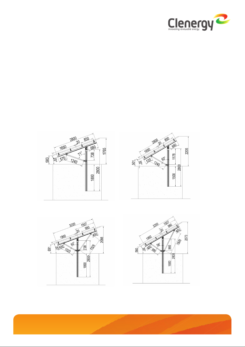
Planning
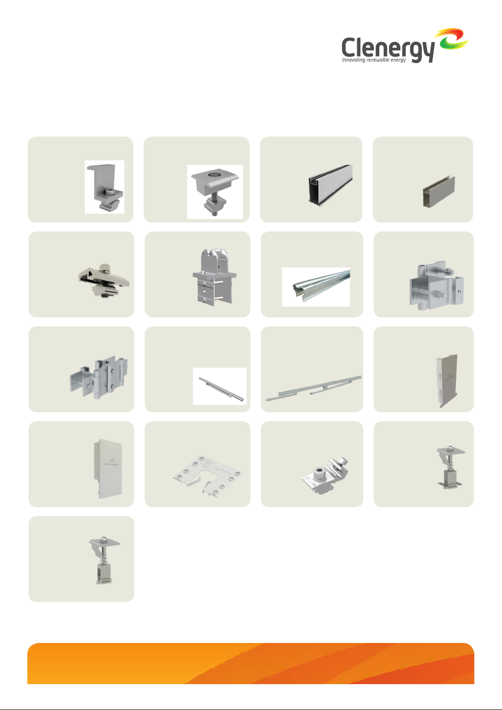
Tools & Components
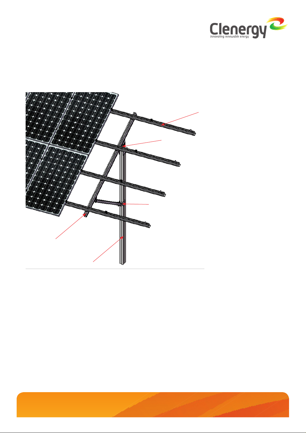
System Overview
Installation Instruction
Warranty
01
02
04
06
08
21
List of Contents
1. Introduction