Clevo P170HM User manual


Preface
V
Preface
Instructions for Care and Operation
The notebook computer is quite rugged, but it can be damaged. To prevent this, follow these suggestions:
1. Don’t drop it, or expose it to shock. If the computer falls, the case and the components could be damaged.
2. Keep it dry, and don’t overheat it. Keep the computer and power supply away from any kind of heating element. This
is an electrical appliance. If water or any other liquid gets into it, the computer could be badly damaged.
3. Follow the proper working procedures for the computer. Shut the computer down properly and don’t forget to save
your work. Remember to periodically save your data as data may be lost if the battery is depleted.
Do not expose the computer
to any shock or vibration.
Do not place it on an unstable
surface.
Do not place anything heavy
on the computer.
Do not expose it to excessive
heat or direct sunlight.
Do not leave it in a place
where foreign matter or mois-
ture may affect the system.
Don’t use or store the com-
puter in a humid environment.
Do not place the computer on
any surface which will block
the vents.
Do not turn off the power
until you properly shut down
all programs.
Do not turn off any peripheral
devices when the computer is
on.
Do not disassemble the com-
puter by yourself.
Perform routine maintenance
on your computer.

Preface
VI
Preface
4. Avoid interference. Keep the computer away from high capacity transformers, electric motors, and other strong mag-
netic fields. These can hinder proper performance and damage your data.
5. Take care when using peripheral devices.
Power Safety
The computer has specific power requirements:
• Only use a power adapter approved for use with this computer.
• Your AC adapter may be designed for international travel but it still requires a steady, uninterrupted power supply. If you are
unsure of your local power specifications, consult your service representative or local power company.
• The power adapter may have either a 2-prong or a 3-prong grounded plug. The third prong is an important safety feature; do
not defeat its purpose. If you do not have access to a compatible outlet, have a qualified electrician install one.
• When you want to unplug the power cord, be sure to disconnect it by the plug head, not by its wire.
• Make sure the socket and any extension cord(s) you use can support the total current load of all the connected devices.
• Before cleaning the computer, make sure it is disconnected from any external power supplies.
Use only approved brands of
peripherals.
Unplug the power cord before
attaching peripheral devices.
Do not plug in the power
cord if you are wet.
Do not use the power cord if
it is broken.
Do not place heavy objects
on the power cord.
Power Safety
Warning
Before you undertake
any upgrade proce-
dures, make sure that
you have turned off the
power, and discon-
nected all peripherals
and cables (including
telephone lines). It is
advisable to also re-
move your battery in
order to prevent acci-
dentally turning the
machine on.

Preface
VII
Preface
Battery Precautions
• Only use batteries designed for this computer. The wrong battery type may explode, leak or damage the computer.
• Do not continue to use a battery that has been dropped, or that appears damaged (e.g. bent or twisted) in any way. Even if the
computer continues to work with a damaged battery in place, it may cause circuit damage, which may possibly result in fire.
• Recharge the batteries using the notebook’s system. Incorrect recharging may make the battery explode.
• Do not try to repair a battery pack. Refer any battery pack repair or replacement to your service representative or qualified service
personnel.
• Keep children away from, and promptly dispose of a damaged battery. Always dispose of batteries carefully. Batteries may explode
or leak if exposed to fire, or improperly handled or discarded.
• Keep the battery away from metal appliances.
• Affix tape to the battery contacts before disposing of the battery.
• Do not touch the battery contacts with your hands or metal objects.
Battery Guidelines
The following can also apply to any backup batteries you may have.
• If you do not use the battery for an extended period, then remove the battery from the computer for storage.
• Before removing the battery for storage charge it to 60% - 70%.
• Check stored batteries at least every 3 months and charge them to 60% - 70%.
Battery Disposal
The product that you have purchased contains a rechargeable battery. The battery is recyclable. At the end of its useful life, under var-
ious state and local laws, it may be illegal to dispose of this battery into the municipal waste stream. Check with your local solid waste
officials for details in your area for recycling options or proper disposal.
Caution
Danger of explosion if battery is incorrectly replaced. Replace only with the same or equivalent type recommended by the manufacturer.
Discard used battery according to the manufacturer’s instructions.
Battery Level
Click the battery icon in the taskbar to see the current battery level and charge status. A battery that drops below a level of 10%
will not allow the computer to boot up. Make sure that any battery that drops below 10% is recharged within one week.

Preface
VIII
Preface
Related Documents
You may also need to consult the following manual for additional information:
User’s Manual on Disc
This describes the notebook PC’s features and the procedures for operating the computer and its ROM-based setup pro-
gram. It also describes the installation and operation of the utility programs provided with the notebook PC.
System Startup
1. Remove all packing materials.
2. Place the computer on a stable surface.
3. Insert the battery and tighten the screws.
4. Securely attach any peripherals you want to use with the computer (e.g.
keyboard and mouse) to their ports.
5. Attach the AC/DC adapter to the DC-In jack at the rear of the computer, then
plug the AC power cord into an outlet, and connect the AC power cord to the AC/
DC adapter.
6. Use one hand to raise the lid/LCD to a comfortable viewing angle (do not to
exceed 130 degrees);
use the other hand (as illustrated in <Hyperlink B n
I>Figure 1) to support the base of the computer (Note: Never lift the computer by
the lid/LCD).
7. Press the power button to turn the computer “on”.
130 ゚
Figure 1
Opening the Lid/LCD/
Computer with AC/DC
Adapter Plugged-In

Introduction
1 - 2 Overview
1.Introduction
Specifications
Latest Specification Information
The specifications listed here are correct at the
time of sending them to the press. Certain items
(particularly processor types/speeds) may be
changed, delayed or updated due to the manu-
facturer's release schedule. Check with your
service center for more details.
CPU
The CPU is not a user serviceable part. Ac-
cessing the CPU in any way may violate your
warranty.
Processor Options
Intel® Core™ i7 Processor Extreme Edition
i7-2920XM (2.50GHz)
8MB L3 Cache, 32nm, DDR3-1600MHz, TDP 55W
Intel® Core™ i7 Processor
i7-2820QM (2.30GHz)
8MB L3 Cache, 32nm, DDR3-1600MHz, TDP 45W
i7-2720QM (2.20GHz) , i7-2630QM (2.0GHz)
6MB L3 Cache, 32nm, DDR3-1600MHz, TDP 45W
i7-2520M (2.50GHz)
3MB L3 Cache, 32nm, DDR3-1333MHz, TDP 35W
Memory
*Four 204 Pin SO-DIMM Sockets Supporting DDR3 1333/
1600** MHz Memory Modules
Memory Expandable up to 16GB
Compatible with 2GB or 4GB Modules
*Note: Four SO-DIMMs are only supported by Quad-Core
CPUs; Dual-Core CPUs support two SO-DIMMs maximum
**Note:
1600 MHz Memory Modules
are only supported by
Quad-Core CPUs to a maximum of two SO-DIMMs
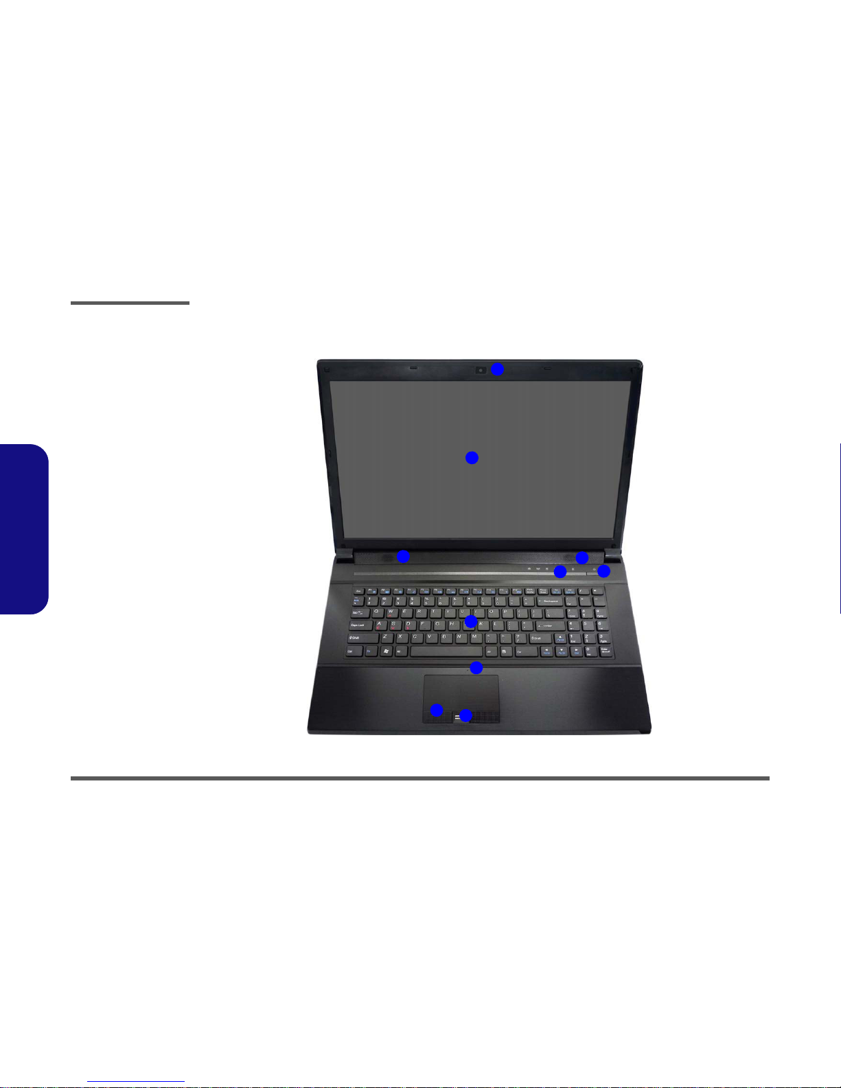
LCD
17.3" (43.94cm) FHD (1920 * 1080)
BIOS
AMI BIOS (32Mb SPI Flash-ROM)
Storage
(Factory Option) One Changeable 12.7mm(h) Optical Device
Type Drive (Super Multi Drive Module or Blu-Ray Combo Drive
Module)
Two Changeable 2.5" 9.5 mm (h) SATA (Serial) Hard Disk
Drives supporting RAID level 0/1/Recovery
Security
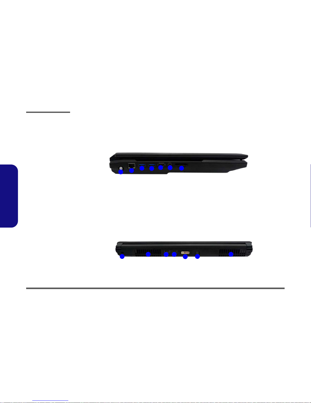
Security (Kensington® Type) Lock Slot
BIOS Password
(Factory Option) Fingerprint Reader Module
Core Logic
Intel® HM67 Chipset
Video Adapter
nVIDIA® GeForce GTX 485M PCIe Video Card
2GB GDDR5 Video RAM on board
Microsoft DirectX® 11 Compatible
nVIDIA® GeForce GTX 470M PCIe Video Card
1.5GB GDDR5 Video RAM on board
Microsoft DirectX® 11 Compatible
nVIDIA® GeForce GTX 460M PCIe Video Card
1.5GB GDDR5 Video RAM on board
Microsoft DirectX® 11 Compatible
Audio
High Definition Audio Compliant Interface
THX TruStudio Pro
S/PDIF Digital Output
One (3W) Sub Woofer
Built-In Microphone
5 Speakers
Pointing Device
Built-in TouchPad (scrolling key functionality integrated)
Keyboard
Full-size “WinKey” keyboard with numeric keypad
Communication
Built-In Giga Base-TX Ethernet LAN
2.0M Pixel USB PC Camera Module
(Factory Option) TV Tuner Mini-Card Module (Model C Only)
(Factory Option) Intel® WiFi Link 6230 (802.11a/g/n) Wire-
less LAN + Bluetooth 3.0 Half Mini-Card Combo Module
(Factory Option) Intel® WiFi Link 6300 (802.11a/g/n) Wire-
less LAN Half Mini-Card Module
(Factory Option) Third-Party Wireless LAN (802.11b/g/n) +
Bluetooth 3.0 Half Mini-Card Combo Module
(Factory Option) Third-Party 802.11b/g/n Wireless LAN Half
Mini-Card Module
Card Reader
Embedded Multi-In-1 Card Reader
MMC (MultiMedia Card) / RS MMC
SD (Secure Digital) / Mini SD / SDHC/ SDXC
MS (Memory Stick) / MS Pro / MS Duo

Introduction
Overview 1 - 3
1.Introduction
Interface
Two USB 3.0 Ports
Two USB 2.0 Ports (Note one USB 2.0 port can supply power
when the system is off but still powered by the AC/DC adapter
- see page 11.)
One eSATA & USB 2.0 Combo Port
One HDMI-Out Port
One DVI-Out Port
One IEEE1394a Port
One S/PDIF-Out & Surround-Out Combo Jack
One Headphone/Speaker-Out Jack
One Microphone-In Jack
One Line-In Jack
One RJ-45 LAN
Jack
One DC-In Jack
One Infrared Receiver for Optional TV Tuner Remote Control
One CATV Antenna Jack (for Optional TV Tuner)
Note: External 7.1CH Audio Output Supported by Headphone,
Microphone, Line-In and Surround-Out Jacks
Mini Card Slots
Slot 1 for WLAN Module or Combo WLAN and Bluetooth
Module
(Factory Option) Slot 2 for TV Tuner Module
Environmental Spec
Temperature
Operating: 5°C - 35°C
Non-Operating: -20°C - 60°C
Relative Humidity
Operating: 20% - 80%
Non-Operating: 10% - 90%
Power
Removable 8-cell cylinder battery, 76.96Wh (5200mAh)
Full Range AC/DC Adapter
AC Input: 100 - 240V, 50 - 60Hz
DC Output: 19V, 11.57A (220W)
Dimensions & Weight
412mm (w) * 276mm (d) * 41.8-45.4mm (h)
Around 3.9kg with Battery and ODD

Introduction
1 - 4 External Locator - Top View with LCD Panel Open
1.Introduction
External Locator - Top View with LCD Panel Open
Figure 1
Top View
1. PC Camera
2. LCD
3. LED Status
Indicators
4. Power Button
5. Speakers
6. Keyboard
7. Built-In
Microphone
8. TouchPad and
Buttons
9. Fingerprint
Reader (Optional)
3
2
1
89
7
6
5
4
5
3

Introduction
External Locator - Front & Right side Views 1 - 5
1.Introduction
External Locator - Front & Right side Views
Figure 2
Front Views
1. Consumer
Infrared Receiver
2. LED Indicators
Figure 3
Right Side Views
1. Optical Device
Drive Bay
2. Headphone Jack
3. Microphone Jack
4. S/PDIF-Out Jack
5. Line-In Jack
6. 1 * USB 2.0 Port
12
Right
13 42 65

Introduction
1 - 6 External Locator - Left Side & Rear View
1.Introduction
External Locator - Left Side & Rear View
Figure 4
Left Side View
1. RJ-45 LAN Jack
2. 2 * USB 3.0 Ports
3. 1 * USB 2.0 Port
4. Mini-IEEE 1394a
Port
5. Multi-in-1 Card
Reader
6. CATV Antenna
Jack
12345
2
6
Figure 5
Rear View
1. Vent/Fan Intake
2. eSATA/USB 2.0
Combo Port
3. HDMI-Out Port
4. DVI-Out Port
5. DC-In Jack
6. Security Lock Slot
235
141
6

Introduction
External Locator - Bottom View 1 - 7
1.Introduction
External Locator - Bottom View
Figure 6
Bottom View
1. Sub Woofer
2. Fan Outlet/Intake
3. Component Bay
Cover
4. Primary HDD Bay
5. Secondary HDD
Bay
6. Battery
7. Speakers
Overheating
To prevent your com-
puter from overheating
make sure nothing
blocks the vent/fan in-
takes while the com-
puter is in use.
12
4
5
3
22
2
6
7667
7

Disassembly
2 - 2 Overview
2.Disassembly
NOTE: All disassembly procedures assume that the system is turned OFF, and disconnected from any power supply (the
battery is removed too).
Maintenance Tools
The following tools are recommended when working on the notebook PC:
• M3 Philips-head screwdriver
• M2.5 Philips-head screwdriver (magnetized)
• M2 Philips-head screwdriver
• Small flat-head screwdriver
• Pair of needle-nose pliers
• Anti-static wrist-strap
Connections
Connections within the computer are one of four types:
Locking collar sockets for ribbon connectors To release these connectors, use a small flat-head screwdriver to
gently pry the locking collar away from its base. When replac-
ing the connection, make sure the connector is oriented in the
same way. The pin1 side is usually not indicated.
Pressure sockets for multi-wire connectors To release this connector type, grasp it at its head and gently
rock it from side to side as you pull it out. Do not pull on the
wires themselves. When replacing the connection, do not try to
force it. The socket only fits one way.
Pressure sockets for ribbon connectors To release these connectors, use a small pair of needle-nose pli-
ers to gently lift the connector away from its socket. When re-
placing the connection, make sure the connector is oriented in
the same way. The pin1 side is usually not indicated.
Board-to-board or multi-pin sockets To separate the boards, gently rock them from side to side as
you pull them apart. If the connection is very tight, use a small
flat-head screwdriver - use just enough force to start.

Disassembly
Overview 2 - 3
2.Disassembly
Maintenance Precautions
The following precautions are a reminder. To avoid personal injury or damage to the computer while performing a re-
moval and/or replacement job, take the following precautions:
1. Don't drop it. Perform your repairs and/or upgrades on a stable surface. If the computer falls, the case and other
components could be damaged.
2. Don't overheat it. Note the proximity of any heating elements. Keep the computer out of direct sunlight.
3. Avoid interference. Note the proximity of any high capacity transformers, electric motors, and other strong mag-
netic fields. These can hinder proper performance and damage components and/or data. You should also monitor
the position of magnetized tools (i.e. screwdrivers).
4. Keep it dry. This is an electrical appliance. If water or any other liquid gets into it, the computer could be badly
damaged.
5. Be careful with power. Avoid accidental shocks, discharges or explosions.
•Before removing or servicing any part from the computer, turn the computer off and detach any power supplies.
•When you want to unplug the power cord or any cable/wire, be sure to disconnect it by the plug head. Do not pull on the wire.
6. Peripherals – Turn off and detach any peripherals.
7. Beware of static discharge. ICs, such as the CPU and main support chips, are vulnerable to static electricity.
Before handling any part in the computer, discharge any static electricity inside the computer. When handling a
printed circuit board, do not use gloves or other materials which allow static electricity buildup. We suggest that
you use an anti-static wrist strap instead.
8. Beware of corrosion. As you perform your job, avoid touching any connector leads. Even the cleanest hands pro-
duce oils which can attract corrosive elements.
9. Keep your work environment clean. Tobacco smoke, dust or other air-born particulate matter is often attracted
to charged surfaces, reducing performance.
10. Keep track of the components. When removing or replacing any part, be careful not to leave small parts, such as
screws, loose inside the computer.
Cleaning
Do not apply cleaner directly to the computer, use a soft clean cloth.
Do not use volatile (petroleum distillates) or abrasive cleaners on any part of the computer.
Power Safety
Warning
Before you undertake
any upgrade proce-
dures, make sure that
you have turned off the
power, and discon-
nected all peripherals
and cables (including
telephone lines). It is
advisable to also re-
move your battery in
order to prevent acci-
dentally turning the
machine on.

Disassembly
Removing the Battery 2 - 5
2.Disassembly
Removing the Battery
1. Turn the computer off, and turn it over.
2. Slide the latch in the direction of the arrow (Figure 1a).
3. Slide the latch in the direction of the arrow, and hold it in place (Figure 1a).
4. Lift the battery out in the direction of the arrow (Figure 1b & Figure 1c).
3. Battery
1
2
6
3
4
a.
b.
21
3
4
c.
3
Figure 1
Battery Removal
a. Slide the latch and hold in
place.
b. Slide the battery in the di-
rection of the arrow.
c. Lift the battery out in the
direction of the arrow.

Disassembly
2 - 6 Removing the Hard Disk Drive
2.Disassembly
Removing the Hard Disk Drive
The hard disk drive can be taken out to accommodate other 2.5" serial (SATA) hard disk drives with a height of 9.5mm
(h). Follow your operating system’s installation instructions, and install all necessary drivers and utilities (as outlined in
Chapter 4 of the User’s Manual) when setting up a new hard disk.
Hard Disk Upgrade Process
1. Turn off the computer, and remove the battery (page 2 - 5).
2. Locate the hard disk bay cover and remove screws - (Figure 2a).
3. Remove the hard disk bay cover by levering the cover at point (Figure 2b).
Figure 2
HDD Assembly
Removal
a. Locate the HDD bay
cover and remove the
screws.
b. Remove the hard disk
bay cover by levering the
cover at point .
3
4.Hard Disk Bay Cover
•2Screws
1
2
6
4
3
a.
HDD System Warning
New HDD’s are blank. Before you begin make sure:
You have backed up any data you want to keep from your old HDD.
You have all the CD-ROMs and FDDs required to install your operating system and programs.
If you have access to the internet, download the latest application and hardware driver updates for the operating system you plan
to install. Copy these to a removable medium.
3
1
2
b.
3
4

Disassembly
Removing the Hard Disk Drive 2 - 7
2.Disassembly
4. Slide the HDD assembly in the direction of the arrow (Figure 3c).
5. Remove the hard disk assembly (Figure 3d).
6. Remove screws & and the insulation plate (Figure 3e).
7. Reverse the process to install a new hard disk (do not forget to replace all the screws and covers).
4
6
5
6
7
6
8
c. d.
5
6
4
7
e.
8
5. HDD
8. HDD Insulation Plate
•2Screws
Figure 3
HDD Assembly
Removal (cont’d.)
c. Slide the HDD assembly
in the direction of the ar-
row.
d. Remove the hard disk
assembly.
e. Remove the screws and
the insulation plate.

Disassembly
2 - 8 Inserting the Hard Disk Into the HDD Bay
2.Disassembly
Inserting the Hard Disk Into the HDD Bay
1. Make sure the HDD assembly is aligned with the black taped area (Figure 4a).
2. When aligned, carefully insert the HDD assembly into the case so that the connectors line up (Figure 4a).
3. Replace the hard disk bay covers and screws.
2. HDD
Figure 4
Inserting the Hard
Disk Into the HDD
Bay
a. Make sure the HDD as-
sembly is aligned with the
black taped area. When
aligned, carefully insert
the HDD assembly into
the case so that the con-
nectors line up.
1
6
2
1
1
a.
2

Disassembly
Removing the Optical (CD/DVD) Device 2 - 9
2.Disassembly
Removing the Optical (CD/DVD) Device
1. Turn off the computer, and remove the battery (page 2 - 5).
2. Locate the secondary hard disk bay cover and remove screws & (Figure 5a).
3. Remove the hard disk bay cover (Figure 5b).
4. Remove the screw at point (Figure 5c), and use a screwdriver to carefully push out the optical device out of
the bay at point (Figure 5d).
5. Reverse the process to install any new optical (CD/DVD) device.
Figure 5
Optical Device
Removal
a. Locate the secondary
hard disk bay cover and
remove the screws.
b. Remove the cover.
c. Remove the screw.
d. Push the optical device
out off the computer at
point 6.
1
2
6
3
4
6
5
6
3. Secondary HDD Bay
Cover
5. Optical Device
•3Screws
1
2
4
3
6
5
a. c.
d.b.

Disassembly
2 - 10 Removing the Hard Disk from the Secondary HDD Bay
2.Disassembly
Removing the Hard Disk from the Secondary HDD Bay
Note that the secondary hard disk (if installed) is located under the optical device bay (CD/DVD).
1. Turn off the computer, and turn it over, remove the battery (page 2 - 5) and optical device (page 2 - 9).
2. Remove screws - from the secondary HDD assembly (Figure 6a).
3. Slide the secondary HDD assembly in the direction of the arrow (it will not move fully out of the bay Figure 6a).
4. Lift the secondary HDD assembly up and out of the bay (in the reverse direction of the arrow Figure 6c).
5. Hard Disk Assembly
•3Screws
Figure 6
Secondary HDD
Assembly Removal
a. Remove the screws from
the secondary HDD as-
sembly.
b. Slide the secondary HDD
assembly in the direction
of the arrow.
c. Lift the secondary HDD
assembly up and out of
the bay.
1
3
4
6
5
4
a. c.
b.
3
12
4
5
5

Disassembly
Removing the Hard Disk from the Secondary HDD Bay 2 - 11
2.Disassembly
5. Remove screws - and the insulation plate (Figure 7d).
6. Reverse the process to install a new disk (make sure you install the insulation plate).
7. Slide the HDD assembly into the bay at an angle as illustrated.
8. Make sure the insulation plate slides under the HDD bay guide at point .
9. Slide the assembly in the direction of the arrow and secure the assembly with the screws.
Figure 7
Secondary HDD
Assembly Removal
d. Remove the screws and
the insulation plate.
10. HDD Insulation Plate
•4Screws
6
9
10
9
7
6
8
d.
10
11
12
9
7
8
11
12
Other manuals for P170HM
1
Table of contents
Other Clevo Laptop manuals