CLIMAVENETA i-LIFE SLIM 102 Operating instructions

Fan coil with casing or for built-in
installation, with tangential fan and
inverter controlled brushless motor
EN
i-LIFE SLIM 102÷502
INSTALLATION - USER - MAINTENANCE MANUAL

2i-LIFE SLIM EN 05/2013
U I A
User
Installer
Assistance
Important
rohibition
Danger voltage
Danger high temperatures
CONTENTS U I A
The following symbols are used in this publication and inside the unit:
U
I
A
General warnings 3
Fundamental safety rules 3
Product range 4
Rated technical specifications 4
Overall dimensions 4
Packaging 5
Storage on site 5
nstallation - Positioning the unit 6
nstallation procedure 6
Minimum installation clearance 6
Dismantling/assembling the casing 7
Vertical installation 7
Horizontal installation 8
Fixing the front intake grill 8
Front grill safety support assembly 9
Water connections 10
Condensate drain 10
Filling the system 11
Venting air when filling the system 11
Electrical connections 12
Maintenance 12
Cleaning the outside of the unit 12
Cleaning the air intake filter 12
Tips on saving energy 14
Troubleshooting 14
Troubleshooting table 14
AI
AI
AI
AI
AI
AI
AI
AI
AI
AU
AU
U
U
I A
I A
U I A
I A
I
I A
I A
I A
I A
I A
I A
I A
I A
I A
I A

3EN 05/2013 i-LIFE SLIM
FUNDAMENTAL SAFETY RULES U I A
When operating equipment involving the use of electricity and water, a number of fundamental safety rules must be observed,
namely:
The appliance is not intended for use by persons (includ-
ing children) with reduced physical, sensory or mental
capabilities, or lack of experience and knowledge, unless
they have been given supervision or instruction concern-
ing use of the appliance by a person responsible for their
safety.
Children must be supervised to ensure they do not play
with the appliance.
nstallation must only be performed by qualified person-
nel.
Do not touch the unit with bare feet or with wet or damp
parts of the body.
Never perform any cleaning operations before having
disconnected the unit from the mains power supply,
moving the main switch to the “off” position.
Do not modify safety or control devices without authori-
sation and instructions from the manufacturer.
Do not pull, detach or twist the electrical cables coming
from the unit, even when disconnected from the mains
electricity supply.
Do not introduce objects or substances through the air
outlet and intake grills.
Do not open doors or panels providing access to the
internal parts of the appliance, without first having
moved the main switch to “off”.
Do not dispose of, abandon or leave within reach of chil-
dren packaging materials, as they may represent a haz-
ard.
Do not sit or stand on the appliance and/or rest any type
of object on top of it.
The outside components of the appliance may reach
temperatures exceeding 70°
GENERAL WARNINGS
After having removed the packing, check that the con-
tents are intact and complete.
n the event of discrepancies, contact the service centre
that sold the appliance.
The appliances must be installed by authorised personnel,
who at the end of the work shall issue a declaration of
conformity in compliance with the legislation in force and
with the instructions provided in the booklet supplied with
the appliance.
These appliances have been designed for cooling and
heating rooms and must be used in applications compat-
ible with their performance characteristics.
ncorrect installation, adjustment and maintenance or
improper use absolve the manufacturer from all liability,
whether contractual or otherwise, for damage to people,
animals or things.
n the event of water leaks, move the main system switch
to the “off” position and close the water taps.
Contact the technical service or a qualified professional
as soon as possible. Do not attempt to repair the appli-
ance yourself.
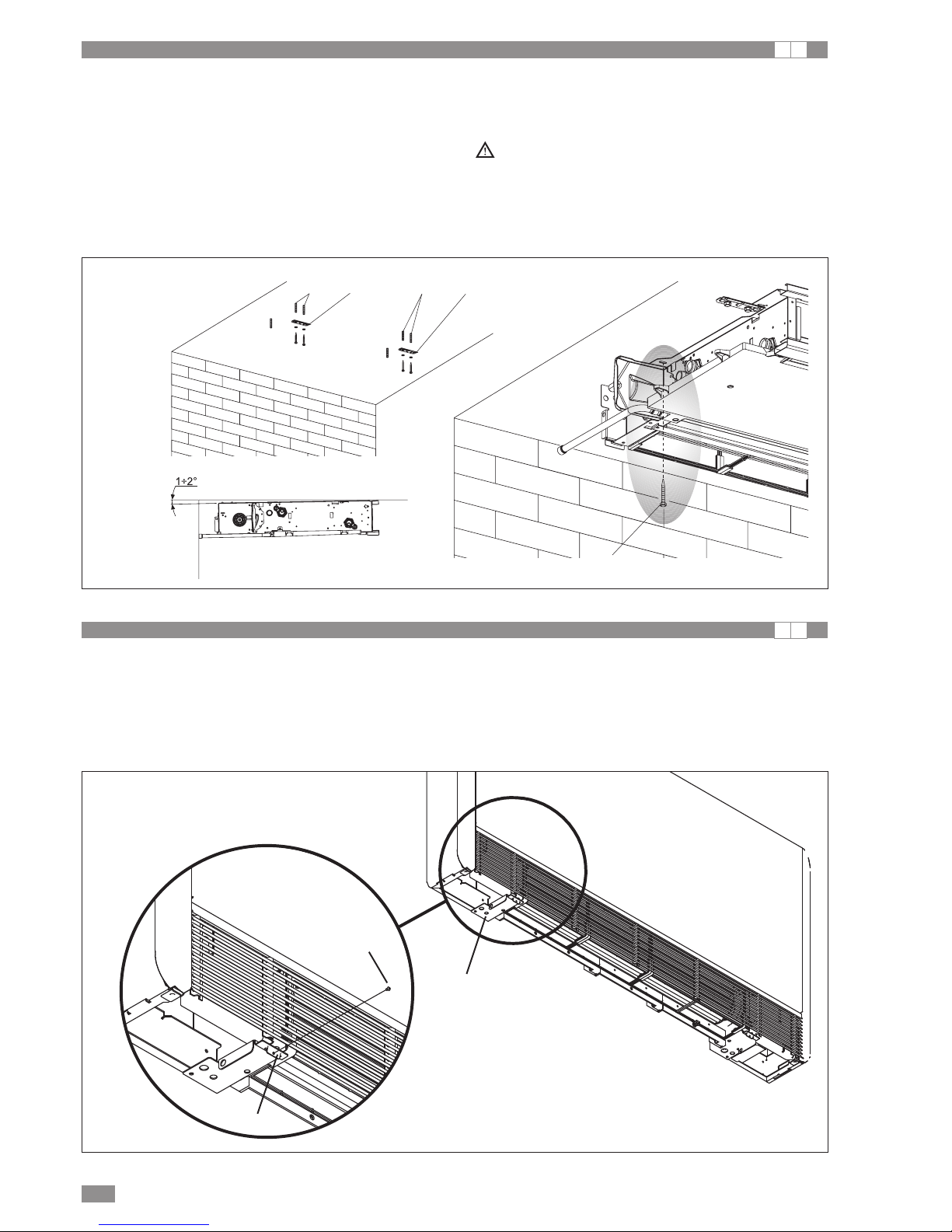
Built-in fan coils are supplied without grills and casing.
Protective covers and air outlet/intake grills must be pro-
vided, to prevent accidental contact with the appliance.
The fan coils with casing are equipped with automatically
adjustable air outlet louvers. For correct operation of the
louvers both when opening and closing, make sure there
is nothing that impedes their movement. For trou-
bleshooting information, see the corresponding chapter.
f the appliance is not used for a long period, proceed as
follows:
- Move the main system switch to the “off” position
- Close the water taps
- f there is the risk of freezing, empty the system or
make sure it antifreeze is added.
Excessively low or high temperatures are harmful to the
health and a useless waste of energy.
Avoid extended direct contact with the air flow.
Do not leave the rooms closed for too long.
Periodically open windows to ensure correct air change.
This instruction booklet is an integral part of the appliance
and must therefore be kept carefully and must ALWAYS
accompany the appliance if sold to another owner or user,
or transferred to another system.
f this booklet is lost or damaged, contact your local Tech-
nical Service for a replacement.
All repair or maintenance work must be carried out by
the company's Technical Service or qualified personnel,
following the instructions in this booklet. Do not modify or
tamper with the appliance as this may create situations
of danger; in such cases the manufacturer of the appli-
ance is not liable for any damage caused.
Pay careful attention to avoiding contact: danger of burns.
U I A

4i-LIFE SLIM EN 05/2013
RODUCT RANGE U I A
The i-L FE SL M range of fan coils comprises 4 versions,
DL U, DLMV, DLMO and DLRV, each of which available in
five sizes, with different performance and overall dimen-
sions.
i-LIFE SLIM DLMV
fan coil with painted metal casing (suitable for vertical instal-
lation)
i-LIFE SLIM DLMO
fan coil with painted metal casing (suitable for horizontal
installation)
i-LIFE SLIM DLIU
built-in fan coil without panelling (suitable for built-in horizon-
tal or vertical installations)
i-LIFE SLIM DLRV
fan coil with painted metal casing with radiant effect (suit-
able for vertical installation only)
I A
RATED TECHNICAL S ECIFICATIONS I A
TECHNICAL S ECIFICATIONS
i-LIFE SLIM
102 202 302 402 502
Coil water content l 0,47 0,8 1,13 1,46 1,8
Maximum operating pressure bar 10 10 10 10 10
Maximum water inlet temperature °C 80 80 80 80 80
Minimum water inlet temperature °C 44444
Water connections * “ Eurokonus 3/4 Eurokonus 3/4 Eurokonus 3/4 Eurokonus 3/4 Eurokonus 3/4
Power supply voltage V/ph/Hz 230/1/50 230/1/50 230/1/50 230/1/50 230/1/50
Maximum current draw, DL U, DLMV and DLMO A 0,15 0,24 0,28 0,29 0,30
Maximum power consumption, DL U, DLMV and DLMO
W 18 27 35 35 37
Weight, DL U kg 9 12 15 18 21
Weight, DLMV and DLMO kg 17 20 23 26 29
Weight, DLRV kg 17,3 20,4 23,4 26,4 29,4
i-LIFE SLIM DLMV, DLMO, DLRV fan coils with casing
Dimensions
102 202 302 402 502
A mm 720 920 1120 1320 1520
* kit supplied as standard containing a pair of adapters for flat gaskets, for 3/4” fittings
OVERALL DIMENSIONS I
659
579
A131
131

5EN 05/2013 i-LIFE SLIM
i-LIFE SLIM DLIU built-in fan coil
Dimensions
102 202 302 402 502
A mm 525 725 925 1125 1325
OVERALL DIMENSIONS I
126
590
A 63,5
47
80
ACKAGING I A
The units are delivered in standard packaging comprising a
cardboard box on pallets; the accessories are supplied sep-
arately, unassembled, or already fitted on the unit (upon
request).
DATI COSTRUTTORE (società costruttrice):
COSTRUTTORE S.R.L. – VIA XY – INDIRIZZOXY – CITTA’XY
Modello della macchina XYZ-XYZ
Codice di identificazione 00123/01/2001
MODELLO 10 20 30 40 50 60 70
Potenza frigorifera kW 12 15 17 34 56 77 84
Potenza termica KW 23 33 43 53 63 65 90
Portata aria mc 330 550 670 750 770 850 910
Assorbimento elettrico W 18 20 45 90 120 150 150
Corrente assorbita A 1 2 2 3 3 4 4
Data di produzione
15 / 10 / 2001
Lotto di produzione
1937 / 2001
nside the unit is an envelope containing the user, installa-
tion and maintenance manual. An identification label is
affixed to each individual unit, describing:
• Manufacturer’s details
• Model of the unit and part/serial number
• Wiring diagrams
STORAGE ON SITE I A
The units must be stored indoors!

6i-LIFE SLIM EN 05/2013
MINIMUM INSTALLATION CLEARANCE I A
The figure illustrates the minimum clearance to be left from
walls and furniture in the room when assembling the fan coil.
INSTALLATION - OSITIONING THE UNIT I A
Avoid installing the unit:
- in places exposed to direct sunlight;
- near sources of heat;
- in damp environments and areas where there may be
contact with water;
- in environments with oil vapour;
- in environments with high frequency interference.
Make sure:
- the wall where the unit is installed features a suitable
structure and capacity;
- there are no pipes or wiring in the part of the wall affect-
ed;
- the wall where the unit is installed is perfectly flat;
- there is sufficient clearance around the unit to allow
proper air circulation at the intake and outlet;
- the wall where the unit is installed should be an outside
perimeter wall, so as to be able to drain the conden-
sate outside;
- in the event of ceiling installation (DLMO or DL U ver-
sion), the air flow must not be aimed directly towards
people in the room.
INSTALLATION ROCEDURE I A
The following descriptions of the various assembly opera-
tions and the corresponding drawings refer to versions of
the unit with the fittings on the left.
The descriptions of assembly operations for units with the
fittings on the right are identical.
Only the drawings will need to be inverted horizontally.
For best installation results and optimum operating perfor-
mance, carefully observe the instructions provided in this
booklet.
Failure to heed the instructions may cause the equipment to
malfunction. n such cases, the warranty will be void and the
company declines all liability for any damage caused to peo-
ple, animals or things.

7EN 05/2013 i-LIFE SLIM
DISMANTLING / ASSEMBLING THE CASING I A
- Remove the front grill.
- Remove the filter, pulling it outwards horizontally
- Unscrew the fastening screws.
- Lift the casing in one piece, as shown in the figure.
VERTICAL INSTALLATION I A
For floor-standing assembly using the mouldings, see the
individual instruction sheets and the corresponding manual
for details on assembling the mouldings.
Use the paper template, and trace the position of the two
fastening brackets on the wall.
Drill the holes with a suitable drill bit and insert the anchors
(2 for each bracket); fasten the two brackets.
Do not fully tighten the screws, so as to be able to adjust the
brackets against a spirit level.
Then secure the two brackets in place by completely tight-
ening the four screws.
Check stability by moving the brackets manually to the right
and left, up and down.
Fit the unit, making sure it is correctly attached to the brack-
ets and is stable.
A AB
B
Aanchors
Bbrackets

8i-LIFE SLIM EN 05/2013
HORIZONTAL INSTALLATION I A
Use the paper template, and trace the position of the two fas-
tening brackets and the two rear screws on the ceiling.
Drill the holes with a suitable drill bit and insert the anchors (2
for each bracket); fasten the two brackets.
Do not fully tighten the screws.
nsert the unit on the two brackets, holding it in position, then
tighten the two screws in the rear anchors, one on each side.
Leave the unit sloping down towards the drain pipe so as to
assist drainage.
Then completely tighten all 6 fastening screws.
For installation of DLMO versions, the horizontal condensate
collection pan kits are available as accessories.
DLRV versions must not be installed horizontally.
Carefully check the slope of the drain pipe.
f the drain line is not sloping downwards, water may
leak from the line.
AA
B
B
CD
Aanchors
Bbrackets
Cscrews
Ddrain pipe
FIXING THE FRONT INTAKE GRILL (MODELS DLMV, DLMO, DLRV) I A
To prevent the grill from being accidentally removed or left
detached from the quick connectors provided and therefore
causing the fan coil to malfunction (in this case the fan stops
and the grill safety alarm is shown), two screws are supplied
that are used to secure the grill in place.
These are 4.2x9.5 mm socket head screws.
Simply screw these into the holes provided on the grill con-
nection louvers, as shown in the figure.
B
A
C
Alouver with holes to be inserted into the
guide
Bfixing screws
Cposition of guide connection louver

9EN 05/2013 i-LIFE SLIM
FRONT GRILL SAFETY SU ORT ASSEMBLY (HORIZONTAL VERSIONS) I A
f the fan coil is installed in the horizontal position, to ensure
safety when cleaning/replacing the filters, the installer must
fit the two safety clamps provided in the bag supplied
together with the instruction booklet and the accessories.
These supports are designed to stop the grill from falling.
- Separate the two clamps;
- open the front grill and completely unscrew the spring
fastening screws;
- fasten the two clamps by tightening the screws again;
- fasten the other part of the clamps to the grill, using the
screws supplied;
- close the grill.
A
A
B
C
Aclamps
Bspring fastening screws
Cgrill

10 i-LIFE SLIM EN 05/2013
C
A(Ø14mm)
B
CONDENSATE DRAIN I A
The condensate drain line must be suitably sized (pipe with
a minimum inside diameter of 16 mm) and the pipe laid out
as to ensure a minimum slope of 1% along the entire line.
For vertical installation, the drain line is connected directly to
the drain pan, located at the bottom of the side frame,
underneath the water connections.
For horizontal installation, the drain line is connected to the
drain pipe already fitted on the unit.
For horizontal installation of DLMO versions, the horizontal
condensate collection pan kits are available as accessories.
- f possible, discharge the condensate directly into a gutter
or a storm water drain.
- f draining into the sewers, a drain trap should be fitted to
prevent bad odours from drifting back into the rooms.
The bend in the drain trap must be lower than the conden-
sate collection pan.
- f discharging the condensate into a container, this must
be open and the drain pipe must not be immersed in the
water, so as to avoid surface tension and backpressure
that would prevent correct drainage.
- f needing to overcome a raised section that wold prevent
condensate drainage, a pump must be installed:
- for vertical installation, fit the pump underneath the side
drain pan;
- for horizontal installation, the position of the pump should
be determined according to specific needs.
These pumps are widely available on the market.
n any case, following installation check correct condensate
drainage by pouring very slowly (around 1/2 l of water in
around 5-10 minutes) into the collection pan.
A drain fitting
Bdrain pipe
Cdrip guard
Assembling the condensate drain pipe on vertical ver-
sions
Connect a drain pipe to the condensate collection pan drain
fitting and secure it in place.
Make sure that the drip guard is installed correctly.
WATER CONNECTIONS I A
The choice and sizing of the water lines is the responsibility
of the designer, who must apply best working practice and
comply with the legislation in force, also considering that
undersized lines will lead to poor performance.
To make the connections:
- position the water lines
- tighten the connections using two spanners in opposite
directions
- check for any leaks
- cover the connections with insulating material
The water lines and the joints must be thermally insulated.
Make sure the pipes are completely insulated.
Avoid over-tightening so as to not damage the insulation.
To ensure water tightness of threaded connections, use
plumber’s hemp and green paste; Teflon tape is recom-
mended when antifreeze is added to the water circuit.
Dimensions
102 202 302 402 502
Pipe diameter mm 12 14 16 18 20

11EN 05/2013 i-LIFE SLIM
CONDENSATE DRAIN I A
A
B
Ø14mm
A Connection pipes
BGroove
Assembling the condensate drain pipe on horizontal
versions
To assemble the horizontal drain pan on DLMO versions,
see the instructions supplied with the horizontal pan kit.
- make sure that the “L” pipe and the rubber hose are cor-
rectly connected to the pan.
- insert the side of the unit, keeping the pipe held against
the front grill.
- close the side, making sure the pipe remains secured in
the groove provided on the side.
- f necessary, cut the plastic tube C for the condensate
drain and fix the painted pipe to the plastic tube with the
supplied clamp so that the knot of the clamp is facing
away from the cabinet to keep the pipe to the right slope
for the correct condensate drain. (see fig. 1)
N.B. warnings for horizontal installation:
- make sure that the unit is perfectly level, or with a slight
slope towards the condensate drain;
- carefully insulate the outlet and return pipes all the way to
the unit, so as to prevent condensate from dripping out-
side of the collection pan;
- insulate the entire condensate pan drain pipe.
A
A
FILLING THE SYSTEM I A
ACoil vent
When starting the system the first time, check that the lock-
shield valve is open.
f there is a power failure and the temperature actuated
valve has previously been powered, use the cap provided to
press the valve member and open the valve.
VENTING AIR WHEN FILLING THE SYSTEM I A
- Open all the shut-off devices in the system (manual or
automatic);
- Start filling by slowly opening the system water fill tap;
- For models with vertical installation, use a screwdriver to
open the vent at the top of the coil; for units with horizontal
installation, open the vent at the top; for 4-pipe versions,
open the vents at the top of both coils.
- When water starts coming out of the vent valves on the
unit, close the vents and continue filling until reaching the
rated system pressure.
Check water tightness of the gaskets.
This operation should be repeated after the appliance has
been operating a number of hours, and system pressure
should be checked periodically.
1

12 i-LIFE SLIM EN 05/2013
ELECTRICAL CONNECTIONS I A
Make the electrical connections following the instructions
shown under General warnings and Fundamental safety
rules, with reference to the diagrams provided in the acces-
sory installation manuals.
Before performing any work, make sure that power is dis-
connected.
The appliance must be connected to the power supply via a
disconnect switch with minimum contact opening of 3 mm,
i.e. a device that ensures complete disconnection of the
appliance
MAINTENANCE I A
Periodical maintenance is essential to ensure efficient, safe
and reliable operation of the fan coil over time.
Some maintenance operations are required every six
months, others once a year, carried out by authorised and
trained personnel from the Technical Service and using orig-
inal spare parts when required.
CLEANING THE OUTSIDE OF THE UNIT I A
Before any cleaning and maintenance work, disconnect
the unit from the mains power supply, switching off the
mains switch.
Wait until the components have cooled down, to avoid
the danger of burns.
Do not use abrasive sponges or abrasive or corrosive
detergents, to avoid damaging the painted surfaces.
When required, clean the outside surfaces of the fan coil
using a soft cloth dipped in water.
CLEANING THE AIR INTAKE FILTER I A
After a period of continuous operation, based on the con-
centration of impurities in the air, or alternatively when
restarting the system after a long period of inactivity, pro-
ceed as follows.
AB
C
D
Remove the filter cells
- remove the front grill by lifting it slightly and turning it until
it is completely released;
- remove the filter, pulling it outwards horizontally.
A Front grill
BGrill housing
CFilter
D Filter removal

13EN 05/2013 i-LIFE SLIM
CLEANING THE AIR INTAKE FILTER I A
B
B
C
A
Cleaning the filtering media
- use a vacuum cleaner to remove the dust from the filter
with
- wash the filter under running water, without using deter-
gents or solvents, and leave it to dry.
- Reposition the filter on the fan coil, making sure the bot-
tom edge is correctly fitted in place.
Never use the appliance without the mesh filter.
The appliance is fitted with a safety switch that prevents
the fan from operating if the panel is not fitted or is posi-
tioned incorrectly.
After cleaning the filter, making sure the panel has been
positioned correctly.
A Filter
BBottom edge
CFilter housing
B
A
After cleaning
- For versions with louver grills, insert the two tabs into the
corresponding slots, turn the grill and press it gently
closed at the top.
A Tabs
BSlots

14 i-LIFE SLIM EN 05/2013
TROUBLESHOOTING U A
n the event of water leaks o malfunctions, move the
main system switch to the “off” position and close the
water taps.
f one of the following faults occurs, contact the technical
service or a qualified professional as soon as possible.
Do not attempt to repair the appliance yourself.
- The fan does not start active even when there is hot or
cold water in the circuit.
- Water leaks from the appliance in heating mode.
- Water leaks from the appliance in cooling mode only.
- The appliance is very noisy.
- Dew forms on the front panel.
TROUBLESHOOTING TABLE U A
The following operations must be performed by a qualified installer or a specialist service centre.
TI S ON SAVING ENERGY I A
- Keep the filters clean at all times;
- where possible, keep the doors and windows in the air-
conditioned room closed;
- where possible, in cooling operation limit exposure of the
air-conditioned room to direct sunlight (use curtains, shut-
ters, etc.).
Fault ossible cause Solution
The fan starts after a delay from changing the
temperature settings or function.
The circuit valve takes some time to open and
let hot or cold water circulate in the appliance.
Wait 2 or 3 minutes for the circuit valve to
open.
The fan does not start. No hot or cold water in the system. Make sure that the boiler or water chiller are
operating.
The fan does not start active even when there
is hot or cold water in the circuit.
The water valve remains closed
Remove the valve body and check if water
starts circulating.
Check valve operation by powering it sepa-
rately at 230 V.
f the valve is activated, the problem may lie in
the electronic controller.
The fan motor is blocked or burnt out. Check the motor windings and make sure the
fan can spin freely.
The microswitch that stops the fan when
opening the filter grill does not close correctly.
Make sure that when closing the grill, the
microswitch contact is activated.
ncorrect electrical connections. Check the electrical connections.
Water leaks from the appliance in heating
mode.
Leaks from the system water connections. Check the leaks and fully tighten the connec-
tions.
Leaks from the valves. Check the gaskets.
Dew forms on the front panel. Heat insulation detached.
Make sure that the heat insulation/sound-
proofing is positioned correctly, especially at
the front above the finned coil.
There are droplets of water on the air outlet
louvers.
When relative humidity inside the room is
quite high (>60%), condensate may form,
especially at low fan speed.
When the relative humidity falls, the phenom-
enon will disappear.
n any case, the formation of some droplets of
water inside the appliance does not indicate a
malfunction.
Water leaks from the appliance in cooling
mode only.
The condensate pan is blocked. Slowly pour a bottle of water into the bottom
of the coil to check drainage; if necessary,
clean the pan and/or increase the slope of the
drain pipe.
The condensate drain is not sloped down-
wards enough for correct draining.
The connection pipes and valves are not
properly insulated. Check the insulation on the pipes.
The appliance is very noisy.
The fan is touching the structure. Check the filters and clean them if necessary.
The fan is unbalanced. An unbalanced fan will cause excessive vibra-
tions on the unit: replace the fan.
Check the filters and clean them if necessary Clean the filters
The louvers stay open.
Possible obstruction blocking rotation.
Remove the obstruction, power off the appli-
ance, wait 2 minutes and power the appliance
on again. The louvers close correctly.
Power failure or disconnection during move-
ment of the louvers. Restore power to the appliance.

COD. C01002328A_02
This manual suits for next models
4
Table of contents
Other CLIMAVENETA Heater manuals
Popular Heater manuals by other brands

emerio
emerio FH-106737.1 instruction manual

INVROHEAT
INVROHEAT IH-0202 instruction manual

Heat Storm
Heat Storm HS-1500-ISA Owner's operating manual

DR. Heater
DR. Heater DR-222 owner's manual

Better Bathrooms
Better Bathrooms Mojave BeBa 25341 user manual

infrasave
infrasave SchwankAir 3500 Series Installation, operation and maintenance instructions