ClimbTech SWH100Y Guide

OPERATION AND INSTRUCTION MANUAL
Hybrid Swivel Anchor Model: SWH100Y
V3.3-APatent # US 8,424,638 B1
WARNING: ALL PERSONS USING THIS EQUIPMENT MUST
READ AND UNDERSTAND ALL INSTRUCTIONS. FAILURE TO DO
SO MAY RESULT IN SERIOUS INJURY OR DEATH. USERS SHOULD
BE FAMILIAR WITH PERTINENT REGULATIONS GOVERNING THIS
EQUIPMENT. ALL INDIVIDUALS WHO USE THIS PRODUCT MUST
BE PROPERLY INSTRUCTED ON HOW TO USE THE DEVICE. AVOID
CONTACT WITH PHYSICAL HAZARDS (THERMAL, CHEMICAL,
ELECTRICAL, ETC.). MAKE ONLY COMPATIBLE CONNECTIONS.

User Instructions must always be available to the user and are not to be removed except by the user of this equipment. For proper
use, see supervisor, User Instructions, or contact the manufacturer.
Compliant fall protection and emergency rescue systems help prevent serious injury during fall arrest. Users and purchasers of
this equipment must read and understand the User Instructions provided for correct use and care of this product. All users of this
equipment must understand the instructions, operation, limitations and consequences of improper use of this equipment and be
properly trained prior to use per OSHA 29 CFR 1910.66 and 1926.503 or applicable local standards.
Misuse or failure to follow warnings and instructions may result in serious personal injury or death.
PURPOSE
The SWH100Y is an anchorage connector designed to function as an interface between the anchorage and a fall protection, work
positioning, rope access, or rescue system for the purpose of coupling the system to the anchorage. Any references to “anchorage
connector” in this manual include, and apply to, the SWH100Y.
USE INSTRUCTIONS
1. A user must be of sound mind and body to properly and safely use this equipment in normal and emergency
situations. Users must have a physician ensure they are clear of any medical conditions that may aect the proper
and safe use of this equipment in normal and emergency situations.
2. Before using a personal fall arrest system, user must be trained in accordance with the requirements of OSHA 29
CFR 1910.66 in the safe use of the system and its components.
3. Use only with ANSI/OSHA compliant personal fall arrest or restraint systems. The anchorage must have the
strength capable of supporting a static load, applied in the directions permitted by the
system, of at least 10,000-lbf (44kN) in the absence of certication.
4. The user shall be equipped with a means of limiting the maximum dynamic forces exerted on the user during the
arrest of a fall to a maximum of 8 kN (1800-lbf).
5. Use of this product must be approved by an engineer or other qualied person to be compatible with any and
all structural & operational characteristics of the selected installation location and system to be connected to this
anchorage connector.
6. The anchorage connector must be inspected prior to each use for wear, damage, and other deterioration. If
defective components are found the anchorage connector must be immediately removed from service in
accordance with the requirements of OSHA 29 CFR 1910.66 and 1926.502.
7. The anchorage connector should be positioned in such a way that minimizes the potential for falls and the
potential fall distance during use. The complete fall protection system must be planned (including all components,
calculating fall clearance, and swing fall) before using.
8. A rescue plan, and the means at hand to implement it, must be in place that provides the prompt rescue of users
in the event of a fall, or assures that users are able to rescue themselves.
9. After a fall occurs the anchorage connector must be removed from service and destroyed immediately.
USE LIMITATIONS: The anchorage connector shall not be used outside its limitations, or for any purpose other than that
for which it is intended.
1. The anchorage connector is designed for single user, with a capacity up to 310 lbs (140 kg) including
clothing, tools, etc.
2. The anchorage connector may be pulled in any direction shown in the LOADING CONDITIONS DIAGRAM.
3. The anchorage connector is designed to be used in temperatures ranging from -40ºF to +130ºF (-40°C to +54°C).
4. Do not expose the anchorage connector to chemicals or harsh solutions which may have a harmful eect.
5. Do not alter or modify this product in anyway.
6. Caution must be taken when using any component of a fall protection, work positioning, rope access, or rescue
system near moving machinery, electrical hazards, sharp edges, or abrasive surfaces, as contact may cause
equipment failure, personal injury, or death.
7. Do not use/install equipment without proper training by a“competent person”as defined by OSHA 29
CFR 1926.32(f).
8. Do not remove the labeling from this product.
9. Additional requirements and limitations may apply depending on anchorage type and fastening option utilized
for installation. All placements must be approved by an engineer or other qualied person.
10. This anchorage connector should not be used as part of a horizontal lifeline system that has not been designed
and or approved to be used with 10,000-lbf (44kN) anchorage connectors.
11. The anchorage connector should only be used for personal fall protection and not for lifting equipment.
COMPATIBILITY LIMITATIONS
Anchorage connector must only be coupled to compatible connectors. OSHA 29 CFR 1926.502 prohibits snaphooks from being
engaged to certain objects unless two requirements are met: it must be a locking type snaphook, and it must be “designed for”
making such a connection. “Designed for” means that the manufacturer of the snaphook specically designed the snaphook to be
used to connect to the equipment listed. The following connections must be avoided, because they can result in rollout* when a
nonlocking snaphook is used:
• Direct connection of a snaphook to horizontal lifeline.
• Two (or more) snaphooks connected to one D-ring.
• Two snaphooks connected to each other.
• A snaphook connected back on its integral lanyard.
• A snaphook connected to a webbing loop or webbing lanyard.
• Improper dimensions of the D-ring, rebar, or other connection point in relation to the snaphook dimensions that
would allow the snaphook keeper to be depressed by a turning motion of the snaphook.
*Rollout: A process by which a snaphook or carabiner unintentionally disengages from another connector or object
to which it is coupled. (ANSI Z359.0-2007)
Read This Instruction Manual Carefully Before Using This Equipment.
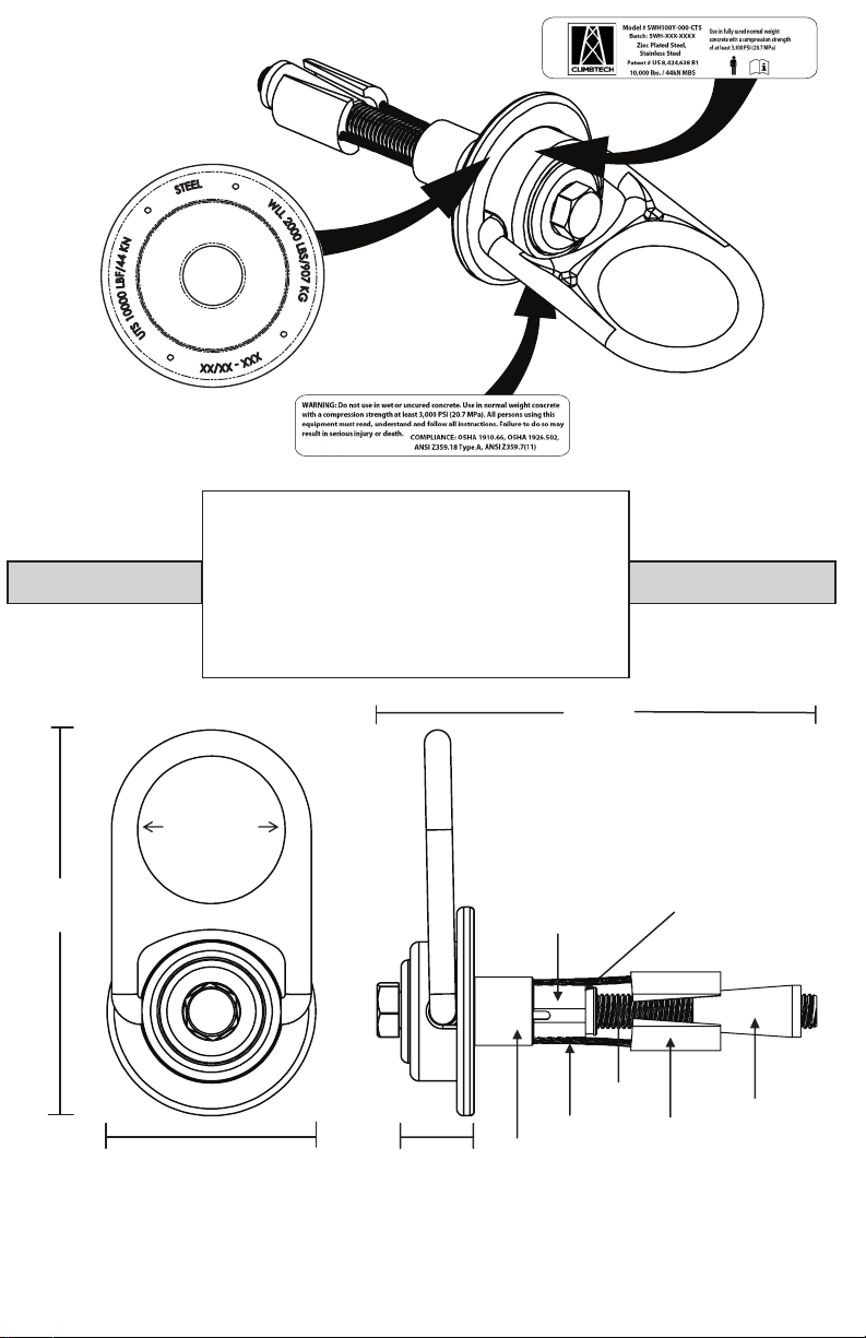
Minimum Breaking Strength (MBS):
10,000-lbf (44kN)
Maximum Capacity: See “Use Limitations”
Weight: 2.0-lbs (949g)
Regulatory Compliance
ANSI Z359.18 Type A, ANSI Z359.7-2011
OSHA 1910.66 , OSHA 1926.502
5.5”
(139.7mm)
2.25”ø
(57.15mm)
3”
(76.2mm)
6.25”
(15.88cm)
1”
(25.4mm)
Compression
Bushing
Retaining
Bushing
Cable
Bolt
Spoon
Cone
Sleeve
Compression Bushing: Polyethylene
Retaining Bushing: Zinc Plated Steel
Cone: Stainless Steel
Spoons: Stainless Steel
Bolt: Zinc Plated Steel
Sleeve: Zinc Plated Steel
Return Wire: Aircraft Cable
Swivel: Zinc Plated Steel
COMPONENT MATERIALS:
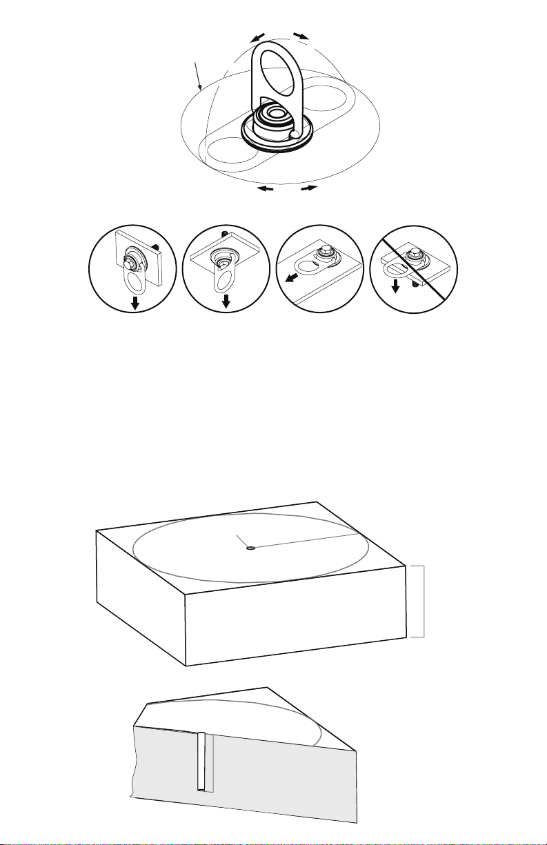
8.0”ø
(203.2mm)
180˚
360˚
ACCEPTABLE ACCEPTABLE IMPROPERACCEPTABLE
LOAD LOAD
LOAD
LOAD
5” min
depth
(12.7cm)
1”min
(2.54cm)
Section View:
10”
(25.4cm)
Drill 1ӯ
(2.54cm)
min from any edge
6”min
(15.24cm)
Hole to Edge:
DRILLING :
1. Use a hammer drill (SDS), drill a 1” (2.54 cm) diameter hole at least 5”
(12.7 cm) deep. The drilled hole must be straight and perpendicular to
the surface. Make sure the hole is of uniform diameter and free of peaks and
valleys on the inner wall. See diagram below.
2. Blow hole clean with compressed air.
3. Refer to the diagram below for hole location and requirements.
4. Always inspect the hole carefully when reusing a previously drilled hole.
LOADING CONDITIONS DIAGRAM
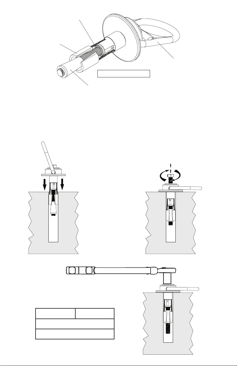
INSPECT BEFORE USE
Check for kinked
or frayed cables.
Look for signs
of wear on
spoons.
Check for deformation
of cone.
Swivel should
move freely.
INSTALLATION:
1. Before installing make sure cone is
below the spoons. Insert anchor into
hole so base plate rests at on concrete
surface.
2. Pull up on bolt while holding swivel
ush with the concrete. Tighten bolt by
turning it clockwise by hand until bolt is
fastened ush to swivel.
Drop In
Step 1. Step 2.
Pull Up
Bolt
Twist
Clockwise
LOAD: BOLT TORQUE:
85-ft-lbs
(9.60 Nm)
30-ft-lbs
(3.38 Nm)
10,000-lbf
(44 kN)
5,000-lbf
(22 kN)
3. Use a torque wrench to set pretension on
the bolt for the loading situation required for
application. Step 3.

TAP!!!
Step 1.
Step 2.
Step 3.
Unscrew min of
.75”(1.9cm)
.75”
(1.9cm)
REMOVAL:
1. Loosen bolt so that at least .75”
(1.9cm) of threads are exposed.
2. Use a hammer to tap down bolt and
disengage cone from spoons.
3. Pull anchor from hole.
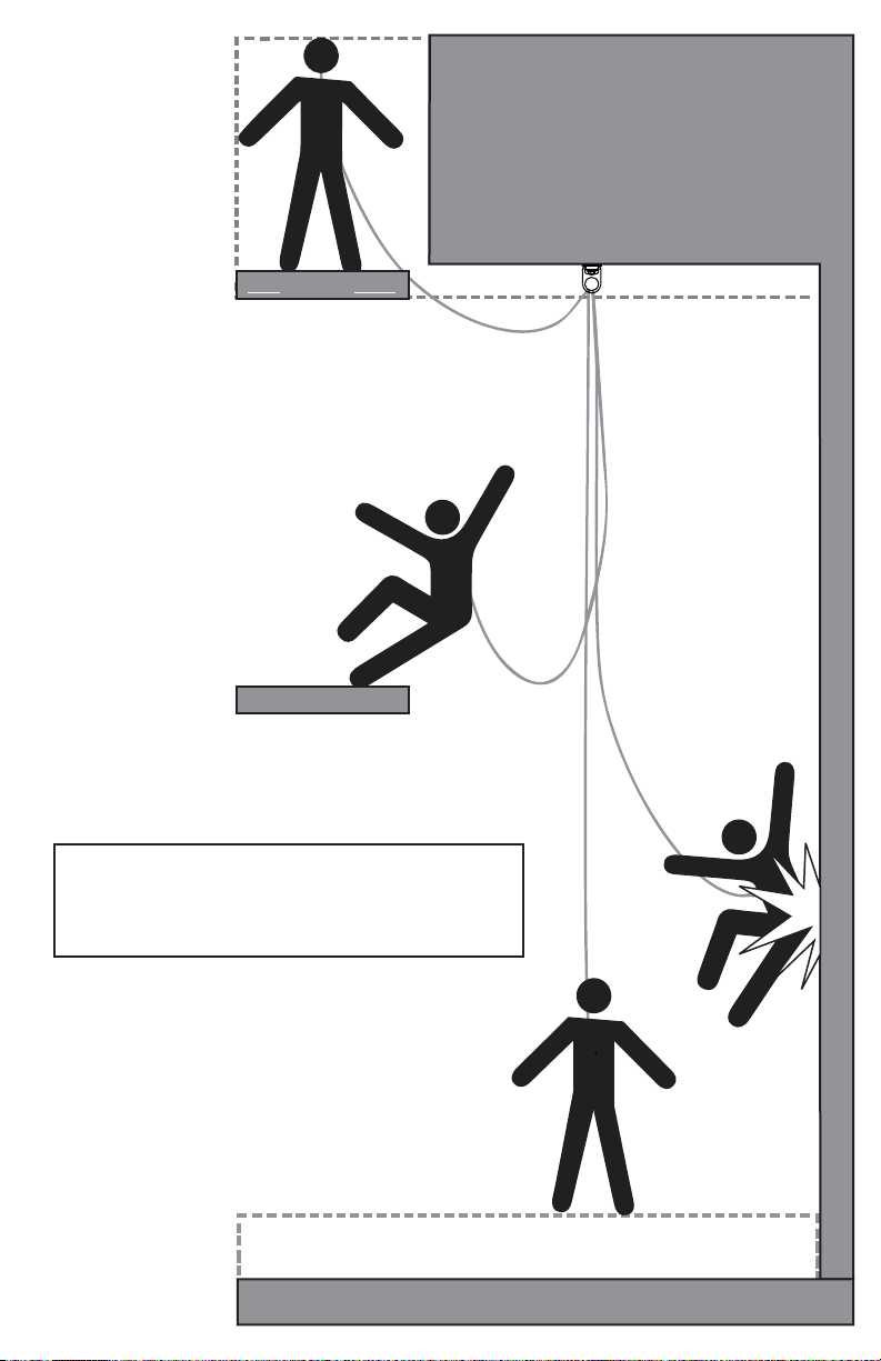
WORK SURFACE
WORK SURFACE
*All products subjected to fall arresting
forces should be removed from service
immediately!
(ANCHOR POINT)
*The structure the
anchorage is attached
to must be able to
support 10,000-lbf
(44kN) and installed
under the supervision
of a qualied person.
MINIMUM CLEARANCE 3ft (1m)
DECK/FLOOR/GROUND LEVEL
WARNING!!! SWING FALLS MAY OCCUR WHEN THE WORKER IS NOT DIRECTLY UNDER ANCHOR POINT.
*The user shall be equipped with a means of
limiting the maximum dynamic forces exerted
on the user during the arrest of a fall to a
maximum of 8 kN (1800-lbf).

Part Number Comments Inspector Name
Date
Inspection:
Ocial periodic inspection must be made at least annually. The inspection must be performed by a qualied
person other than the intended user. If severe weather or conditions exist then inspections must be carried
out more frequently. All inspection results must be logged in the space provided above.
1. Inspect swivel to make sure it is ush with mounting surface.
2. Make sure all labeling is axed to the unit.
3. Inspect anchoring system for signs of damage or wear to spoons or cone.
4. Make sure the unit can rotate 360° and D-ring can ip from side to side 180°.
5. When reusing a previously drilled hole, inspect for debris or wallowing.
6. Record inspection results in the space provide above.
*If any damage that could aect the strength or operation of the device, or unsafe condi-
tions are found, proper disposal is required. The anchorage connector must be rendered
unusable and then properly discarded.
MAINTENANCE, CLEANING AND STORAGE
Cleaning periodically will prolong the life and proper functioning of the product. The frequency
of cleaning should be determined by inspection and by severity of the environment. Clean with
compressed air and/or a sti brush using plain water or a mild soap and water solution. Do not use
any corrosive chemicals that could damage the product. Wipe all surfaces with a clean dry cloth
and hang to dry, or use compressed air. When not in use, store anchorage connectors in a cool, dry,
clean environment, out of direct sunlight and free of corrosive or other degrading elements.
INSPECTION AND MAINTENANCE LOG
Product Warranty, Limited Remedy and Limitation of Liability
WARRANTY: THE FOLLOWING IS MADE IN LIEU OF ALL WARRANTIES OR CONDITIONS, EXPRESS OR
IMPLIED, INCLUDING THE IMPLIED WARRANTIES OR CONDITIONS OF MERCHANTABILITY OR FITNESS
FOR A PARTICULAR PURPOSE. Equipment oered by ClimbTech is warranted against factory defects in
workmanship and materials for a period of one year from date of purchase or rst use by the original owner.
LIMITED REMEDY: Upon notice in writing, ClimbTech will repair or replace all defective items at ClimbTech’s
sole discretion. ClimbTech reserves the right to require that the defective item be returned to its plant for
inspection before determining the appropriate course action. Warranty does not cover equipment damage
resulting from wear, abuse, damage in transit, failure to maintain the product or other damage beyond the
control of ClimbTech. ClimbTech shall be the sole judge of product condition and warranty options. This
warranty applies only to original purchaser and is the only warranty applicable to this product. Please contact
ClimbTech technical service department for assistance.
LIMITATION OF LIABILITY: IN NO EVENT WILL CLIMBTECH BE LIABLE FOR ANY INDIRECT, INCIDENTAL,
SPECIAL OR CONSEQUENTIAL DAMAGES INCLUDING, BUT NOT LIMITED TO LOSS OF PROFITS, IN ANY
WAY RELATED TO THE PRODUCTS REGARDLESS OF THE LEGAL THEORY ASSERTED.
ClimbTech, LLC.
7303 Burleson Rd. Suite 901 Austin, TX 78744
1(512) 308-6440 / www.climbtech.com
Model Number:
Date of Manufacture:
Table of contents
Other ClimbTech Safety Equipment manuals

ClimbTech
ClimbTech BWA012N User manual

ClimbTech
ClimbTech FBAM47N User manual

ClimbTech
ClimbTech Freetech HARNESS-XXX-FRT User manual

ClimbTech
ClimbTech RAF075N User manual

ClimbTech
ClimbTech EAL12NC-72Y-C13 Guide

ClimbTech
ClimbTech RAF075N User manual

ClimbTech
ClimbTech SWY050N Guide

ClimbTech
ClimbTech BWA030N User manual

ClimbTech
ClimbTech SWY100N Guide

ClimbTech
ClimbTech SWS100N Guide


