Safety Warnings
lThis appliance should be installed by a competent and qualified electrician in
accordance to the IEE regulations.
lDO NOT operate the appliance with a damaged cord.
lDO NOT use this heater in dusty environments or where flammable vapours are
present(e.g. in a workshop or garage).
lDO NOTcover the heater. DO NOT allow the heater to come into contact with
flammable material for example curtains or furniture.
lDisconnect this heater before any repairs, cleaning or maintenance is carried out
upon it.
lThis heater should not be located directly below a power socket.
lDO NOT operate this appliance if the front cover is not correctly positioned on the
unit.
lDO NOT use this heater in the immediate surroundings of a bath, a shower or a
swimming pool.
lThis appliance is not intended for use by persons (including children) with reduced
physical, sensorary or mental capablities, or lack of experience and knowledge
unless they have been given supervision or instruction concerning use of the
appliance by a person responsible for their safety.
Children should be supervised to ensure that they do not play with the appliance.
lWARNING: the cable outlet must be controlled by a double pole switch with a
contact separation of at least 3mm in all poles. When located within a bathroom
the switch must be a pullcord; if located outside the bathroom it should be adjacent
to the entrance. The appliance must be located in a position that does not allow
any person to touch it whilst they are in the bath or shower.
Installation: THE APPLIANCE IS DESIGNED ONLY FOR WALL MOUNTING.
lChoose position carefully for mounting the appliance, enough space must be
left around appliance. NOTE: It is NOTpermissible to install this heater in Zones 1
or 2. Please install it outside Zone 2 in the undesignated area – see Figure 1
opposite.
lThe heater must be mounted at a high level –see opposite.
lLoosen the two screws at the top of the front of the heater and lift off the front
cover.
lDrill two 8mm holes on the wall at a distance of 190mm on a horizontal line,
another one at a distance of 115mm down from the horizontal line.
lInsert the three plastic plugs into the three holes, and then screw two of the screws
provided into the lower holes. Do not screw these two screws fully home as the
heater will hang on them later. As a guide they need to be left protruding by about
3mm
lHang the heater on the two screws. It may be necessary to mount and dismount
the heater a few times, slightly tightening and/or loosening the screws as required,
to ensure a snug fit.
M
Mi
in
ni
im
mu
um
mm
mo
ou
un
nt
ti
in
ng
gd
di
is
st
ta
an
nc
ce
es
s
A
A–
–2
28
80
0m
mm
mminimum of space required above the heater
B
B–
–2
25
50
0m
mm
mminimum space on either side of the heater
C
C–
–1
18
80
00
0m
mm
mminimum height from the floor
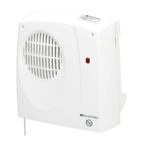
The HS2000X Downflow Heater provides an instant heat source for
kitchens and bathrooms and is styled to match our shower range.
lUse the wall bracket to secure the heater by fitting the last screw into the upper
hole.
lRemove the fixing board from inside the heater.
lThread the supply cable through the hole in the rear of the case.
lMake connections to the supply terminals according to the colour code (Please see
Electrical Connection). Ensure that there are no strands or whiskers protruding from
the terminals
lSecure the cable under the fixing board, ensure that the cable is griped firmly but
take care not to over tighten the screws.
lSelect the desired mode of operation using the switch i.e. I= 1kW fixed heat,
II=1kW fixed heat + 1kW variable thermostat controlled set the thermostat to the
mid position. Close and secure the front cover.
lRestore the power and switch on.
Adjustment
lThe adjustment of the interal thermostat must be carried out by a competent
person.
lSwitch off the main power and remove the fuse from the double pole
fused spur.
lRemove the two screws on the front of the case and remove the front cover.
lSelect the desired mode of operation using the switch i.e. I= 1kW fixed heat,
II=1kW fixed heat+ 1kW variable thermostat controlled
lTurn the thermostat control clockwise to increase the room temperature and anti-
clockwise to decrease.
lClose the front over and secure using the two screws, replace the fuse and switch
on the power supply.
Electrical Connection
Connect the electrical wires of this appliance to a fused spur according to the following
colour code – Blue: Neutral, Brown: Live – in accordance with NECEIC wiring
regulations, with a minimum cable size of 1mm2.
NB. If no fused spur is nearby consult a suitably qualified electrician.
RCD protected
sockets now
allowed beyond
3m from Zone 1
