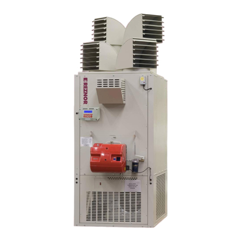
Nortek Reznor FSE Series Guide

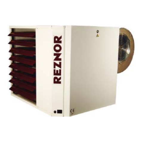
FLOOR STANDING WARM AIR HEATER
INSTALLATION/ COMMISSIONING/SERVICING
FSE Model Range (Gas & Oil)
Manual Part No. D301160 Issue H
®
Machinery Directive (2006/42/EC)
Low Voltage Directive (2014/35/EU)
Electromagnetic Compatibility Directive: (2014/30/EU)
Regulation (EU) 2016/2281
Gas Appliance Regulations (EU) 2016/426
Please read this document carefully before commencing installation, commissioning and/or servicing.
Leave it with the end user/site agent to be placed in their premises technical file after installation.
WARNING
Improper installation, adjustment, alteration, service or maintenance can cause property damage, injury or death.
All work must be carried out by appropriately qualified persons.
The manufacturer does not take any responsibility in the event of non-observance of the regulations concerning the connection of the apparatus
causing a dangerous operation possibly resulting in damage to the apparatus and/or environment in which the unit is installed.


Reznor, FSE, Installation Manual, EN 2020-02, D301160 Iss H
INDEX
General Health and Safety .....................................................................................................1
General .................................................................................................................................4
Compliance notices................................................................................................................5
Warranty ...............................................................................................................................6
Technical Data .......................................................................................................................8
Identification..........................................................................................................................8
Structure................................................................................................................................9
Pre installation .......................................................................................................................14
Handling................................................................................................................................15
Installation considerations......................................................................................................16
Safety area.............................................................................................................................17
Air supply and return .............................................................................................................17
Accessories ............................................................................................................................18
Flue gas discharge..................................................................................................................18
Combustion air......................................................................................................................19
Air intake and supply (ducted units only)................................................................................20
Burner position ......................................................................................................................21
Gas Installation/connection .................................................................................................... 21
Oil Installation/connection .....................................................................................................23
Storage tank..........................................................................................................................23
Pipe work and fittings............................................................................................................25
Burner technical details..........................................................................................................27
Electrical connections.............................................................................................................30
Control panel.........................................................................................................................32
Starting and stopping ............................................................................................................34
Inspections.............................................................................................................................35
Condensation check .............................................................................................................. 36
Indicators...............................................................................................................................36
Fan electric absorption...........................................................................................................36
Maintenance..........................................................................................................................37
Cleaning of gas or oil burner .................................................................................................37
Servicing................................................................................................................................39
Parts Lists. ............................................................................................................................. 40
ErP Data chart natural gas ...................................................................................................42
ErP Data chart propane gas ..................................................................................................43
ErP Data chart oil .................................................................................................................44
ErP Data chart kerosene .......................................................................................................45
CONTENTS

PAGE D Reznor, FSE, Installation Manual, EN 2020-02, D301160 Iss H
The FSE range of cabinet heaters combine innovative design with proven heat exchanger
technology to provide a high efficiency cost effective and durable range.
The units may be specified for either free blowing applications or for use with ductwork.
Model Range+
Gas fired cabinet heaters are suitable for use with Natural Gas (G20), most units can also be
specified for Propane (G31)
Oil fired cabinet heaters are suitable for use with Class D gas oil (35 sec), most units can also
be specified for Kerosene (28 sec oil). Oil fired cabinets are supplied complete with factory
fitted fire valve and oil filter
Vertical free standing models are available from 40kW to 300kW. Two stage burners are
fitted as standard along with a Smartcom Multi-zone control panel.
Options Inlet air filter
PRODUCT INTRODUCTION

Reznor, FSE, Installation Manual, EN 2020-02, D301160 Iss H
General Health and Safety
WARNING
Warning is used when failure
to heed or implement the
instruction(s) can lead to not
only component damage, but
also to a hazardous situation
being created where there is a
risk of personal injury.
CAUTION
Caution is used when failure
to follow or implement the
instruction(s) can lead to
premature failure or damage
to the heater or its component
parts
GAS LEAK EMERGENCY
If you can smell gas from or near the
heater:
• Do not try to light any appliance
• Do not smoke or light matches
• Do not turn electrical switches on or
off
• Open doors and windows, to air the
room
• Close the fuel control to the device
• if you still smell gas turn off the
the supply at the meter unless the
meter is in the cellar
• Raise the alarm and evacuate all
personnel to a safe place
• Promptly Call your Gas Emergency
number
Enter your gas emergency number below
• Do not store or use petrol or other
flammable vapours and liquids in the
vicinity of the appliance.
• In case of persisting problems, contact
your distributor
Improper installation, adjustment,
alteration, service, or maintenance can
cause property damage, injury, or death.
Read the installation, operation, and
maintenance instructions thoroughly before
installing or servicing this equipment.
Do not use this appliance if any part has
been immersed in water. Immediately call
a qualified service technician to inspect the
appliance and replace any gas control that
has been immersed in water.
Gas-fired appliances are not designed for
use in hazardous atmospheres containing
flammable vapours or combustible dust,
in atmospheres containing chlorinated
or halogenated hydrocarbons or in
applications with airborne silicone
substances.
Should overheating occur, or the gas supply
fail to shut off, shut off the manual gas
valve to the appliance before shutting off
the electrical supply.
This appliance is not intended for use by
persons (including children) with reduced
sensory or mental capabilities or lack of
experience and knowledge, unless they
have been given supervision or instruction
concerning use of the appliance by a
person responsible for their safety.
Children should be supervised to ensure
that they do not play with the appliance.
Carry out a risk assessment for the task to
be carried out and ensure the correct use of
any Personal Protective Equipment.
HEALTH AND SAFETY

PAGE 2 Reznor, FSE, Installation Manual, EN 2020-02, D301160 Iss H
Before using this appliance:
• Check that the voltage indicated on
the type plate corresponds to the mains
supply voltage.
• Ensure that the heater has been securely
fastened in its final mounting position
Location/Positioning
WARNING
The oil variant of the heaters must
be installed in accordance with
the current OFTEC regulations for
oil fired products.
Under no circumstances should
any item be placed on or above
any part of the heater, whether it
is being used or not.
All basic criteria must be satisfied
prior to commencing the
installation and commissioning
process.
The heater must be positioned
and installed to comply with all
relevant standards and guidelines.
And should also meet the local
and national fire regulations and
insurance criteria, this is critical
if the heater is to be installed
within a special risk area (e.g.
being; within close proximity to
where petrol engined vehicles are
stored or parked, where cellulose
spraying takes place, where
woodworking machinery is being
operated, etc,).
CAUTION
The heater must not be installed
within an area with unsuitable
conditions, e.g. where the
atmosphere is highly corrosive,
has a high degree of salinity, or
where high wind velocities may
affect burner operation.
Suitable protection should be provided
for the appliance when it is located in
a position where it may be susceptible
to external mechanical damage; for
example, fork lift trucks, overhead
cranes etc.
Indirect heaters must not be located in
hazardous areas, however, it is permissible
for the heater to supply air to such areas
The heater must not be installed within
an environment where there is a high
concentration of chlorides, fluorides, salts,
or other aggressive or volatile chemicals/
compounds. Nor should the heater be
positioned where the burner could be
adversely affected by high winds or
draughts.
The location chosen for the heater must
allow for the fitting of an effective flue
system.
The location must also allow for adequate
clearance for the air supply, return air
circulation, gas supply and electrical
supply, whilst also providing good and
safe working access. The heater must be
installed on a flat and level surface made
from non-combustible material, which is
sufficiently robust to withstand the weight
of the heater and any ancillary equipment.
General requirements
WARNING
Unauthorised modifications to the
appliance, or departure from the
manufacturers guidance on
intended use, on recommended
practices may constitute a hazard.
To ignore the warning and caution
notices, and advice from the
manufacturer on installation,
commissioning, servicing, or use,
will jeopardise any applicable
warranty.

Reznor, FSE, Installation Manual, EN 2020-02, D301160 Iss H
Moreover, such a situation could also
compromise the safe and efficient
running of the appliance itself, and
thereby constitute a hazard
All heaters must be earthed.
The installation of the appliance must meet
all the relevant European, national, and
local criteria
Prior to installation the following
points should be considered;
• The position of the heater for the
optimum efficient distribution and
circulation of warm air.
• The position of the heater relative to the
route of the flue
• The position of the heater relative to the
supply of fuel
• The position of the heater relative to the
electrical services, and if appropriate,
any additional controls.
• The position of the heater relative to the
supply of fresh air
• The height if applicable at which the
heater is to be mounted and potential
stratification /circulation problems.
• The position of the heater relative to
service and maintenance requirements
Electrical supply
CAUTION
Ensure the supply is in accordance
with the manufacturer’s
recommendations and is as stated
on the appliance data plate.
The main electrical supply must not
be switched off or disconnected as a
method for stopping the heater, the
exception to this is in an emergency,
or during servicing, where the heat
exchanger has been given sufficient
cooling time to prevent damage from
occurring. Claims for damage will not
be considered if they resulted from
incorrect wiring or incorrect use of the
heater
Wiring external to the heater must be
installed in accordance with any local,
national, and European regulations.
The means of connection to the main
electrical supply must allow for complete
electrical isolation of the heater,
furthermore, in the case of a unit wired for
a three phase supply, the supply should
only be used to serve the heater itself and
no other plant or equipment.
The position of the isolation switch must
be such that it is adjacent to the heater and
easily accessible at all times. In addition,
the isolator itself must have a contact
separation of not less than 3mm.
The Control fuse ratings are detailed on the
appliance data plate.
WARNING
Ensure that the electric and gas
supplies are turned off before any
electrical work is carried out on
the heater.
Ensure that wiring cannot make contact
with any surfaces liable to be subject to
high temperatures or where the insulation
of the wiring could be impaired as a result
of such contact

PAGE 4 Reznor, FSE, Installation Manual, EN 2020-02, D301160 Iss H
General
This manual is an integral part of the
heater, therefore it should always be
carefully kept and it should always be
provided together with the heater, if it is
transferred to another owner or user. If
this manual is damaged or lost, a new one
should be requested from the installer or
from the manufacturer. After unpacking
the product, please check the contents to
ensure all components are present. If not,
please contact your supplier.
The installation must be carried out by
suitably qualified personnel who, at the end
of the work, will commission the appliance
and issue to the owner a copy of the
commissioning report, which also confirms
that the installation has been carried out in
accordance with regulations & standards
applicable to the country of use and
in accordance with the manufacturers
instructions.
This appliance has been manufactured
specifically for room heating and must be
used for this purpose. Contractual liability
of the manufacturer in respect of damages
caused to people, animal or premises by
incorrect installation, settings, maintenance
or by improper use of the heater is
excluded.
During the initial start-up, there may be
the formation of odours and fumes due
to the evaporation of the oil added to
protect the heat exchanger during storage;
this is normal and will disappear after a
short period. It is recommended to ensure
suitably ventilation for room.
WARNING
If the appliance is to remain
unused for long periods, it is
recommended that the following
operations are carried out:
• Turn the appliances’ electrical supply off
via the local isolator.
• Close the main fuel supply valve
If there is a long period of time between
operation, it is recommended that you
contact your installer to carry out the new
start-up.
The heater shall be fitted with approved
accessories only. The manufacturer is
not liable for damages arising from the
improper use of the heater or from the use
of non-original materials or accessories.
References to Laws, Regulations, Directives
and Technical Rules mentioned in this
manual are provided only for information
purposes and are in force when the manual
is printed.
The introduction of new provisions
or amendments to current laws does
not represent an obligation of the
manufacturer towards third parties. Repairs
or maintenance are to be performed by
trained personnel only.
Do not modify or tamper with the
appliance, the manufacturer will not
be held responsible for any third party
modifications to the heater.
The services that are to be connected (fuel
pipes, power supply, etc.) must be suitably
secured and must not be hazardous with
the risk of tripping.
The manufacturer is responsible for the
product compliance with Laws, Directives
or Construction Rules in force when the
product is marketed. The knowledge and
observance of the laws and standards
regarding plant design, installation,
operation and maintenance are the sole
responsibility of the designer, installer and
user. The manufacturer shall not be held
responsible for failure to comply with
the instructions of this manual, for the
GENERAL

Reznor, FSE, Installation Manual, EN 2020-02, D301160 Iss H
consequences of any operations carried
out and not specifically provided for or for
translations open to misinterpretation.
The electrical system must feature suitable
individual and independent electrical
protection for each appliance which, in
case of accidental failure, will be activated
on the single appliance without prejudice
to the proper operation of the other units
present on the installation.
Note:
The appliance is designed to be operated
with the heating capacity and the air flow
rate specified in the Data Sheet. If the
heating capacity is too low and/or the air
flow rate is too high, combustion products
may condensate, resulting in the irreparable
corrosion of the heat exchanger. If the
heating capacity is too high and/ or the air
flow rate is too low, overheating of the
heat exchanger may occur, resulting in the
activation of the high temperature safety
devices and could cause damage to the
exchanger
Disposal instructions
Disposing of the appliance must be done by
an authorised company and in compliance
with the applicable laws. Before taking
waste to Authorised Collection Centres,
dismantle and separate the various
materials that compose it which in
summary are:
• Ferrous materials
• Aluminium and copper
• Electrical wiring
• Seals and insulating materials
• Plastic materials
• Electronic cards
Compliance notices
• The heater range detailed herewith
are manufactured within a strictly
controlled quality environment within
the parameters of ISO 9001.
These instructions are only valid if the
following country code is on the appliance
GB. IE. If this code is not present on the
appliance, it is necessary to refer to the
technical instructions which will provide
the necessary information concerning
the modification of the appliance to the
conditions of use for the country.
The manufacturer has taken reasonable and
practical steps to ensure that all heaters are
safe and without risk when properly used.
These heaters should therefore only be used
in the manner and purpose for which they
were intended, and in accordance with the
recommendations detailed herewith. The
manufacturer supports all new products
being supplied to their customers with
a comprehensive information pack; this
clearly defines mandatory instructions for
the safe installation, use, and maintenance,
of the appliance(s).
Where proprietary items are incorporated
into any of the heaters, detailed
information and instructions are also
provided as part of the information pack. It
is the responsibility of the installer, owner,
user, or hirer of the heater to ensure that
they are familiar with the appropriate
information/manuals supplied by the
manufacturer and the safety instructions. In
addition, operators must be suitably trained
in the use of the appliance so as to ensure
its continued safe and efficient use.
The manufacturer has a commitment to
continuous improvement and therefore
reserve the right to amend or change the
specification of Warm Air Heater subject to
compliance with the appropriate European,
national and local regulations

PAGE 6 Reznor, FSE, Installation Manual, EN 2020-02, D301160 Iss H
The Warm Air Heater range
conforms to the following
standards:
EN 292-1
Safety of Machinery - Basic Concepts,
General Principles for Design Basic
Terminology Methodology
EN 292-2
Safety of Machinery - Basic Concepts,
General Principles for Design Technical
Principles and Specifications
EN 60204-1
Safety of Machinery - Electrical Equipment
for Machines Specification for General
Requirements
EN 60335-1
Safety of Household and Similar Electrical
Appliances General Requirements
EN 50165
Electrical Equipment of non-electric heating
appliances for household and similar
purposes, safety requirements
EN 55014
Limits and methods of measurement of
radio disturbance characteristics of electrical
motor-operated and thermal appliances for
household and similar purposes, electrical
tools and similar electric apparatus
EN 1020
Non-domestic forced convection gas-fired
air heaters. Machinery Directive (2006/42/
EC) Low Voltage Directive (2014/35/EU)
Electromagnetic Compatibility Directive:
(2014/30/EU) Regulation (EU) 2016/2281
Gas Appliance Regulations (EU) 2016/426
Warranty
The heater is supplied with a 1 year parts
and labour warranty and a further year on
all parts excluding consumables.
The warranty commences from the date
of dispatch from the manufacturer, and
is subject to the terms detailed within the
Manufactures ‘conditions of business’.
Note: The warranty may be invalidated
if:
• The installation is not in accordance
with the general requirements of this
manual.
• The flue arrangement and air supply for
the heater are not in accordance with
the manufacturers recommendations,
codes of practice, or similar standards.
• Air flow through the heater is not in
accordance with the manufacturers
technical specifications.
• Internal wiring on the heater has been
tampered with or unauthorised service
or repairs undertaken.
• The main electrical supply input to the
heater has been interrupted during the
heating mode.
• The heater has been subject to and
affected by the ingress of water in any
form.
• The heater is not operated at the
rating(s) laid down in the manufacturers
technical specifications.
• The heater has not been operated or
used within the normal scope of its
intended application.
• The manufacturer’s recommended
minimum service requirements have not
been complied with.

Reznor, FSE, Installation Manual, EN 2020-02, D301160 Iss H
Note: All warranty claims must contain
the following info to enable processing
to take place.
• Heater model
• Heater serial number
• Order reference/date of order, together
with
• Full installation details (name and
address Details or symptoms of fault
• Installers name and address
• Commissioning and service records
Faulty parts must be returned to the
supplier, the address of which is provided
at the rear of this manual. Any such parts
will undergo inspection to verify the claim.
Replacement parts supplied prior to this
may be charged, and a credit supplied upon
subsequent validation of the warranty
claim. Consumable items are specifically not
included within the scope of the warranty.
Note: Notification is required the
immediate moment a fault is suspected.
The manufacturer will not accept
responsibility for any additional damage
that has been caused, expense incurred, or
consequential loss resulting from any failure
of the heater(s).
WARNING
Nortek Global HVAC equipment
must be installed and maintained
in accordance with the
requirements of the Codes of
Practice or rules in force.
All external wiring must comply
with the codes of practice or
rules in force in the country of
installation.
Improper installation, adjustment,
alteration, service or maintenance
can cause property damage, injury
or death.

PAGE 8 Reznor, FSE, Installation Manual, EN 2020-02, D301160 Iss H
Technical Data
Heat Exchanger
Manufactured from welded stainless steel,
it can be easily inspected for cleaning and
maintenance operations and comprises the
following elements:
• Cylindrical shaped combustion chamber
in stainless steel with low thermal load.
• Heat exchanger elements in steel with
large surface area containing staggered
and opposing indentations.
External casing
The external casing consists of panels in a
pre-painted and/or powder-coated sheet
metal, also includes:
• Frame structure in press-folded profile
with aluminium die-cast corner joints.
• Sandwich panels with internal glass
wool insulation.
Fan assembly
Consists of one or more centrifugal fans
with a low level of sound emission and high
performance.
• Three-phase models are driven by
electric motors with a pulley and belt
transmission system.
• Single-phase models use a direct drive
fan.
Safety and control thermostat
The appliances are equipped with
thermostats with the sensor located on the
air supply (pre-calibrated and electrically
connected in the factory), with the
following functions:
• “FAN” function (FAN thermostat –
calibration: +25/+35°C). Activates the
fans max. 60 seconds after the burner
has started and stops them approx. 4
minutes after the burner has switched
off.
• “SAFETY” function (TR safety
thermostat - factory calibration + 80°C),
has the function of interrupting the
burner operation in case of abnormal
overheating of the air. It is automatically
reset. It shall be correctly calibrated
when it is used for the first time.
• “LIMIT” function (LM Thermostat
- sealed calibration: +100°C): will
stop the burner if the air becomes
overheated abnormally. Reset is manual.
Flue pipe
The heater is fitted with a circular flue collar
to enable a condense TEE to be inserted
safely and fixed at the start of the flue
system.
Identification
The warm air heaters can be
identified through:
• The data plate, applied on the heater,
that specifies the main technical
performance data.
• In the event of damage or loss, request
a duplicate from the manufacturer.
Receiving the product
The appliance is supplied with:
• Document envelope including:
• User guide
• Wiring diagram
• Labels with bar code
• Riello burner for installer fitting
• Burner Owner’s Manual
TECHNICAL DATA

Reznor, FSE, Installation Manual, EN 2020-02, D301160 Iss H
Fixed protection
In order to avoid accidental contact with
the movable parts of the machine, check if
the following fixed protections have been
properly installed:
• Grille on air intake.
• Appliance infill panels.
• Burner casing.
Structure
Legend
1. Secondary heat exchangers
2. Combustion chamber
3. Rear flue manifold
4. Front flue manifold
5. Heat exchanger inspection door
6. Flue connection
7. Burner mounting
8. Flame spy hole
9. Fan
10. Fan motor
11. Electrical panel
12. Fan-limit tri-thermostat
13. Smartcom controller
Figure 1. Component layout
Figure 1 cont. Component layout
Figure 2. Heat exchangers models
60–300
Figure 3. Heat exchanger model 40

PAGE 10 Reznor, FSE, Installation Manual, EN 2020-02, D301160 Iss H
Figure 4. Dimensions and weight
MODEL A B C Net weight Flue Ø mm Flue Ø nom
FSE 40 600 770 1500 145 130 5”
FSE 60 650 950 1650 225 150 6”
FSE 75 650 950 1650 245 150 6”
FSE 100 800 1200 1900 310 180 7”
FSE 145 800 1200 1900 345 180 7”
FSE 175 1000 1500 2150 485 205 8”
FSE 225 1000 1500 2150 525 205 8”
FSE 300 1250 1800 2360 660 305 12”
Table 1 – Without burner

Reznor, FSE, Installation Manual, EN 2020-02, D301160 Iss H
Gas Model FSE
40
FSE
60
FSE
75
FSE
100
FSE
145
FSE
175
FSE
225
FSE
300
Flue type Class B23 / B53
Heat output (G20) kW 39.0 56.8 68.5 99.2 143.5 175.9 223.4 300.0
Heat input nett (G20) kW 43.0 63.0 75.2 110.0 158.0 195.0 248.0 328.0
Efficiency nett % 91 91 91 91 91 91 91 92
Gross flue gas temperature (1) °C 210 220 205 215 210 215 220 200
Heat output low fire kW 28.0 38.2 52.9 67.1 99.9 124.0 153.6 230.6
Heat input nett low fire kW 30.0 41.0 56.7 72.0 106.0 131.2 165.0 244.0
Efficiency low nett % 94 93 94 93 95 95 93 94
Gross flue gas temperature (1) °C 155 155 155 155 140 140 155 140
Nominal inlet pressure G20
natural gas mbar 20
Natural gas G20 consumption m³/h 4.6 6.7 8.0 11.6 16.7 20.6 26.2 34.7
Nominal inlet pressure G31
LPG gas mbar 37
Nominal inlet pressure G31
(NL) LPG gas mbar 30
LPG gas G31 consumption litres 6.8 9.8 11.3 17.2 24.4 30.9 39.2 50.2
Heating Oil Model FSE
40
FSE
60
FSE
75
FSE
100
FSE
145
FSE
175
FSE
225
FSE
300
Flue type Class B23 / B53
Heat output (35 sec) kW 40.0 55.5 69.9 96.4 144.9 175.1 218.9 304.3
Heat input nett (35 sec) kW 43.0 60.0 75.2 106.0 158.0 189.3 235.0 328.0
Efficiency nett % 93 92 93 91 92 92 93 93
Gross flue gas temperature (1) °C 195 200 195 240 230 205 190 200
Heat output low fire kW 33.2 44.4 53.5 84.3 113.8 133.3 158.6 222.5
Heat input nett low fire kW 35.0 48.0 56.7 90.6 120.9 141.1 165.0 235.0
Efficiency low nett % 95 93 94 93 94 94 96 94
Gross flue gas temperature (1) °C 150 170 165 200 170 165 120 150
Heating oil (35 sec)
consumption kg/h 3.6 5.0 6.3 8.9 13.3 16.0 19.8 27.6

PAGE 12 Reznor, FSE, Installation Manual, EN 2020-02, D301160 Iss H
Kerosene Model FSE
40
FSE
60
FSE
75
FSE
100
FSE
145
FSE
175
FSE
225
FSE
300
Flue type Class B23 / B53
Heat output (28 sec) kW 40.0 57.3 69.8 102.1 138.4 182.0 210.4 305.4
Heat input nett (28 sec) kW 43.0 61.0 75.2 110.0 150.0 195.0 225.0 328.0
Efficiency nett % 93 94 93 93 92 93 93 93
Gross flue gas temperature (1) °C 180 170 190 205 210 185 200 195
Heat output low fire kW 35.8 45.3 62.8 88.5 124.4 153.0 129.2 251.2
Heat input nett low fire kW 38.0 48.0 67.0 95.0 134.0 161.0 135.0 265.0
Efficiency low nett % 95 95 94 94 93 96 96 95
Gross flue gas temperature (1) °C 155 155 170 185 195 145 145 155
Kerosene (28 sec) consumption kg/h 3.6 4.8 6.2 8.9 12.4 16.0 18.7 26.1
Model FSE
40
FSE
60
FSE
75
FSE
100
FSE
145
FSE
175
FSE
225
FSE
300
Fan thermostat calibration °C +35
Limit thermostat calibration °C +100
Range of use °C -15/+40
External static pressure Pa 80 150 150 150 150 150 150 150
Supply air fan quantity No. 1
Fan size Type 10-10 280 280 355 355 355 355 400
Sound level (2) dB(A) 74.0 76.9 81.6 79.8 85.5 76.6 82.7 82.9
Nominal temperature rise °C 33 35 33 35 39 37 35 36
Nominal airflow rate m³/h 3500 4800 6300 8300 10900 14000 19000 25000
Nozzle quantity (nozzle version
only) No.22333444
Combustion chamber pressure mbar 0.2 1.1 1.2 1.4 2.0 1.4 1.5 2.9
(1) Referred to combustion air temperature +15°C
(2) Sound power at inlet of fan
Table 2 – Technical specifications

Reznor, FSE, Installation Manual, EN 2020-02, D301160 Iss H
Model FSE 40 FSE 60 FSE 75 FSE 100 FSE 145 FSE 175 FSE 225 FSE 300
CLASS 4
Table 3 – NOx emissions class table (UNI
EN 1020 reference):
Country Category Country Category
AL II2H3B/P, II2H3P IE II2H3P
AT II2H3B/P ET II2H3+
BE I2E(R)B, I3P LT II2H3B/P, ll2H3P
BG II2H3B/P, II2H3P LU II2E3B/P
CH II2H3B/P LV I2H
CY I3B/P, I3P MC II2H3B/P, ll2H3P
CZ II2H3B/P, ll2H3+, ll2H3P MT I3B/P, I3P
DE II2ELL3B/P NL II2L3P
DK II2H3B/P NO I3P
EE II2H3B/P PL II2E3PB/P
ES II2H3+ PT PT II2H3+
FI II2H3B/P RO RO II2H3B/P, II2H3P
FR II2ER3P SE II2H3B/P
GB II2H3P YES II2H3B/P, ll2H3P
GR II2H3B/P SK II2H3B/P, ll2H3+, ll2H3P
HR II2H3B/P, ll2H3P TR II2H3B/P
HU II2H3B/P
Table 4 – Gas categories table –
Destination country
Class 4, for values that are not greater than
100 mg/kWh
Gas categories and emissions class
Always ensure that the gas burner is certified for the correct category. The unit is certified in
EU countries and countries to soon enter the EU, according to the gas categories shown

PAGE 14 Reznor, FSE, Installation Manual, EN 2020-02, D301160 Iss H
Pre installation
Packaging
The heater will usually be supplied wrapped
in heavy gauge polythene, non assembled
parts will be supplied separately.
Prior to installation, the assembly of the
heater should be completed, it is advisable
that this is undertaken in the area where
the heater is scheduled to be sited.
CAUTION
It is strongly advised that when
positioning the heater the lifting
eyes are used, thereby reducing
the risk of inadvertent damage
being occasioned to the heater.
Flooring
The heater must be installed on a level non-
combustible surface capable of supporting
the weight of the heater and any ancillary
equipment.
Electrical Installation/connection
Cabinet heaters are available either for
415V 50Hz 3PH or 230V 50Hz 1PH supplies
depending upon the model specified.
The electrical supply must be as specified
and suitable for the heater, and must be
run within conduit to a point adjacent to
the heater, and be terminated to provide an
isolation point that will prevent remote or
inadvertent activation.
Cables, conduit, and fittings that are used
to make the connection between the
isolator and the heater must conform to the
appropriate local and national regulations.
All heaters are supplied fused and pre-
wired, all must be earthed.
Final connections for any additional
external controls must be completed on
site, and must be carried out according to
local and national regulations. Separate
user information is provided for the time
control unit and the burner, and forms
part of the product information pack
which accompanies every heater when
despatched.
WARNING
Always isolate from the mains
electrical supply before
commencing work on the heater.
Always ensure that the appropriate
personal protective equipment is used.
Air Distribution Installation
The materials selected must be of low heat
capacity, and it is preferable that all warm
air ductwork is thermally insulated
.
Where ducting may be subject to
deterioration from exposure to moisture
or high humidity material selection and
insulation are prime considerations. Joints
and seams must be airtight and fastened
securely and designed to remain so, even
when operating at high temperatures.
Adequate support must be designed into
the layout of the ductwork to ensure that
the integrity of the seams and joints is
maintained.
The support must be independent and
separate from the heater and the ducting,
to allow for free movement during
expansion and contraction.
Where ducting passes through walls or
partitions sufficient clearance must be left,
irrespective of any fire stop requirement, to
allow for expansion and contraction.
INSTALLATION

Reznor, FSE, Installation Manual, EN 2020-02, D301160 Iss H
Failure to adhere to these latter two
points can result in the generation and
transmission of excess noise.
Where ducting is installed in concrete
flooring a permanent membrane must
be used to isolate the ducting from the
corrosive effect of the alkaline salts within
the concrete.
Care should be taken to ensure that soft
insulation material does not become
compressed and thereby lose its insulation
effectiveness.
The following sub-assembly parts should be
assembled to allow installation to continue.
Vertical Nozzle Models
For free blowing applications it will be
necessary to complete the final assembly
before continuing with the installation.
The nozzles should be pushed home on
the spigots and positioned to provide
the desired airflow. When in the correct
position fix in place with drill screws.
• Ensure louvres are adjusted outwards
and ensure blades are not resonating.
• The nozzles should be securely fixed in
their desired position on completion of
commissioning.
CAUTION
Care should be taken when
adjusting the louvre blades on the
outlet nozzles, closing too many
blades could lead to the heater
tripping on high limit. Should this
occur please reset the limit device
and gradually open nozzles until
the heater no longer trips.
Please note that fully closing the
louvres on the nozzle above the
limit device should be avoided at
all times.
Figure 5 Nozzle system
Handling
Handling must only be done by a qualified
engineer. If a fork-lift is used, pitchfork
the machine in the lower part using the
appropriate ways in the wood pallet.
Shipping and handling must be carried out
with extreme care to avoid damage to the
unit and danger to the persons involved.
During transportation and handling, it is
forbidden to stand near the unit. Use the
forklift forks with a minimum length equal
to the width of the machine.
If belts or ropes are used, a rocker arm
must be used (not included) to prevent
the pressure exerted by the same from
damaging the structure of the unit. Should
it be necessary to place more than one unit
on top of each other, observe the index
indicated on the packaging itself and be
very careful when aligning the packages
so as not to create unstable stacks. If
the device needs to be moved by hand,
make sure that there is enough workforce
available in proportion with the weight
indicated in Figure 6 “dimensions and
weight” and depending on the distance to
cover.
We recommend the use of personal
protective equipment (PPEs).

PAGE 16 Reznor, FSE, Installation Manual, EN 2020-02, D301160 Iss H
Figure 6 Handling
Installation considerations
The installation location must be
determined by the system designer and/
or by a competent person able to take
into account technical requirements, the
standards and regulations in force.
Generally, special permissions need to be
obtained. (E.g.: regulations con concerning
zoning, architecture, fires, environmental
pollution, noise emission, etc.).
It is important all users have full permission
before the installation can begin.
To properly install the heater,
bear in mind that the heaters
should:
• Be placed on a flat surface, capable of
bearing its weight;
• Be supported over the entire perimeter
of the lower base;
• Be placed on a surface whose deflection
and strength is such that it can prevent
vibrations from reaching underneath;
• Respect the clearance distances in
order to allow for a correct flow of air
and normal cleaning and maintenance
operations;
• Maintain the safety distances from
flammable material;
• Be placed close to a flue chimney;
• Be able to be connected to the fuel
source
• Be close to an electrical socket;
• Allow for easy maintenance and
inspections;
• Be fitted with the ventilation openings
required by the relevant regulations.
It is forbidden to install it:
• In places where there are aggressive
atmospheres;
• In tight spaces where the sound level
of the heater can be increased by
reflections or echoes;
• In corners where leaves could
accumulate or where other objects
could clog the air passage and reduce
the heater efficiency;
• In pressurised places;
• In de-pressurised places;
• Outdoors, if not provided with
protection against bad weather
conditions.
This manual suits for next models
8
Table of contents
Other Nortek Heater manuals

Nortek
Nortek Ambirad Vision VSX Installation guide

Nortek
Nortek REZNOR GUARDIAN GB Series User manual

Nortek
Nortek C84DA Series User manual

Nortek
Nortek RENZOR GUARDIAN GB User manual

Nortek
Nortek H9HK Series User manual

Nortek
Nortek C8QV Series User manual

Nortek
Nortek Reznor RHC DJL 8000 Guide

Nortek
Nortek Reznor 85 User manual

Nortek
Nortek AIRBLOC ACM900SE6 User manual

Nortek
Nortek C6B-T User manual