Nidec-Shimpo TTC Series User manual

The TTC Digital Torque Tool Tester is a simple operation test in-
strument for quickly checking torque tool performance up to 590
ft-lb (800 N-m). The TTC Series provides exceptional accuracy for
measuring torque on various products including torque wrench-
es, manual screwdrivers, electric screwdrivers, pneumatic screw-
drivers and other torque controlled power tools.
The TTC’s provide long operation life and power flexibility with the
ability to work from the internal rechargeable battery or included
AC adapter. The TTC’s have six modes of operation: Track for live
readings, Peak which records the highest level over a test, First
Peak which records a reading after a programmed decrease, Auto
Peak which resets after a period of time, Auto First Peak which
resets the first peak after a period of time, Double Peak which
provides two separate peak readings from programmed decreas-
es. Preset operation with programmable tolerance thresholds for
quick pass fail tool test is available in all modes.
The analog bar graph on the backlit, reversible LCD aids users
by providing the resultant torque’s current position compared to
the full scale range along with the direction of the force. Pass/fail
icons produce live test feedback allowing instant determination of
the results.
Every tester comes standard with USB and RS-232 outputs. The
TTC’s software enables the uploading of data and the additional
statistical analysis with its auto-calculation of the selected values.
These excellent features make the TTC Torque Tool Testers a valu-
able and versatile addition to the production and quality control
departments.
TTC Series Torque Tool Tester
Operation Manual
Operators should wear protection such as a mask and gloves in case
pieces or components break away from the unit under test.
Whether the unit is ON or OFF, DO NOT exceed the capacity of the
sensor. NEVER exceed 120% of the rated capacity, or the torque sensor
will be damaged. At 110% of the rated capacity the display will flash
a warning.
Measure in line torque only. DO NOT attempt to measure forces at an
angle to the sensor – damage to sensor may result.
Do not attempt to repair or alter this instrument. Warranty will be voided
and damage to the unit may result.
Use and store within the stated temperature and humidity ranges, or
damage and failure may result.
Ensure during testing unit is properly mounted & secured to stable sur-
face. Mount display with the two integral 8.5 mm mounting holes only.
External sensor models use all four integral mounting holes.
If not using this instrument for extended periods of time, remove the
batteries to prevent potential battery leakage from causing product
damage.
SPECIFICATIONS
Measuring Range: 0.5% - 100% capacity
Accuracy: ± 0.3% of reading
Units of Measure:N-cm, N-m, in-lb, ft-lb, kg-cm (depending on
range)
Measure Modes: Track, Peak, First Peak, Auto Peak, Auto First
Peak, Double Peak & Preset
Tool Socket Size: TTC-2/5/10: 1/4” & 1/2” (6.3 & 12.5 mm);
TTC-20/50/100/200: 3/8” & 1/2” (10 & 12.5 mm); TTC-500/800: 3/4”
(19 mm)
Overload Protection: 120% of Full Scale
Sampling Rate: 2000 Hz
Peak Capture Rate: 0.05 s
Display: 160* 128 Dot matrix backlit LCD
Display Update Rate: 10 times/sec
Resolution: See Chart
Memory: 1000 data
Set Point: Programmable High and Low Limits
Battery Indication: Battery icon flashes when low
Charger/Adapter: Universal USB charger, input 100 - 240 V ac
50/60 Hz
Operating Temperature: 14 to 104ºF (-10 to 40ºC)
Humidity Limit: 20 - 80% RH
Power: 3.6 V dc 1600 mAH Ni-MH
Battery Life: Approx. 16 Hours continuous on full charge
Output: USB, serial port RS-232, High and low limit NPN
Dimensions: Display TTC-I: 7.75 x 7 x 3.3” (197 x 180 x 83 mm);
Display TTC-E: 7.75 x 7 x 3” (197 x 180 x 75 mm);
External Sensor (50, 100 N-m): 4.3 x 3.3”(110 x 83 mm);
External Sensor (200, 500 & 800 N-m): 4 x 3.8” (100 x 98 mm)
Product Weight: TTC-I: 3.3 lb (1.5 kg); TTC-E Display: 2.6 lb (1.2
kg); TTC-E-200/500/800 External Sensor: 4.4 lb (2 kg)
Package Weight: TTC-I: 6.5 lb (3 kg); TTC-E-200/500/800: 10.2
lb (4.6 kg)
Warranty: 1 year
Certification: CE
Included Accessories: USB cable, charger adapter, cal. cert.
printer cable, square driver adapter connector
Optional Accessories: RS-232 cable, Rundown adapters,
Printer. Note: Software available for free at www.shimpoinst.com
1.800.561.8187
-Direct.ca

1. LCD SCREEN STANDARD VIEW
Test Mode Icons:
2. Battery Icon: Battery level or charging status. Flashes when
gauge needs to be recharged.
3. OK/OV Preset Indicator:
4. Torque Icons: Indicates force direction.
5. Current measured value
6. Analog Bar: Indicates current position within full scale. When
the bar enters the area enclosed by the dotted line, this
signifies the full scale capacity is exceeded by an overload
condition.
7. Storage Icon: Indicates data is being saved.
8. System time
9. Units Indicator: Selected engineering unit.
10. Statistics X: Average; R: Variance
11. Data list: Five Point Measurement in Peak & First Peak Modes
12. Key Setting Mode: Printer Icon Key press will print. Disc icon
key will store reading.
13. Double Peak Mode Percentages
14. Sensor Icons: TTC-E Only
2
Under Lower Limit
Between Low Limit & Upper Limit
Over Upper Limit
Clockwise (CW)
Counterclockwise (CCW)
Track: Real Time, live measuring mode
Peak: Reading will not change until a higher value is mea-
sured
First Peak: Captures First Peak after a decrease has been
detected. Drop Ratio set in menus.
Auto Peak: Resets Peak after a programmed time period
Auto First Peak: Resets the First Peak after a programmed
time period. First Peak drop Ratio set in menus
Double Peak: Captures two First Peak values. Both drop
ratios set in drop ratio menu
Digital View
Graphic View
135
9
2
8
7
10
6
4
Preset: Set the upper & lower limit for GO/NG testing
1
2
4
6
7
11
2. MODE DIAGRAM DETAILS
12
12
10% 20%
14
Sensor is Connected
Sensor not Connected
13
1.800.561.8187
-Direct.ca

5. ADVANCED MENU OPTIONS
5.1 Measurement
The Measurement menu contains four selectable items: Unit,
Group, Test Mode, Preset.
From the home screen, touch “MENU/ENTER” to enter the main
menu.
5.2 Unit
The measuring unit can be selected under this menu. Different
range models may have different unit selection capabilities. Touch
“MOVE/UP” or “DOWN” keys to shift to the next selection. Press
“ZERO/EXIT” to cancel or touch “MENU/EXIT” to confirm and exit.
5.3 Group
When several test samples need to be measured, the samples
can be coded into groups. The range is 01-99. When set to “00”,
changes to “01 automatically as “00” is not an available choice.
Press “MODE/UP” to adjust the value, touch “PRINT/SAVE” to
shift to the next position. Touch “ZERO/EXIT” to cancel; press
“MENU” to confirm and exit.
Menu
Measurement
Unit
Group
Test Mode
Capacity (TTC-E Only)
Preset
Memory
Browse
Print All
Print Select
Upload
Delete Select
Delete All
System
Display Mode
Auto Power Off
Backlight
Key Tone
Language
Date/Time
Diagram Scale
Key Setting
Display Direction
Default
Information
Calibration
Torque
Sensitivity
Weight
Force
3
3. KEY FUNCTIONS
POWER: Push for 2 seconds to power On or Off
SAVE/PRINT: Print the current force value or
store data, depending on the key setting. (See 7 for
key setting)
Changing Values: Select next digit location.
MENU/ENTER: Enter the menus.
In Menus: Select or Enter
ZERO/EXIT: Zeros Values
In Menus: Back or Exit
MODE/UP: Changes the measurement mode
In Menus: Moves selection up or increases the
value.
DOWN: Moves selection down or decreases the value.
4. MENU STRUCTURE
1.800.561.8187
-Direct.ca
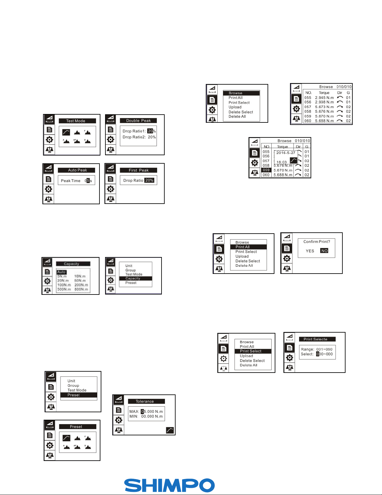
5.4 Test Mode
Change the mode of operation between the six modes. Press
“MODE/UP” or “DOWN” keys to select. Press “ZERO/EXIT” to
cancel or “MENU/ENTER” to confirm and exit. This adjustment
can also be changed at the home screen display by simply press-
ing “MODE”. First Peak Mode will display a drop ratio setting
menu. This drop ratio actives the first peak recording. Auto Peak
Mode will display a Peak Time setting menu. This resets the peak
value after programmed time has elapsed. Double Peak Mode
will display a dual drop ratio settings menu. This will enable two
separate peak values to be recorded.
5.5 Capacity (TTC-E Only)
The TTC-E with external sensor when set to Auto, the display will
automatically detect the proper range of the sensor. If any uncer-
tainty or in special circumstance, you may select the sensor range
in the list.
5.6 Preset
In the Preset menu, program high and low limit values to enable
ok/ov testing. The lower limit value cannot be greater than the
upper limit value, and neither limit value can be greater than 110%
of the rated capacity. Select proper mode to have presets active.
Press “MODE/UP” to adjust the value, touch “SAVE/PRINT” to
shift to the next position. Press “ZERO/EXIT” to cancel; touch
“MENU/ENTER” to confirm and exit.
4
6. MEMORY
In the Memory menu, the user can browse, delete, or print the
data.
6.1 Browse All
The data will be displayed. Touch “MODE/UP” or “DOWN” keys to
go to the next position. Touch “MENU/ENTER” to see additional
details of the data. Touch “ZERO/EXIT” to go back.
6.2 Print All
In the Print All Menu the data saved in memory can be output
to a printer through the serial port RS232 connection.
(See 10.3 RS232 in Communications section for more informa-
tion)
6.3 Print Selected
In this menu, select the data range to print. Touch “MODE/UP” to
adjust the value, touch “SAVE/PRINT” to shift to the next position.
Press “ZERO/EXIT” to cancel; touch “MENU/ENTER” to confirm.
1.800.561.8187
-Direct.ca
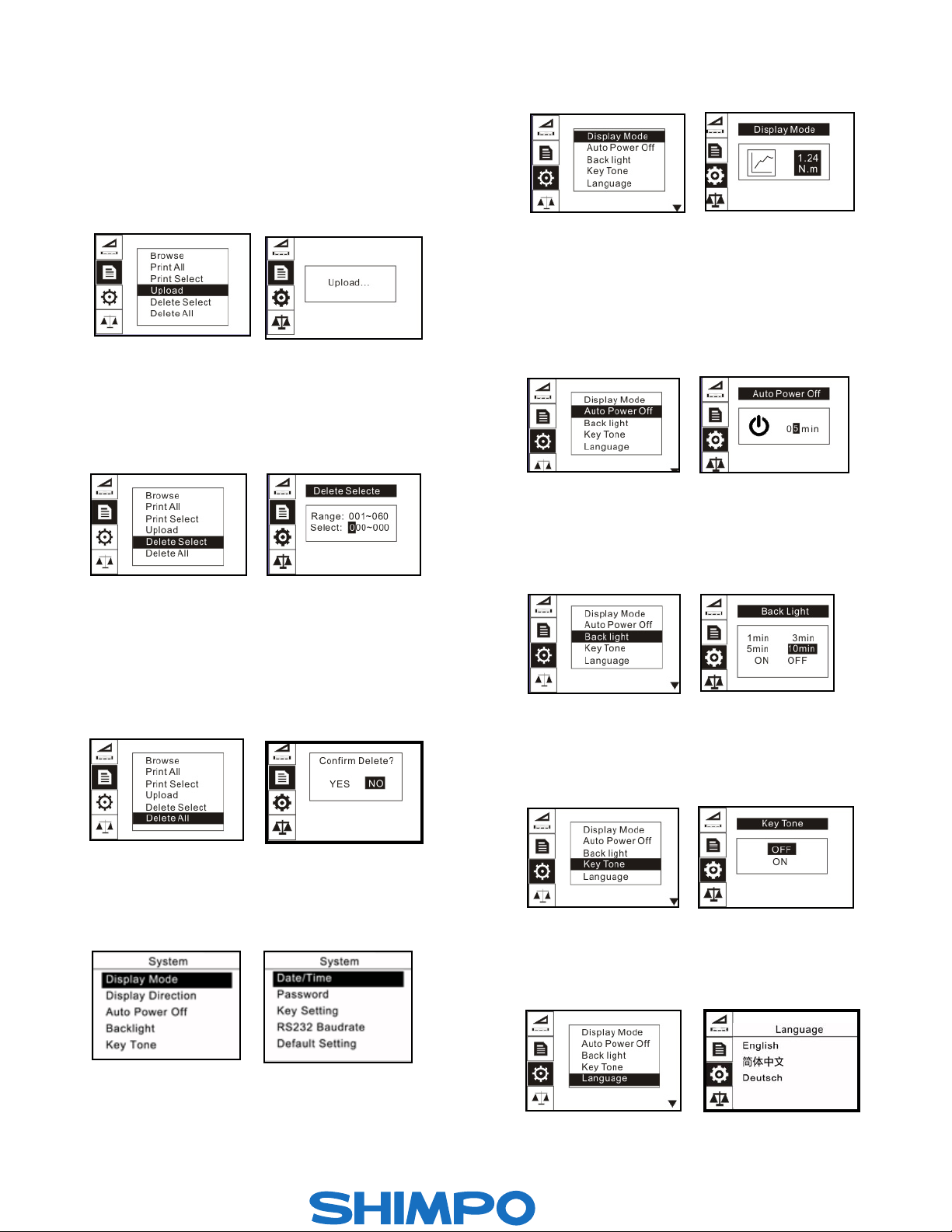
6.4 Upload
1. Choose in EDMS software the ‘Upload Memory Data
From Gauge’ selection.
2. On the TTC screen, select Upload. The screen should display
‘Upload…’ as shown below.
3. While ‘Upload…’ is visible on the screen, click ‘Start
Acquisition’ on the EDMS software.
4. Data should populate the table on the right hand side of the
software screen.
6.5 Delete Selected
Select the range of data to be deleted. Touch “MODE/UP” to ad-
just the value. Press “SAVE/PRINT” to shift to the next position.
Touch “ZERO/EXIT” to cancel; touch “MENU/ENTER” to confirm.
6.6 Delete All
In this menu, a prompt will appear. All data will be deleted by
selecting “YES” and canceled by selecting “NO” or pressing
“ZERO/EXIT”.
7. SYSTEM
Under the System menu, several parameters may be set.
5
7.1 Display Mode
Two display modes may be selected: Digital and Graphic.
7.2 Auto Power Off
To maximize battery life, the power can be set to shutdown after
non-use. The time can be set in this menu. The range is 01-99
minutes. When set to “99” the gauge will never turn off. Touch
“MODE/UP” to adjust the value, touch “SAVE/PRINT” to shift to
the next position. Press “ZERO/EXIT” to cancel; Push “MENU/EN-
TER” to confirm and exit.
7.3 Backlight
Under this menu, the backlight can be set to ON, OFF or have an
auto shutdown time. Touch “MODE/UP” or “DOWN” keys to shift
to the next position. Press “ZERO/EXIT” to cancel. Press “MENU/
ENTER” to confirm and exit.
7.4 Key Tone
Turn the key sound ON or OFF. Touch “MODE/UP” or “DOWN”
keys to shift to the next position. Touch “LOG” to cancel; Press
“MENU/ENTER” to confirm and exit.
7.5 Language
Select between English, German and Chinese.
1.800.561.8187
-Direct.ca
This manual suits for next models
9
Table of contents
Other Nidec-Shimpo Test Equipment manuals


Popular Test Equipment manuals by other brands


Redtech
Redtech TRAILERteck T05 user manual

Venmar
Venmar AVS Constructo 1.0 HRV user guide

Test Instrument Solutions
Test Instrument Solutions SafetyPAT operating manual

Hanna Instruments
Hanna Instruments HI 38078 instruction manual

Kistler
Kistler 5495C Series instruction manual

Waygate Technologies
Waygate Technologies DM5E Basic quick start guide

StoneL
StoneL DeviceNet CK464002A manual

Seica
Seica RAPID 220 Site preparation guide

Kingfisher
Kingfisher KI7400 Series Training manual

Kurth Electronic
Kurth Electronic CCTS-03 operating manual

SMART
SMART KANAAD SBT XTREME 3G Series user manual

Agilent Technologies
Agilent Technologies BERT Serial Getting started