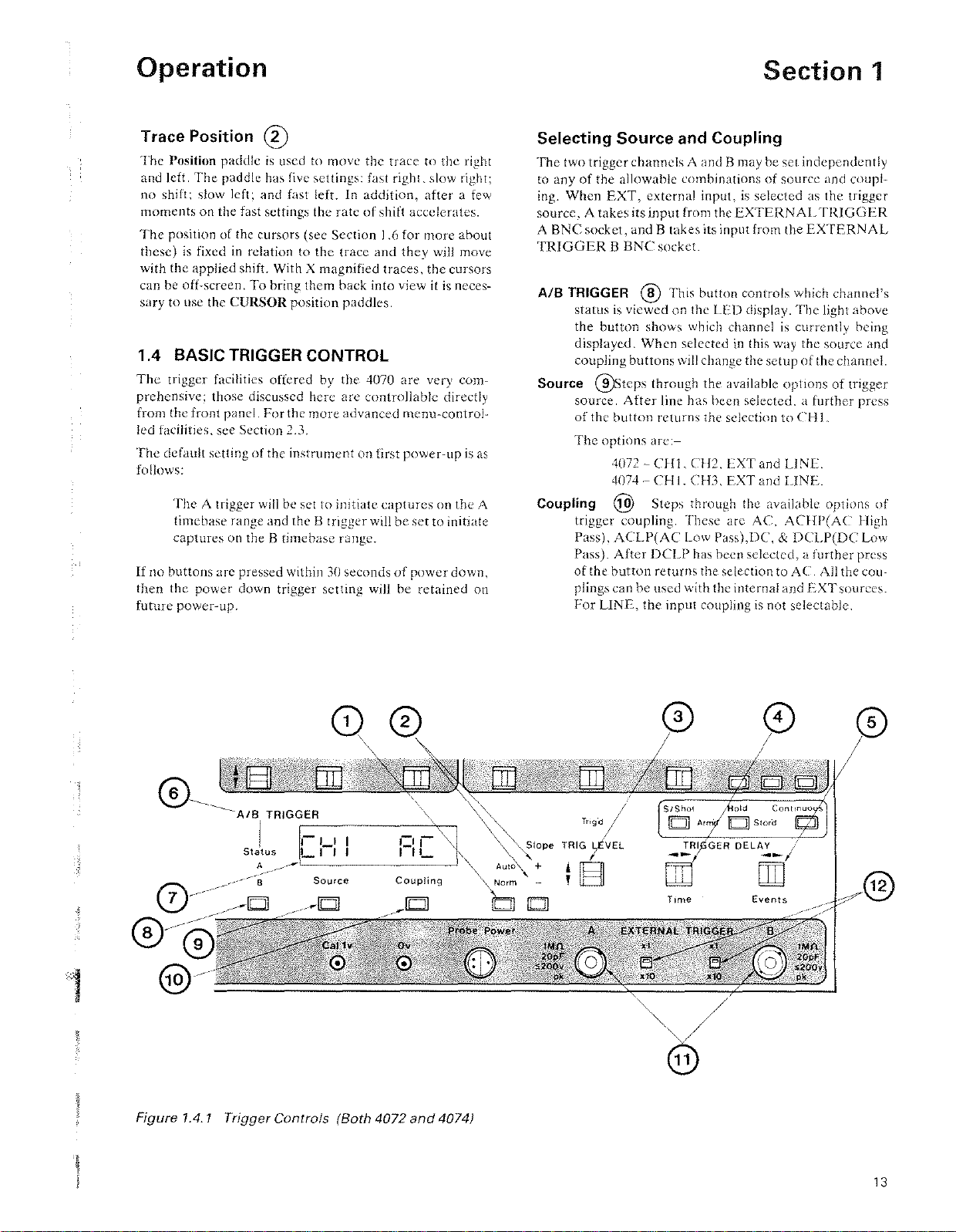
1
Operation
shown in front
of
the
attenuator
setting
when
variable
is
used.
Also.
when switching
between
Cal
and
Uncal
the var-
iable
setting
is
memorised
so
that
the
'Uncal'
ratio
can be
recalled.
Example
screen display:
Channel
1
is
set
to
a sensitivity
of
5 volts per
screen division.
C2>20m
V
Channel2
is
uncalihrated
and
the
attenuator
is
set to a reduced sensitivity. (i.e.
greater
than
20mV
per
screen division.)
The
status
of
the Step/Var
button
is
indicated
by the illumi-
nated
letters
above the
button.
Depending
upon
this,
the
VOLTS/DIV paddle will
operate
as
follows:
Cal
When
Cal
is
illuminated the
paddle
steps
the
attcnuator
through the discrete
calibrated
ranges
from
2mV
to
SV
per
screen
division in 1, 2, 5 steps.
With a
xlO
probe the ranges arc 20mV to 50V per
division at the probe input.
Uncal
The
coarse setting
of
the
attenuator
remains
unchanged,
but a variable gain
is
applied to the input
signa!. This gain has a range
of
l
to
about
0.4.
Thus.
with an initial setting
of
l
V,
the actual sensitivity of
the channel could be set
by
the
paddle
to anywhere
between
1V and 2.5V
per
division.
Note:
If
the
Gould
?836
x10
probe
is used,
it
will
be
detected
and
the
correct
sensitivity
will
be
displayed.
Position
®
The
Position paddle controls the vertical position
of
the
trace(s) for its channeL
It
has
the
following settings: Fast
up,
slow
up.
no
shift, slow down
and
fast down.
If
either
of
the
A
orB
Post
Storage
lights
are
lit, then the
Position
paddle
will apply
'post~storage
shift' to the relevant
trace(s).
The
paddle will move the trace in the
same
way
as
before.
When
the light
Is
off, the trace will
return
to its orig-
inal vertical position. This shifted position
is
memorised
and
can he recalled later by switching the light on again.
When
post~storagc
shift
is
used.
any
part
of
the trace which
would have
been
off~screen
at
the
ADC
limits will be
replaced by a horizontal line.
Post
Storage
(j)
The
three
PostStorage buttons. Hold, A
and
B,
arc
used for
freezing a trace and determining which
traces
may he
affected by the Position paddle:
Hold
Freezes
the trace on the screen the
moment
it
is
pres~
sed. In dual timcbase
mode,
both
traces
will be held.
It
is
not
possible to have
one
timcbase held whilst
keeping
the
other
one live.
A
B
Section
1
Pressing this
button
switches the A light on and off.
When the A light
is
illuminated, the Position
paddle
will add post-storage shift
to
the A trace.
Pressing this
button
switches the B light on and off.
When the B light
is
illuminated. the Position
paddle
will add
post~storagc
shift to the B trace.
Note:
Post-storage
shift
is
only
available
on
live traces
when
in
dual
timebase
mode,
when
it
is
useful
for
pro-
ducing
trace
separation.
Post-storage
shift
may
be
added
to
traces
in
single
timebase modes,
but
only
when
held.
Cursors@
The
cursors may be called
onto
any channel
by
pressing the
respective
channel's
Cursor
button.
If
only one timcbase
is
in
usc then the cursors will go
onto
the only displayed trace.
In
dual timebase
mode.
the cursors
will
initially
appear
on
trace
A:
a second press
of
the button will transfer them to
the B trace. A
third
press of the button switches the cursors
off.
For
a full description
of
cursor
operation.
sec Section 1.6.
1.3 HORIZONTAL POSITION AND TIMEBASE
The
controls discussed in this section allow the trace to be
moved sidew;Jys. magnified (i.e. stretched). and observed
at widely varying sweep rates, allowing signals
of
greatly
differing characteristics to be examined with equal ease.
Timebase
Settings
G)
The
two timebases which
arc
available for the input signal
arc set by the A
and
B
'TIME/DIV'
paddles. As with all the
paddles. these
arc
five position switches; they control the
rate at which the timebase
is
changed.
Moving
either
of
the
paddles to the left reduces the sweep
speed (acquisition
rate)
forth
at trace.
When
20
seconds
per
division
is
reached,
further
leftward presses will be ignored.
Moving the
paddle
to
the right increases the sweep speed,
up to
:1
maximum
of
20ns/div (sec
'Equivalent
Time
Sampl-
ing' below).
The
paddles
change the timebasc in 1, 2, 5
steps.
One
of
the special features
of
this oscilloscope
is
its ability
to display the
input
signals alternately on two
independent
tirnebases.
For
example,
it
is
permissible to display the A
trace with its time
base
set to lms/div and then display the B
trace with its timebase
set
to 20,us/div. Visually of course,
the alternation
is
so fast that no flickering
is
visible.
Note: The fastest
non~ETS
(see
below)
capture
rate is
250ns
per
division.
There is no
200nsldiv
range.
Equivalent
Time
Sampling
The
three
fastest timebase ranges, 100, 50 and 20ns/divi-
sion,
arc
produced by Equivalent Time Sampling,
or
ETS.
11
Artisan Technology Group - Quality Instrumentation ... Guaranteed | (888) 88-SOURCE | www.artisantg.com