Grizzl-E Mini User manual

GRIZZL E
EV Charger
MINI
™
User manual and installation guide

Model Numbers:
• GRM-14-18-PB
Grizzl-E Mini
User Manual
Version 1.1

Grizzl-E EV Charging Station – Mini Edition
The Grizzl-E Mini Edition is the smallest, most versatile, portable EV charging station available
on the market, made in Canada and built to withstand the toughest elements.
The Grizzl-E Mini Edition comes exclusively with a sleek, portable design and the ability
to set maximum amperage via Wi-Fi connection. Internal design and components of the
charger have been selected to provide maximum operational life of the device and be able to
withstand the elements.
Grizzl-E Mini provides up to 10 KW of power to your vehicle and can be set to multiple current
ratings for 240V and 120V outlets.
IMPORTANT SAFETY INSTRUCTIONS
This document contains instructions and warnings that must be followed when installing
and using the GRIZZL-E Mini Electric Vehicle Supply Equipment (EVSE). Before installing or
using the EVSE, read this document including any WARNING and CAUTION symbols.
Warning: risk of personal injury
Warning: risk of electric shock
Warning: risk of fire
Caution: risk of damage to equipment
The symbols used have the following meaning:
• This document provides instructions for the charging station and should not be used for
any other product. Before installation or use of this product, review this manual carefully
and consult with a licensed contractor, licensed electrician, or trained installation expert to
ensure compliance with local building codes and safety standards.
• Consult a licensed electrician to ensure that you can safely install and use this product.
• Ensure that the materials used, and the installation procedures, follow local building codes
and safety standards.
• The information provided in this manual in no way exempts the user of responsibility to
follow all applicable codes or safety standards.

Contents
OVERALL WARNINGS & CAUTIONS........................................................................... 5
Product Specications .............................................................................................. 6
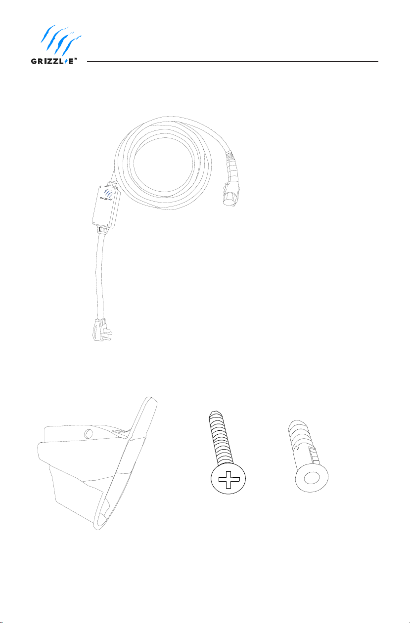
Introduction and Unpacking ................................................................................... 7
Installation Planning and Service Wiring: .............................................................. 8
Electrical Source Requirements ................................................................................... 8
Grounding Instructions .................................................................................................8
Grizzl-E Mini Multiple Voltage Ratings..........................................................................8
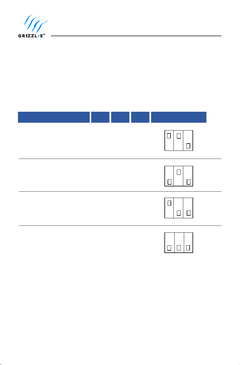
240V Outlet Settings .................................................................................................. 9
Maximum Current Output ............................................................................................ 9
Adjust Maximum Current Through DIP Switches.......................................................9
Adjust Maximum Current Through Web Browser....................................................11
Charging Status Indicators and Buzzers - 240V .......................................................12
120V Outlet Settings ................................................................................................ 13
Adjust Maximum Current Through Web Browser....................................................13
To set the Maximum Current ....................................................................................13
Charging Status Indicators and Buzzers - 120V .......................................................14
Charger Error Modes and Troubleshooting .......................................................... 15
Check EVSE Status ........................................................................................................15
EVSE Status....................................................................................................................16
Self-Monitoring and Recovery (Auto Restart) ...........................................................16
Troubleshoot EVSE Errors............................................................................................16
EasyEvPlug Holster and Cable Management System .......................................... 18
Operation ................................................................................................................. 19
Connect and Charge ....................................................................................................19
Stop Charging ...............................................................................................................19
General Product Care and Use Information ........................................................ 20
Warranty................................................................................................................... 21

5
CAUTION: The service wiring in this section are specific to North
America only. Before installing the Charging Station, identify the
type of utility service connection onsite. If unsure about the type of
connection available at the service panel, contact your utility service
provider.
Repair and Maintenance Clause
• All United Chargers products do not require routine maintenance however, periodic
inspections should be conducted to ensure that all parts remain in good working order
and no damage exists.
• Do not attempt to open, disassemble, repair, tamper with, or modify any components of
the products. Contact United Chargers for any repairs.
• Read all the instructions before using this product.
• Children should not use this device.
• Do not put fingers into the EV connector.
• Do not touch live electrical parts.
• Do not use this product if the flexible power cord or EV cable is ragged, has broken
insulation, or any other signs of damage.
• Improper connection of the equipment grounding conductor can result in a risk of electric
shock. Check with a licensed electrician if you are in doubt as to whether the product is
properly connected and grounded.
OVERALL WARNINGS & CAUTIONS
Basic precautions should always be followed when using electrical products,
including the following:
WARNING: This equipment is intended only for charging vehicles
that do not require ventilation during charging. Please refer to your
vehicle’s owner’s manual to determine ventilation requirements.

6
Product Specications
United Chargers GRIZZL-E™ Electric Vehicle Charging Station (EVSE)
Description Specications
Model Number GRM-14-24-PB
Connector EVSE Level SAE J1772; AC Level 2
Electrical Circuit / Input Power
Requirements
Dedicated Single Phase 208-240VAC 50/60 Hz. Branch
Breaker: Double pole
OR
Dedicated Single Phase 110-120VAC 50/60 Hz.
Output Ratings 240V Outlet
40A; 9.6kW with 50A Circuit Rating
32A; 7.68kW with 40A Circuit Rating
24A; 5.76kW with 30A Circuit Rating
16A; 3.84kW with 20A Circuit Rating
120V Outlet
15A; 1.8kW with 18A Circuit Rating
12A; 1.44kW with 15A Circuit Rating
10A; 1.2kW for 12A Circuit Rating
8A; 0.96kW for 10A Circuit Rating
Input Power Connection Plug in NEMA 14-50
Installation Rating NEMA 4, Indoor/Outdoor Rated
Operational Ratings Temperature -22F to 122F (-30C to 50C)
Humidity: 95% non-condensing
Overall Dimensions Length: 175mm (6.9in)
Width: 80mm (3.1in)
Height: 60mm (2.4in)
Display and Indicators LED Charge Status Indicator
(Amperage Setting, Ready/Charging, Charging Fault)
Charge Cable Length 24ft (7.3m)

7
Introduction and Unpacking
EasyEVPlug
Holster
Phillips Head Screws
(x4)
Anchor (x4)
MINI
Charging Station with Input and Output Cable

8
Grizzl-E Mini Multiple Voltage Ratings
Grizzl-E Mini has the ability to work with either a 240V or 120V dedicated circuit.
Grizzl-E Mini will automatically detect the outlet power and will adjust settings when the input
cable is plugged into the outlet.
To use Grizzl-E Mini with 120V outlet, use a NEMA 5-15P Male to 14-50R Female, 120V 15A
Adapter.
Installation Planning and Service Wiring:
CAUTION: To reduce the risk of fire, connect only to a circuit
provided with the minimum branch circuit overcurrent
protection requirements in accordance with the National
Electrical Code ANSI/NFPA 7- and the Canadian Electrical Safety
Code, Part 1, C22.1. If you are unsure if your circuit meets these
requirements consult a licensed electrician.
Grounding Instructions
The charging station must be implemented equipment grounding through a permanent
wiring system or an equipment grounding conductor. Use a cable with a dedicated grounding
conductor connected to the equipment ground terminal block.
Prior to using Grizzl-E Mini ensure the electrical source that can support the following Input
Requirements for the Charging Station Per local Electrical Safety Code requirements:
• 240VAC or 120VAC Dedicated Circuit
• A Double Pole Circuit Breaker of the circuit rating must be used.
• The Charging Unit has a built in GFCI protection; do not provide any additional GFCI
protection upstream of the charging unit.
Electrical Source Requirements

9
240V Outlet Settings
Maximum Current Output
The GRIZZL-E Mini charging station features the ability to adjust the maximum current output.
Requirements govern that only 80% of the circuit rated load may be utilized. The Grizzl-E Mini
can support current output of 50A, 40A, 30A, or 20A Dedicated Circuit ratings as follows:
Circuit Rating Maximum Charging Station Output
50A 40A (9.6 kW)
40A 32A (7.68 kW)
30A 24A (5.76 kW)
20A 16A (3.84 kW)
At 240V the Maximum Current Output is governed by the DIP switches on the PCB.
The DIP switch is a 3-position switch located at the top of the PCB.
Adjust Maximum Current Through DIP Switches

10
DOWN DOWN
DOWN
DOWNDOWN
UP
UP
Maximum Current Output DIP 1 DIP 2 DIP3 DIP Switch Setting
40A Maximum Current Output
(Factory Default Setting)
32A Maximum Current Output
24A Maximum Current Output
16A Maximum Current Output
Down
DOWNDOWN
UP UP
To adjust the Maximum Current Output Setting DIP Switches:
1. Ensure the Charging station is unplugged. Place the Charging Station on a at surface with
the front cover facing up.
2. Use a Phillips Head screwdriver to remove the front cover by removing the 4 screws at
each corner of the charging station.
3. Using a non-conductive object adjust the Maximum Current Output using the following
combination of DIP switch settings:
4. Replace the enclosure lid by tightening the 4 screws at each corner

11
1. Plug in the Charger.
2. Open the Wi-Fi settings on your smart phone.
3. Select the network UC_Mini_Grizzle.
4. Open your mobile browser.
5. Enter the IP address 192.168.0.116 into the browser search bar.
6. A webpage will load with selection for the maximum current.
Adjust Maximum Current Through Web Browser
The Grizzl-E Mini Allows you to change the adjustable maximum circuit through the Wi-Fi
connected feature.
To set the Maximum Current :
7. Select the Parameters button.
8. Select the voltage based on the circuit rating.
Note: The Web Browser Access Point is not able to set Maximum Current above the DIP
switch settings. Maximum Current settings equal to or less than the DIP switch settings will
show on the browser page.

12
Charging Status Indicators and Buzzers - 240V
LED Indicator
32A Maximum Power
Fault
Charging
Ready /Not Charging
40A Maximum Power
24A Maximum Power
16A Maximum Power
Amperage Settings)
Maximum Amperage Indicator
LED Indicator Description Definition
Definition
Description
Blue
Green
White
Yellow
Red Flashing
Blue/White/
Yellow/Green
Steady
Blue/White/
Yellow/Green
Flashing

13
120V Outlet Settings
To set the Maximum Current
1. Plug in the Charger.
2. Open the Wi-Fi settings on your smart phone.
3. Select the network UC_Mini_Grizzle.
4. Open your mobile browser.
5. Enter the IP address 192.168.0.116 into the browser search bar.
6. A webpage will load with selection for the maximum current.
Adjust Maximum Current Through Web Browser
To use Grizzl-E Mini with a 120V Outlet you will need a NEMA 5-15P Male to 14-50R Female,
120V 15 Amp adapter. Grizzl-E Mini will automatically detect a 120V outlet.
When Plugged into a 120V Outlet the Maximum Current is set through a web browser. The
DIP Switch settings will not affect 120V Amperage.
7. Select the Parameters button.
8. Select the voltage based on the circuit rating.

14
Charging Status Indicators and Buzzers - 120V
LED Indicator
12A Maximum Power
Fault
Charging
Ready /Not Charging
Blue/White/
Yellow/Green
Steady
Blue/White/
Yellow/Green
Flashing
15A Maximum Power
10A Maximum Power
8A Maximum Power
Charging Indicator (All Amperage Settings)
Maximum Amperage Indicator
LED Indicator Description
Definition
Definition
Definition
Blue
Green
White
Yellow
Red Flashing

15
Grizzl-E Mini provides real time information on the status of the EVSE and charging session.
To check the status of the EVSE follow the procedure to load the webpage on page 11.
EVSE Status displays at the bottom of the page.
To view real-time charging status and error notications.
1. Plug in the Charger.
2. Open the Wi-Fi settings on your smart phone.
3. Select the network UC_Mini_Grizzle.
4. Open your mobile browser.
5. Enter the IP address 192.168.0.116 into the browser search bar.
6. A webpage will load with selection for the maximum current.
7. Select the Parameters button.
Charger Error Modes and Troubleshooting
Check EVSE Status

16
In the event of a Red Flashing Indicator Light, follow the procedure to check the “Check EVSE
Status” on page 15.
Check the error mode under EVSE State:
Troubleshoot EVSE Errors
Over Current:
1. Unplug the charging connector from your EV
2. Turn off the charging station power by switching the upstream circuit breaker to the “OFF”
position
3. Wait 1-2 minutes and then switch the upstream circuit breaker back to the “ON” position
4. Confirm the Fault light is no longer present.
5. Ensure that Maximum Current Output settings are correct for the circuit breaker.
6. Ensure vehicle settings do not draw more current than the Maximum Current Output.
Self-Monitoring and Recovery (Auto Restart)
When a charging session is interrupted due to an Over Current (OC) error condition, it will
attempt to recover every 30 seconds until the OC condition is resolved. The charging station
will automatically restart after recovery from the OC condition.
Description Specications
CPU Temp The internal temperature of the CPU.
Relay Temp The internal temperature of the charging relay.
AC Current The current being supplied to the vehicle.
AC Voltage Measurement of the power supply voltage.
Charging Time: The amount of time elapsed in the charging session.
EVSE State The present status of the EVSE. See “Charger Error
Modes and Troubleshooting” on page 15 for more
information
EVSE Status

17
Under Voltage:
1. Unplug the charging connector from your EV.
2. Wait 1-2 minutes and then switch the upstream circuit breaker back to the “ON” position
3. Confirm the Fault light is no longer present.
4. Consult an electrician about the supply voltage if the error persists.
Missing Diode:
1. Unplug the charging connector from your EV.
2. Wait 1-2 minutes and then switch the upstream circuit breaker back to the “ON” position
3. Confirm the Fault light is no longer present.
4. Contact United Chargers Technical Support if the error persists.
Ground Fault
1. Unplug the charging connector from your EV.
2. Wait 1-2 minutes and then switch the upstream circuit breaker back to the “ON” position
3. Confirm the Fault light is no longer present.
4. Contact United Chargers Technical Support if the error persists.
Over Temperature:
1. Unplug the charging connector from your EV.
2. Unplug the EVSE from the outlet.
3. Allow 1 hour for interior electronics of Mini Grizzl-E to cool down.
4. Plug the EVSE back into the outlet. Conrm the fault light is no longer present.
5. Keep Mini Grizzl-E out of the sun or warm places when charging. Touch surface of
enclosure to check if unit is too hot.

18
EasyEvPlug Holster and Cable Management System
The EasyEVPlug™ Holster or Tesla EasyEVPlug™ Holster is the new innovative method to
protect your plug and manage your cord. It has the following features:
• No need to aim – flawless plug even in the dark.
• Your EV holster will always be in a convenient location.
• Saves space – special angle for less wall clearance.
• Integrated cable management – holds up to 25 feet of cable.
The EasyEvPlug holster can be installed at any location near the charging station.
(x4)
1. Hold back of holster against the mounting
surface. Fasten Phillips head screws through
back holes. Use anchors if attaching directly to
drywall.
2. Insert charging connector into holster.
3. Wrap cable on top of EasyEvPlug.

19
Operation
Connect and Charge
Stop Charging
Insert the charging Connector into the EV and ensure the connector is fully seated/locked in
place. Once complete, the charging session will begin.
1. Unplug the charging station by pressing the connector button and removing the Charger
Connector from the EV (once the connector button is depressed, the charging session
terminates immediately).
2. Return the connector to the holster.
Figure 3-1. Connect the charging plug to the EV

20
General Product Care and Use Information
The exterior of the charging station is designed to be waterproof and dust proof (NEMA 4
Outdoor Rated). However, periodic cleaning may be required, depending on local conditions.
To ensure proper maintenance of the charging station, follow these guidelines:
• To avoid damaging the finish of the products, only use an automotive grade soft cleaning
cloth with soap and water to remove accumulated dirt and dust. Do not use cleaning
solvents to clean any of the product components.
• Despite the water resistance of the enclosure, submerging the unit under water is not
recommended.
• Ensure the charging connector is put back in the holster after charging to avoid damage.
• Ensure the power cable is stored on the charging station after use to avoid damage.
• If the power cable or the charging connector is damaged, turn off the charging station
supply circuit breaker, do not use the charging station, and Contact United Chargers
Customer Support for replacement parts.
• When moving or lifting the unit, always grasp and carry by the charging station body.
Never attempt to lift, move, or carry the unit by any of the electrical cables. Improper
handling may cause damage to the unit.
This manual suits for next models
1
Table of contents
Other Grizzl-E Batteries Charger manuals

Grizzl-E
Grizzl-E United Chargers GRS-14-24-P User manual

Grizzl-E
Grizzl-E GR1-6-18 Series Installation and operating instructions

Grizzl-E
Grizzl-E GR1-6-18-R Installation and operating instructions

Grizzl-E
Grizzl-E United Chargers GRS-14-24-P User manual

Grizzl-E
Grizzl-E Ivy Home User manual

Grizzl-E
Grizzl-E Smart Connect Classic Installation and operating instructions

Grizzl-E
Grizzl-E Mini GRM-14-24-PB User manual

Grizzl-E
Grizzl-E United Chargers GRS-6-24-P User manual

Grizzl-E
Grizzl-E Extreme Edition Installation and operating instructions

Grizzl-E
Grizzl-E DUO Installation and operating instructions