• Solaris powerhead and reactor
• Four self tapping screws
• Two wire nuts / 40 VA Transformer.
• Viewport (snap in)
• 24VAC Power cord
• UVC warning label
• Replacement lamp log sheet
• Viewport label
• Warranty card
• Ductboard plate / sealing tape
• Product gasket
Package Contents:
Safety Precautions:
It is recommended that this unit be installed and maintained by a trained technician.
WARNING: UV Hazard. Always protect eyes from ultraviolet light. NEVER look at UV lamps in
operation. Unplug or disconnect power before re-lamping or servicing.
WARNING: Severe eye damage or temporary blindness may occur.
WARNING: DO NOT operate outside of air handler. Mount product in preferred
location rst.
WARNING: No openings should be allowed which would give direct line-of-sight to the UV light.
Note: In the event of accidental breakage or replacement of the ultraviolet lamp, please ensure that
the lamp is disposed of in accordance with local and state environmental laws regarding uores-
cent lamps containing mercury.
Notice: All wiring inside of the air handler in direct line of site of the UV lamp must be shielded
with aluminum foil tape or equivalent non-combustible material. When installing this unit, select
a mounting location that prevents ultraviolet light exposure to synthetic or other plastic com-
ponents with unknown resistance to ultraviolet light. Ultraviolet light may cause color shi or
structural degradation of plastic internal components.
Mechanical installation
1. Determine a location for the Solaris system. Mount the unit on the exit or supply side of the
HVAC system and before the ductwork branches o.
2. Separate the power module from the mounting plate.
3. Note the orientation of the power module as it connects in only one direction.
4. Mark a 4” round opening (or use the end of the PCO chamber to mark the area) on the air duct
and cut the hole needed for the insertion of the advanced photocatalytic chamber.
5. read supplied gasket over PCO module and attach to mounting plate. (Seals against
air duct.)
6. Insert the mounting plate / PCO module into opening and attach to duct with two supplied self
-tapping screws in the lower le and upper right
(only).
7. Adjust purication level. (See next page)
8. Place the power module on the unit aligning holes in tabs with holes in mounting plate (upper
le /lower right).
9. Secure the power module to the mounting plate with the remaining two self-tapping screws.
Adjusting the Purication level
e Solaris is a universal air purier with a patented
design that provides adjustability to the advanced
photocatalytic process for a variety of treated space sizes.
When setting up your equipment, adjust the purication
level (under electronics cover) to the appropriate position
based on the square footage Fine adjustments may be
required depending upon household living characteristics.
Lamp Replacement Procedure:
e UV lamp is shipped installed in the equipment and should
be replaced during an annual service. To replace the UV lamp
follow the steps below:
1. Unplug power cord and remove power module. (See Fig. 1)
2. Note the position of the Photon Clarier and pull adjustment
bar to its full-out position. (See Fig. 2)
3. Remove lamp screws and pull lamp out of PCO module.
(See Fig. 3)
4. Install new lamp and fasten with lamp screws.
5. Set the Photon Clarier to its noted setting.
6. Place the power module on the unit and fasten.
7. Plug in power cord.
Fig. 1
Fig. 2
Fig. 3
Installing EZ-Light 6P (Optional)
1. Turn o power to system being upgraded by turning o, disconnect or turning o breaker to the
system.
2. Remove blank plug by squeezing it from the inside of the electrical enclosure with a pair
of pliers and pushing it out of the enclosure.(is step not required on EZUV product)
3. Disconnect the 6 pin connector in line with the lamp connector.
4. Connect the supplied ‘‘Y’’ connector to the 6 pin connector in the system and connect
the lamp connector into the ‘‘Y’’ connector.
Note: All the connectors are specic to its location and can be connected incorrectly.
5. Plug the lamp connector fully onto the installed lamp. Be sure the four pinholes are orientated
properly to the four matching pins on the lamp.
Common
120
208
240
277
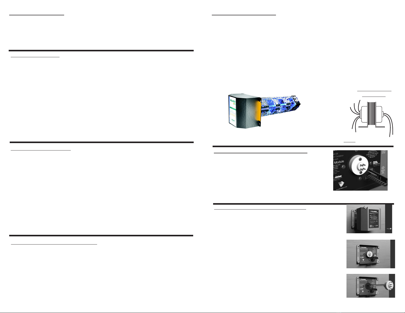
24 VAC
Electrical installation
is product operates on 24 VAC must be connected to a dedicated minimum 40va trans-
former supplied
1. Disconnect power supply before beginning installation to prevent electrical shock or
equipment damage.
2. Connect secondary voltage. Refer to voltage color or terminal coding on transformer
for proper wire combination. On terminal type transformer, be sure that no exposed wire
can come in contact with any terminal.
3. Connect primary voltage. Refer to voltage color coding on transformer for proper wire
combination. See Fig. 1 for connection and installation.
4. Tape or protect all unused exposed wire separately to avoid a possible electrical short.
5. Check installation and reconnect power supply for proper operation.
Typical multi-tap
transformer
Fig. 1


