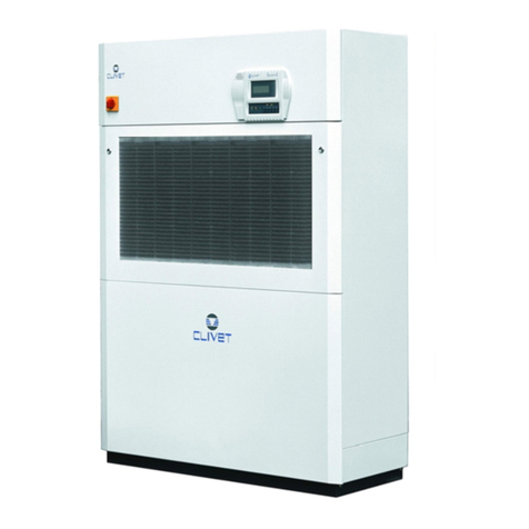
CLIVET HWM-2-XMi 140 User manual

HWM-2-XMi 140
MANUAL
FOR INSTALLATION,
USE AND MAINTENANCE
High Temperature Hydro Module for
VRF MV6R series

Dear Customer,
Congratulations for having chosen this product.
Clivet has been working for
years to offer the market systems able to assure maximum and long-lasting
wellbeing with high reliability, efficiency, quality and safety.
The company aim is that to offer its customers developed systems that assure the best comfort, reduce
energy consumptions and installation and maintenance costs for
the enti re life-span of
the system.
With this manual, we intend giving information useful throughout ali phases: from reception, to
installation, to use and even disposal, so that such a developed system meets the best installation and
use methods.
With kind regards and ... good reading!
CLIVETSpa
The data contained in this manual is not binding and may be changed by the manufacturer without
prior notice. AII reproduction, even partial, is PROHIBITED. Copyright -CLIVET S.p.A. -Feltre (BL) -ltaly

32

Page intentionally left blanck

MD19I-010AW(DZ)

Page intentionally left blanck

CONTENTS
2
3
4
01
04
04
05
06
07
07
08
Structural Dimensions
Center of Gravity
Installation Space
General Precautions about the Water System
Checking, Handling, and Unpacking the Unit
Installation Diagram
4.1
4.2
4.3
4.4
4.5
4.6
03
03
03
02
Introduction
Combinations and Options
Application Scope of the Manual
Specification
3.1
3.2
3.3
3.4
5
Accessories
GENERAL SAFETY PRECAUTIONS
1
02
02
Meanings of Warnings and Symbols
1.1
DEFINITIONS
OVERVIEW
UNIT APPEARANCE
23
23
Final Check
Test Run
10.1
10.2
10 FINAL CHECK AND TEST RUN
23
11 MAINTENANCE AND SERVICE
UNIT INSTALLATION
15
6APPLICATION EXAMPLES
22
7PUMP MODEL SELECTION
23
9DOMESTIC HOT WATER TANK
22
8SELECTION OF EXPANSION TANK VOLUME AND
PRESET PRESSURE

01
Accessories
Name Qty Shape Purpose
Installation Manual
User Manual
Connecting pipe assembly
(Including safety valve)
Water discharge hose
Wired controller
Water temperature sensor
Y-shaped filter
Network matching wire
Cable tie
1
1
1
1
1
1
1
1
6Fixing the wire and
magnetic ring
Connected to the water-inlet
pipe side
Detecting water tank
temperature
Connected to the outlet of
the drainage pan
Connected to the water-outlet
pipe side
Control the unit
Magnetic ring 2
M0WU00002-00

02
1 DEFINITIONS
2 General Safety Precautions
1.1 Meanings of Warnings and
Symbols
3.1 Introduction
Warnings in this document are classified according to
severity and the likelihood of occurrence.
Indicates an urgent danger, which may lead to
severe injury or death.
DANGER
Indicates a potential danger, which may possibly
lead to severe injury or death.
WARNING
Indicates a potential danger, which may lead to
mild or moderate injury. It can also be used to
warn you of unsafe behaviours.
Indicates a situation that may only cause
damage to the equipment or loss of property.
Indicates a useful hint or additional information.
NOTE
INFORMATION
i
Certain types of danger are indicated by special
symbols.
STATEMENT
Elctric shock
Danger of burning and scalding
Herein, the precautions are classified into the following
two types, which cover very important items. Please
read them carefully.
DANGER
Electric shock
Before removing the maintenance panel of the
electric control box or performing any
connections or touching an electric part, please
shut down all the power.
Do not touch any switches with wet hands. This
is to prevent electrical shock. Before touching an
electrical part, please shut down all related
power.
Wait 3 minutes after disconnecting power,them verify
DC voltage less than 42VDC at inverter test point
DC-BUS(CN52).Components may store a dangerous
electrical potential of 380VDC.Failure to follow this
warning could result in personal injury or death.
When the maintenance panel is removed, you
may easily touch the live parts. Therefore, when
you remove the maintenance panel, do not
engage in unattended installation or
maintenance.
DANGER
Do not touch pipes and internal parts.
Do not touch refrigerant pipes, water pipes or
internal parts during operation and immediately
after operation. Pipes and internal parts may be
hot depending on the operating status of the
unit.
If you touch pipes or internal parts, burning may
occur. It takes time for pipes and internal parts to
regain a normal temperature. To avoid injury, you
must wear protective gloves before touching
them.
3 OVERVIEW
This installation manual applies to high temperature
hydro module indoor unit. This appliance is intended to
be used by expert or trained users in shops, in light
industry and on farms, or for commercial use by lay
persons. The units is partial unit heat pump, complying
with partial unit requirements of this International
Standard, and must only be connected to other units that
have been confirmed as complying to corresponding
partial unit requirements of this International Standard.
when the product is used for comercial application. This
appliance is intended to be used by expert or trained
users in shops, in light industry and on farms, or for
commercial use by lay persons,the sound pressure level
is below 70 dB(A).
The hydro module is designed to operate indoors at
room temperature from 0 °C to 40 °C.
During heating or DHW, the unit can increase water
temperature from 25 °C to 80 °C.
M0WU00002-00

03
3.2 Combinations and Options
The Hydro Module unit can be connected to the V6R
ODU only.
The wired controller with an indoor constant temperature
function is the standard configuration of the unit, for unit
control.
3.3 Application Scope of the
Manual
3.4 Specification
This manual does not contain model selection and water
system design. Another chapter in this manual just
provides the precautions, hints, and tips about water
system design. Once the model is selected and the
water system is designed, the water system should be
connected to the unit. This document describes how to
conduct handling, installation, and connection for
connecting the water system to the Hydro Module unit.
For the articles beyond this manual, please read
the Installation Manual about the ODU. The
Hydro module’s User Manual describes how to
use the Hydro module.
INFORMATION
i
Rated
Water outlet : 45°C,
inlet 40°C
Outdoor air : 7C DB /
6C WB
kW 14
Heating
capacity
Rated
Water outlet : 45°C,
inlet 40°C
Outdoor air : 7°C DB
/ 6°C WB
kW 14
Heating
capacity
Colour
Height
Width
Depth
Polar white
795
450
300
mm
mm
mm
kg
Casing
Net
Dimensions
Plate heat
exchanger
Plate heat
exchanger
Type
Quantity
Plate
Type
Quantity
Plate
1
76
1
38
Ambient, Min-Max
Voltage Range, Min/
Max
Maximum running
current (MCA)
MFA
Power supply
Current
Amper
0~40
1-ph
50
220 ~ 240
± 10
%
16
20
A
A
Hz
V
°C
Unit Location
Installation
place
Water side
Heat
exchanger
Refrigerant
side heat
exchanger
Domestic Hot
Water
Operation
Range
Heating
Operation
Range
Refrigerant
oil
Sound
pressure level Nom.
Nom.
dB(A)
dB(A)
43
54
Sound
Power Level
Ambient, Min
Ambient, Max
Water Side, Min
Water Side, Max
Ambient, Min
Ambient, Max
Water Side, Min
Water Side, Max
°C
°C
°C
°C
°C
°C
°C
°C
-20
30
25
80
-20
43
25
80
Phase
Frequency
Voltage
Weight
Water Flow
Rate
Water circuit
Piping connections
diameter
(external groove)
mm 25.4 / 25.4
Design
pressure
Allowed water
pressure
R410a
R134a
Mpa 0.1~0.3
Mpa
Mpa
4.0
3.1
Type
Charge
Gas side diameter
Liquid side diameter
Charged volume
Type
kg
mm
mm
L
R-134a
1.2
12.7
9.52
0.4
FV50S
Unit
Packed unit
Minimum
Nominal
Maximum
63
71
1.2
2.4
2.9
kg
kg
m³/h
m³/h
m³/h
Refrigerant
Refrigerant
circuit
Note:
*Nominal heating conditions
inlet water temperature: 40 °C
water flow rate: 2.4 m3/h
Outdoor Temp. : 7°C DB/6°C WB
*The water circuit must use the closed circuit.
*Please do not use it as a drinking water.
* Due to continuing improvement, the above
specifications may be subject to change without notice.
* Please don't use the steel material for the water piping
material.*
* Please always make water circulate or pull out the
circulation water completely when not using it.
*Please do not use groundwater and well water.
M0WU00002-00

04
4.1 Structural Dimensions (unit: mm)
4.2 Center of Gravity (unit: mm)
4 UNIT APPEARANCE
795
779
300
525
485
450
105
165
155
Hydro module unit (top view)
165
795
105
165
300
200
450
525
200
M0WU00002-00

05
4.3 Installation Space
A
a
b
c
C
B
795100
100
795
100
100
Space
Air inlet
Air outlet
Space
Anti-vibration material
A
B
C
Hydro module unit
Space for installing piping (on the right side)
Space for installation and maintenance (in the front)
Flat washer
Anchor bolt
Spring washer
Nut
Anti-vibration material
Concrete base
Support
75(2-15/16)
3 or more screw
threads of the 2
bolts must be shown
General Precautions about Installation Sites
Select an installation site that meets the following conditions:
The floor that supports unit weight should be hard enough. The floor should be level to avoid vibration and noise.
The space around the unit should be wide enough for maintenance and repair. The space dimensions are as follows: a ≥ 400
mm; b ≥ 300 mm; c ≥ 600 mm. If double-layer installation is required, the upper and lower space between units should be
not less than 150 mm.
There should be enough space around the unit for ventilation.
If flammable gas leaks, ensure that there are no hazards that could lead to fire.
This unit is not designed to operate in an environment where explosions could occur.
Select the installation site according to the corresponding legal provisions. The noise should not affect any person. Carefully
select an installation site. Do not install the unit in an environment that is sensitive to sound, such as living rooms and
bedrooms.
If water leaks, the leakage should not cause damage to the installation site or the surroundings.
Take enough measures according to the corresponding legal provisions to deal with refrigerant leakage.
When the unit is installed in a small room, take measures to ensure that concentration of the leaking refrigerant cannot
exceed the allowed limit.
For applicances intended for use at altitudes exceeding 2000 m, the maximum altitude of use shall be stated.
H-Beam supporter
Concrete supporter
M0WU00002-00

06
4.4 General Precautions about the Water System
Check the following items before continuing installation:
Min. water pressure: 1 bar
Max. water pressure: 3 bar
Min. water temperature: 5°C
Max. water temperature: 80 °C
Install enough safety devices in the water loops to ensure that the hydro pressure does not exceed the maximum operating
pressure (3 bar).
Provide a drainage hole at all the low points of the system so that the water is completely drained from the water system
when you repair or maintain the unit. A drain valve has been installed at the water inlet to facilitate water discharge from the
unit's water system.
Ensure that you have provided a suitable water discharge pipe to the safety valve to prevent water from coming into contact
with any electrical part. A water discharge pipe has been provided with the unit.
You must deploy air outlets at all the high points of the system. The air outlets should be deployed at the places where they
can be easily maintained. A drain valve has been installed at the water outlet to facilitate air discharge from the unit's water
system.
Ensure that all the components installed on pipes on site can bear water pressure and water temperature.
You should use materials that are compatible with water and equipment in the system.
Anti-freezing protection of the water system:
Freezing may cause damage to the system. The ODU may be exposed to temperatures below 0 °C. You must prevent
the system from freezing.
All the internal water systems are insulated to prevent heat loss. On site, pipes should be fitted with insulating materials.
The unit is designed with an anti-freezing function. The unit uses a heat pump to prevent the entire system from freezing.
When the water temperature in the system decreases to a certain value, the unit will heat water. The anti-freezing
function will be disabled only when the water temperature rises to a certain value.
In the event of power failure, the anti-freezing function cannot protect the unit from freezing.
Using anti-freezing liquid in the water system is recommended, because power failure may happen when no one is
present.
Ensure that the water system is full of the ethylene glycol concentration provided in the following table, according to the
expected lowest outdoor temperature. When ethylene glycol is added to the system, device performance will be affected.
The following table lists the correction coefficients of the unit capacity, flow, and pressure drop of the system.
WARNING
In an airtight space, excessively high concentration of the refrigerant may lead to insufficient oxygen.
Do not climb, sit on, or stand on the unit.
Do not place any article or equipment on the top of the unit (top panel of the unit).
Do not install the unit in a workshop, for example, a construction site, because at construction sites, the equipment will be
covered in dust.
Do not install the unit in a highly damp site, such as a restroom. (The maximum relative humidity is 85%.)
When installing the unit, reserve enough space for the air inlet and air outlet. Do not obstruct them.
Ethylene Glycol
Quality of
glycol/%
0
10
20
30
40
50
1.000
0.984
0.973
0.965
0.960
0.950
1.000
0.998
0.995
0.992
0.989
0.983
1.000
1.118
1.268
1.482
1.791
2.100
1.000
1.019
1.051
1.092
1.145
1.200
0.000
-4.000
-9.000
-16.000
-23.000
-37.000
Freezing
point/°C
Cooling capacity
modification
Power
modification
Water
resistance
Water flow
modification
Modification coefficient
M0WU00002-00

07
4.5 Checking, Handling, and Unpacking the Unit
4.6 Installation Diagram
If ethylene glycol is not added, water must be discharged when power is cut off.
WARNING
Both ethylene glycol and propylene glycol are toxic.
The concentration mentioned in the preceding table cannot prevent freezing, but can prevent breaking caused by liquid
pressure.
WARNING
Remove the plastic packaging bag so that children cannot play with it. Children may face the danger of death by
suffocation if playing with the plastic packaging bag.
Propylene Glycol
Quality of
glycol/%
0
10
20
30
40
50
1.000
0.976
0.961
0.948
0.938
0.925
1.000
0.996
0.992
0.988
0.984
0.975
1.000
1.071
1.189
1.380
1.728
2.150
1.000
1.000
1.016
1.034
1.078
1.125
0.000
-3.000
-7.000
-13.000
-22.000
-35.000
Freezing
point/°C
Cooling capacity
modification
Power
modification
Water
resistance
Water flow
modification
Modification coefficient
When the unit is delivered, you must check the equipment and immediately report damage (if any) to the claims agent of the
carrier.
Put the packaged unit as close as possible to its final installation site to prevent damage during the handling process.
Check all the accessories of the Hydro module. (For details, see " Accessories" on page 1.)
K
J
I
H
G
FE
D
K
N
M
GL
M0WU00002-00

08
Liquid pipe (connected to the ODU)
Gas pipe (connected to the ODU)
Water discharge pipe (drainage pan)
Y-shaped filter
Access hole (for charging/discharging refrigerant)
Water discharge pipe (safety valve)
Safety valve
Discharge valve
Drain valve
Water inlet
Water outlet
D
D
E
E
F
F
G
H
H
I
J
K
L
M
M
N
N
32
130
80
42
80
135
218
348
192
248
5 UNIT INSTALLATION
INFORMATION
i
The unit should be installed by professional
installation operators. Material selection and
installation should conform to the corresponding
legal provisions.
Checking the main parts of the unit
To check the interior of the unit, open the top panel, front
panel, and rear panel first. After you open these three
panels, you can see the main parts of the unit. If you just
install or maintain the internal parts of the electric control
box, you need to open the front panel without needing to
open the top or rear panel
2
1
3
1
2
3
Top panel
Front panel
Rear panel
To open the electric control box and operate the interior
of the electric control box, open the electric control box
cover plate. To open the electric control box, you can
open the front panel without needing to open the top or
rear panel.
Danger: Electric shock
See "1.2 General Safety Precautions"
on page 2.
Danger: Do not touch pipes or internal
parts. See "1.2 General Safety
Precautions" on page 2.
M0WU00002-00

09
Compressor
Discharge temperature sensor
Plate heat exchanger used as condenser
Low pressure sensor
High pressure sensor
Water flow switch
Water outlet temperature sensor
Plate heat exchanger used as evaporator
Service pot
Water inlet temperature sensor
Electronic expansion valve on the R410A loop
High pressure switch
Electronic expansion valve on the R134a loop
Suction temperature sensor
Liquid pipe temperature on the R134a loop
Main parts of the unit
1
2
3
4
5
6
7
8
9
10
11
12
13
14
15
16
Liquid pipe temperature sensor at the outlet on the
R410A refrigerant side
Compressor
Plate heat exchanger used as condenser
Electronic expansion valve 1 on the R134a loop
Plate heat exchanger used as evaporator
Electronic expansion valve 2 on the R410A loop
Discharge pipe temperature sensor
Suction pipe temperature sensor
Liquid pipe temperature sensor on the R134a loop
Liquid pipe temperature sensor on the R410a loop
Water inlet temperature sensor
Water outlet temperature sensor
Water flow switch
High pressure sensor
Low pressure sensor
High pressure switch
Filter
Service pot
1
2
3
4
5
6
7
8
9
10
11
12
13
14
15
16
17
1
15 13
6
2
10
3
4
14
7
16
5
11
98
17
F
12
16
R410a flow route
R134a flow route
Wafer flow
Connecting pipes on the refrigerant side and water system side (For details, see the installation diagram on page 6.)
15
16
14
8
9
10
13
7654
3
2
1
12 11
M0WU00002-00

10
Use screw thread to connect the pipe on the water system side. Tighten the pipe to avoid water leakage.
Brazing is required on the refrigerant side.
Precautions about brazing
STATEMENT
Connecting wires
Power input
High voltage signal
Low voltage signal
communication cables
Magnetic ring
Cable tie
1
2
3
4
5
6
1
2
3
4
5
5
5
6
In the event of brazing, please use nitrogen for sweeping. This can prevent the occurrence of oxidation inside pipes.
Oxidation will have adverse effects on the valves and compressors in the cooling system, and may hamper normal
operations.
Use the pressure relief valve to set the nitrogen pressure to 0.02 MPa (a pressure that can just be felt by the skin).
Do not use antioxidants when brazing pipe connectors. Residues will block pipes and damage equipment.
Do not use a flux when brazing copper refrigerant pipes. Use copper-phosphorus alloys (BCuP) where no flux is required.
Flux is harmful to the cooling pipe system. For example, if a chlorine-based flux is used, pipes will be corroded. Especially
when the flux contains fluorine, the flux will degrade the frozen oil.
X1 X2 P Q E
M0WU00002-00

11
When the external wire enters the interior of the unit through a waterproof cable connector, you need to separate the
strong-current cable from the weak-current cable for cabling. For details, see the diagram.
Inside the unit, wires should be fixed by using a cable tie through the overpass-shape component.
The signal cables X1/X2 and P/Q/E must be fitted with a magnetic ring, and then all cables fixed on the overpass-shaped
component by using a cable tie.
Free electrical signal port N1/N2
Cheap electrical signal port M1/M2
Connection signal ports for the hydro module and
ODU communication.
Connection for other components
1
CN15 CN17
CN20 CN21 SV3 CN22
N MSP1 N NMSP2 ALN.OY1 Y2 N N N
X2X1 N2N1 M2M1 QP D2D1
C-PUMP
DHW-
PUMP
N.C
2 3 4 5
EE
6 7 8 9 10 11 12
{
{
{
{
{
{
{
{
{
{
{
{
Coding
1
2
3
4
5
6
Coding
7
8
9
10
11
12
Assembly unit
Connecting the wired controller
Free electrical signal
Cheap electrical signal
Outdoor commmunication bus
Hydraulic module group control interface/connecting
to the KNX gateway
Reserved
Assembly unit
Connecting the circulating water pump AC contactor
Connecting the AC contactor for controlling water
tanks and water pumps
Connecting the three-way valve
Multiple set point 1
Multiple set point 2
Alarm output 220-240V~
Wired controller wiring
X1X2
Hydro module
Wired Controller
X2
X1
CN15
Wires X1 and X2 do not have polarity requirements
Voltage
Maximum running current (A)
Wiring size (mm2)
18 V DC
0.1
2x0.5
Voltage
Maximum running current (A)
Wiring size (mm2)
12 V DC
< 0.1
2x0.5
Voltage
Maximum running current (A)
Wiring size (mm2)
5 V DC
< 0.1
3x0.75 shielded cable
Used for energy management and to identify free valley.
When N1 is connected to N2, the electricity is
determined to be free electricity. When M1 is connected
to M2, the electricity is determined to be cheap
electricity. When receiving cheap or free electrical signal,
the hydro module will automatically start. (For detailed
settings, refer to the User Manual.)
CN15
N2N1 M2
M1
Used to connect the hydro module and ODU communi-
cation and transfer the control signals of the the hydro
module and ODU. Please use the wire with a shield layer
and ensure that the shield layer is grounded. For
instructions on how to connect the ODU or MS, please
CN17
Q EP
To Outdoor
units comm.bus
M0WU00002-00

12
Reserving Y1/Y2 at port
Reserved port
Output control interface of the circulating water
pump
Output control interface of the water tank and water
pump
Controlling ports via a three-way valve
Voltage
Maximum running current (A)
Wiring size (mm2)
5 V DC
< 0.1
3x0.75 shielded cable
Voltage
Maximum running current (A)
Wiring size (mm2)
220-240V~
2
2x0.75
Voltage
Maximum running current (A)
Wiring size (mm2)
220-240V~
1
3x0.75
Group control connection method/KNX gateway connection method.
The hydro module can provide the function of group control so that one module can control multiple units. In the entire system,
only one master wired controller can be deployed to control units. Each unit can connect one slave wired controller for data
query.
Wired Controller
X2X1
CN15 CN17
D2D1 E
Wired Controller
X2X1
CN15 CN17
D2D1 E
Wired Controller
X2X1
CN15 CN17
D2D1 E
network matching
wire (accessory)
X1X2
X1X2 X1X2
Master wired
controller Slave wired
controllerr
Slave wired
controllerr
Hydro module
The hydro module can connect the KNX gateway via
D1\D2\E so that the third-party wired controller can
control the hydro module. In this case, X1 and X2 can be
used for check query by connecting or without
connecting the wired controller, but cannot be used for
control. Equipment which connects to the KNX gateway
need to meet SELV regulation.
X2X1
CN15 CN17
D2
D1 E
GW-KNX
E
t
i
nU
CA
The circulating water pump, tank pump can not
directly connect to the main PCB
7 5 3 1 A1
A2
2468
Power supply
Contactor
CN20
Water pump
The three-way valve offers the following two methods,
subject to the models sold in the market. For details, see
the three-way valve manual. N.O indicates normally
open output, while N.C indicates normally closed output.
SV3
CN21 SV3
N.O NN.C
SV3
CN21 SV3
N.O NN.C
INFORMATION
i
Hydro module Hydro module Hydro module
M0WU00002-00

13
Voltage
Maximum running current (A)
Wiring size (mm2)
220-240V~
< 0.1
2x0.75
Voltage
Maximum running current (A)
Wiring size (mm2)
220-240V~
1
2x0.75
Three-way valve installation
Alarm output signal
multiple set point 1
multiple set point 2
AB
A B
AB
A B
AB
A B
Allowed (O) Not allowed (X) Allowed (O)
Check the three-way valve type. Connect it to the electric control board. For instructions on how to connect ports and wires, see page 15.
Before installing the three-way valve, check the port opening direction.
To set the temperature at multiple points, connect a
third-party thermostat to set different temperature set
points.
Installing the wired controller
When the unit fails, a signal can be output to indicate the
unit status.
CN22
N MSP1 N
N
MSP2
AL
CN22
NAL
INFORMATION
i
The connecting wire is excluded.
The wired controller is delivered as a kit and
must be installed indoors.
INFORMATION
i
This unit is equipped with a wired controller, which is
used to set, operate, and maintain this unit. Before
operating the wired controller, please follow the
installation procedures.
When the temperature control function of the
wired controller is used, please select an
installation site that satisfies the following
conditions:
The average temperature of the room can be
detected.
The installation site is free from direct
sunshine.
The installation site is not near the heat
source and the temperature is between 0 °C
and 40 °C.
The installation site is not affected by
outdoor air or air pressure, for example,
opening/closing of the door.
The display can be kept clean.
Length of commucaiton cable between hydro
module and wired controller should not be
longer than 50m.
Wired controller dimensions
120mm
120mm 20mm
19mm
84mm
46mm
60mm
44mm
M0WU00002-00
Table of contents
Other CLIVET Control Unit manuals
Popular Control Unit manuals by other brands
MORNSUN
MORNSUN TD301DCANH2 manual

National Instruments
National Instruments NI-5783 Getting started guide
Ksenia
Ksenia lares 4.0 - 40 wls Installation and use manual

AEONTEC
AEONTEC Smart Switch 6 manual
Velux
Velux KFX 100 instructions
INOXPA
INOXPA C-TOP S Installation, service and maintenance instructions
