VSpeak ECU converter PBS User manual

ECU converter PBS Version: 1.3 www.VSpeak-modell.de Page 1/43
ECU converter PBS
Manual Version 1.3
Introduction
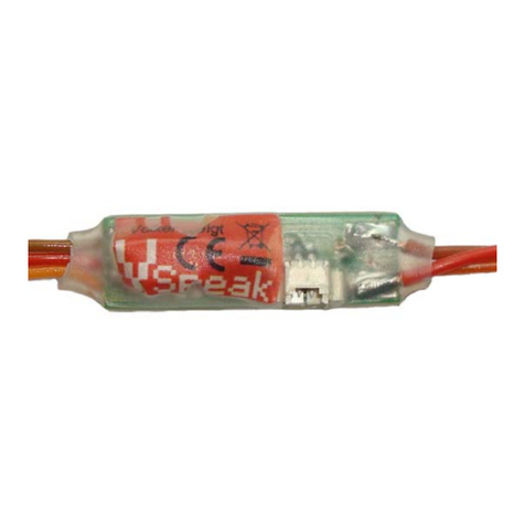
The VSpeak ECU Converter provides the data of the PBS turbine on the telemetry system of
your remote control system.
In the systems Jeti Duplex and Graupner HoTT the VSpeak ECU converter replaces the PBS
EDT (Terminal) completely, that means not only the indicators of the EDT are displayed on the
transmitter - also all entries can be made conveniently via the transmitter.
To avoid unwanted electrical effects between the Turbine and RC-system the VSpeak
ECU Converter is galvanically isolated.
The VSpeak ECU Converter can be software-updated by the user.
6 mm
22 mm
60 mm

ECU converter PBS Version: 1.3 www.VSpeak-modell.de Page 2/43
Content Page
1Hardware................................................................................................................................ 4
2Telemetry................................................................................................................................ 5
2.0 Selection of the telemetry system.......................................................................................... 5
2.1 Jeti Duplex EX ....................................................................................................................... 6
2.1.1 EX-data DC/DS-radio...............................................................................................................6
2.1.2 Jetibox.......................................................................................................................................6
2.1.2.1 Key assignment ...................................................................................................................................... 6
2.1.2.2 Turbinestatus –numerical Values.......................................................................................................... 7
2.1.2.3 Alarms / Parameterization ..................................................................................................................... 8
2.1.2.4 Expandermenu ..................................................................................................................................... 10
2.1.3 Profibox - autonomous telemetry system for PBS turbine......................................................10
2.2 Multiplex MLink (MSB)...................................................................................................... 11
2.2.1 Address-Assignment................................................................................................................11
2.2.2 Turbine-Status.........................................................................................................................11
2.2.3 Setup........................................................................................................................................12
2.2.3.1 MSB ADDRESS.................................................................................................................................... 13
2.2.3.2 FUEL-CONSUMPT. ............................................................................................................................ 13
2.2.3.3 ALARM................................................................................................................................................. 13
2.3 Graupner HoTT................................................................................................................... 14
2.3.1 Sensortype...............................................................................................................................14
2.3.2 Textdisplay..............................................................................................................................14
2.3.2.1 Key assignment .................................................................................................................................... 15
2.3.3 Data-Display/Speech ..............................................................................................................15
2.3.3.1 GAM - General Air Modul................................................................................................................... 15
2.3.3.2 ESC - Electronic Speed Control........................................................................................................... 16
2.3.3.3 VAR - Vario.......................................................................................................................................... 16
2.3.4 Parameterization ....................................................................................................................17
2.3.4.1 Alarms.................................................................................................................................................. 18
2.3.4.2 FUEL consumption / Sensor ID ........................................................................................................... 19
2.4 Futaba S.BUS2..................................................................................................................... 20
2.4.1 Registration at the transmitter................................................................................................20
2.4.2 Mapping Sensor –Turbine Values..........................................................................................20
2.4.3 Turbinestatus –numerical "Current"-Values.........................................................................21
2.4.4 Telemetry Box .........................................................................................................................21
2.4.5 Setup........................................................................................................................................22
2.4.5.1 SENSOR ADDRESS............................................................................................................................. 23
2.4.5.2 FUEL-CONSUMPT. ............................................................................................................................ 23
2.4.5.3 ALARM................................................................................................................................................. 23
2.4.5.4 SYSTEM ............................................................................................................................................... 24
2.5 Futaba S.BUS2 V10............................................................................................................. 25
2.5.1 Registration at the transmitter................................................................................................25
2.5.2 Mapping JetCat V10 –ECU Values .......................................................................................26
2.5.3 Turbinestatus –numerical "Current"-Values.........................................................................26
2.5.4 Setup........................................................................................................................................27
2.5.4.1 SENSOR ADDRESS............................................................................................................................. 28
2.5.4.2 FUEL-CONSUMPT. ............................................................................................................................ 28
2.5.4.3 ALARM................................................................................................................................................. 28
2.5.4.4 SYSTEM ............................................................................................................................................... 29
2.6 FrSKY S.Port....................................................................................................................... 30
2.6.1 LUA script for Taranis............................................................................................................30
2.6.2 LUA script for Horus (openTX)..............................................................................................30

ECU converter PBS Version: 1.3 www.VSpeak-modell.de Page 3/43
2.6.3 Turbinenstatus –numerical „Temperature“-Values..............................................................31
2.6.4 S.Port ID.................................................................................................................................31
2.6.5 Setup........................................................................................................................................32
2.6.5.1 FUEL-CONSUMPT. ............................................................................................................................ 32
2.6.5.2 SYSTEM ............................................................................................................................................... 32
2.7 JR PROPO............................................................................................................................ 33
2.7.1 Turbinestatus –numerical "Current"-Values.........................................................................34
2.7.2 Setup........................................................................................................................................35
2.7.2.1 FUEL-CONSUMPT. ............................................................................................................................ 35
2.7.2.2 SYSTEM ............................................................................................................................................... 35
2.8 PowerBox P²Bus................................................................................................................... 36
2.8.1 setup........................................................................................................................................36
2.8.1.1 FUEL.................................................................................................................................................... 36
2.8.1.2 PRIORITY ............................................................................................................................................ 37
2.8.1.3 SYSTEM ............................................................................................................................................... 37
2.9 Spektrum (X-Bus)................................................................................................................ 38
2.9.1 Telemetry display....................................................................................................................38
2.9.2 Turbine-Status.........................................................................................................................38
2.9.3 Setup........................................................................................................................................39
2.9.3.1 TELEMETRY SET................................................................................................................................ 39
2.9.3.2 FUEL-CONSUMPT. ............................................................................................................................ 40
3Update................................................................................................................................... 41
4Accessories............................................................................................................................ 41
5Technical data...................................................................................................................... 41
6Instructions for disposal...................................................................................................... 41
7EG Declaration of Conformity ........................................................................................... 42
8Version history..................................................................................................................... 42
9Contact.................................................................................................................................. 43

ECU converter PBS Version: 1.3 www.VSpeak-modell.de Page 4/43
1Hardware
The Micro SD card slot is used for updates.
The blue LED is blinking every second to signal the normal function of the ECU Converter.
The Data LED green / red indicates the data exchange with the turbine or the EDT.
Connection: 1. Turbine
The black JR servo plug is connected to the "EDT" marked
connector of the turbine.
Data exchange between turbine and VSpeak converter is signaled by
the 2-color Data LED green .
2. EDT (Engine Data Terminal)
On the black JR servo female plug the EDT - terminal can be
connected. The power supply of EDT is supplied by the turbine.
The attached EDT will be displayed by the 2-color Data LED red .
The EDT can be connected and disconnected at any time.
3. Telemetry data
Jeti / MSB / HoTT / Futaba:
JR servo plug blue
The blue JR servo plug is connected to the telemetry port
of your receiver.
O R, Spektrum-Version:
X Bus plug
The X Bus plug of the ECU Converter is connected to
the X-BUS connector of TM1000 or Spektrum receiver
with X-BUS connector.
The attachment of the VSpeak ECU converter in the model can be done with velcro tape, double
sided tape or cable ties.
Micro SD card slot
blue LED
Data LED green / red
JR servo plug black
JR servo male plug black

ECU converter PBS Version: 1.3 www.VSpeak-modell.de Page 5/43
2Telemetry
The voltage for the VSpeak ECU Converter is supplied by the receiver. Valid turbine data is
only displayed when the turbine is switched on.
If the EDT is connected, data will be transmitted between EDT and VSpeak ECU Converter.
Thus, the turbine data is not updated with connected EDT. The Data LED indicates the currently
active data connection.
The telemetry of the ECU Converter can be switched between the systems Jeti Duplex EX,
HoTT, Multiplex and Futaba, see section 2.0.
The ECU Converter for spectrum comes with the special XBus connector, so no switching for
another telemetry system is possible here. By connecting the EDT a version display is shown
by the ECU converter, followed by the System display after a short initialization:
2.0 Selection of the telemetry system
The telemetry system can be adjusted by the EDT.
After the EDT is connected (turbine and receiver are turned on), the version display of ECU
converter is shown, followed by the display of the currently selected remote control system
after a brief EDT initialization.
With the UP / DOWN buttons of the EDT the desired remote control system can be changed
and optionally other settings are made with the SET button.
The settings are saved.
For safety, the telemetry output of the ECU converter is deactivated every time the system
changes. After reboot data is available at the telemetry output in the format of the selected
remote control system.
PBS Ve l ka B i tes
> PowerBox P2 <
section 2.2.3
section 2.4.5
PBS Ve l ka B i tes
> > Futaba < <
PBS Ve l ka B i tes
> Jet i Dup l ex EX <
PBS Ve l ka B i tes
> Mul t i pl ex MSB <
PBS Ve l ka B i tes
> Graupner Hott<
section 2.5.4
PBS Ve l ka B i tes
> > Futaba V10 < <
section 2.6.3
PBS Ve l ka B i tes
> > FrSKY < <
section 2.7.2
PBS Ve l ka B i tes
> > JR PROPO < <
VSpeak ECU-Conv .
--PBS VB-- V1 . 3
section 2.9.3
PBS Ve l ka B i tes
> > Spektrum < <
VSpeak ECU-Conv .
--PBS VB-- V1 . 3

ECU converter PBS Version: 1.3 www.VSpeak-modell.de Page 6/43
2.1 Jeti Duplex EX
2.1.1 EX-data DC/DS-radio
The EX-Protocol is partially backwards compatible. On older non-EX devices you get only
Jetibox functions. On EX devices like the DC/DS radios and the Jeti "Profibox" you get
additional data.
(VSECU … VSpeak ECU Converter):
The EX - data is not updated if the ECU
converter is connected to the EDT , or in the
Jetibox if PBS turbine SETUP is called.
In the "top" turbine display , so the turbine status indicator , the key assignment is as follows:
left button: Return to Expandermenu (if ECU Converter is used together with other
sensors via an expander)
right button: pressed long -> Setup turbine
down button: Setup ECU converter (see section 2.1.2.3)
up button: Selection of display: FP . . . V Ub . . . V . . . kmh
2.1.2 Jetibox
On the Jetibox all data of the PBS turbine normally displayed on the TERMINAL are shown
(except characters that cannot be displayed on Jeti Systems).
Furthermore you can use the Jeti-keys to edit all values available on the EDT. Please refer to
the PBS turbine's manual.
2.1.2.1 Key assignment
PBS
EDT
UP
UP
DOWN
SET
resp.
ESC
UP
SET
resp.
ESC
DOWN
UP
PBS EDT

ECU converter PBS Version: 1.3 www.VSpeak-modell.de Page 7/43
2.1.2.2 Turbinestatus –numerical Values
The turbines status messages are also displayed numerical values. The assignment is given in
the following table.
As "Error = -30" all others errors, not listed in
the table are interpreted messages, which are
errors that can lead to a shutdown of the turbine
or not even allow it to start.
These status values can be used in Jeti radios, e.g. in logical links, or in LUA-supported radios
for LUA scripts.
PBS
Turbine Status
Status
STOP
0
Th : I d l e
10
Th : -Re l
20
TEST
25
START
30
F IRE
40
I DLE
70
LOCK
- 1
COOL
- 10
Error
- 30

ECU converter PBS Version: 1.3 www.VSpeak-modell.de Page 8/43
2.1.2.3 Alarms / Parameterization
From the ECU data display, the parameter display can be accessed by pressing the
Down button.
With the Up button the parameter display will left (..to ECU data display).
Within the parameter display you can scroll with the Right button - or - Left button
between the parameter groups "Alarm", "Alarmcode", "F-Flow/Pump", "Fueltank Size",
"ECU-EX-Name" and "Taxi Tank".
When the desired parameter group is selected, the parameter can be changed by using
Down and Up button.
Value changes are made with the Right button –or- Left button.
Example of parameter selection and parameterization:
Down button
Right button
Down button
Right button (multiple times)
Up button
Up button
Parameter-
group
Parameter
Value range
Step size
Set- Value
(Default)
Alarm
F-RES
100 . . . 2500 ml
10 ml
800 ml
BATT
5.0 . . . 12.0 V
0.1 V
5.0 V
EGT
400 . . . 995 °C
5 °C
700 °C
RPM
20.000 . . . 99.900 rpm
100 rpm
OFF
Alarmcode
FUEL
A, B, C, . . . , X, Y, Z
C
BATT
U
EGT
T
RPM
L
F-Flow /
Pump
@ 1,5 V
10 . . . 600 ml/min
1 ml/min
112 ml/min
@ 3,0 V
10 . . . 2000 ml/min
1 ml/min
272 ml/min
Fueltank
Size
200 . . . 20.000 ml
100 ml
3.000 ml
Jeti-Sensor
EX Name
VSECU, L-ECU, R-ECU, 1LECU, 2RECU
VSECU
Taxi Tank
OFF, ON
OFF
Taxi Tank

ECU converter PBS Version: 1.3 www.VSpeak-modell.de Page 9/43
Alarms
Irrespective of the possibility to program alarm thresholds for the "EX" values in Jeti
transmitters the VSpeak ECU Converter has the ability to set alarms (by using alarm codes) that
are turbine status depending. These alarms can also be emitted by the Profibox as voice
messages.
F-RES
The alarm Fuel Reserve is signaled if the fueltank size is exceeded less fuel consumption set
at F - RES.
The alarm stops as soon as a status message is transmitted, i.e.: LOCK, COOL or ERROR.
In addition, the alarm can also be acknowledged by sending a throttle value below 10% for
a moment.
F-RES = OFF -> Alarm is disabled
BATT
The alarm BATT is signaled if the turbine battery voltage falls below the value set at BATT.
BATT = 5.0V -> should never occur , alarm is thus disabled
EGT
The alarm EGT is signaled if the temperature exceeds the value set at EGT.
EGT = 995°C -> should never occur , alarm is thus disabled
RPM
The alarm RPM is signaled if the rotation speed falls below the minimum rotation speed.
Speed monitoring is started when the speed exceeds the minimum speed and ends
at PUMP = 0,0V
RPM = OFF -> Alarm is disabled
The alarms described above are max. 3 times
repeated.
ERROR = "turbine flameout"
"Status = -30" are all other errors not listed in the
table which can lead to a shutdown of the turbine or
not even allow it to start.
If an alarm Status < -1 is programmed in the
transmitter a "turbine flameout" can safely be
signaled.
PBS
Turbine Status
Jeti
Status
STOP
0
Th : I d l e
10
Th : -Re l
20
TEST
25
START
30
F IRE
40
I DLE
70
LOCK
-1
COOL
- 10
Error
- 30

ECU converter PBS Version: 1.3 www.VSpeak-modell.de Page 10/43
FUEL consumption
The VSpeak ECU converter can calculate the current fuel flow (F-FLOW) and the fuel
consumption (FUEL) on the basis of the turbine pump voltage. The required parameters can be
adjusted in "F-flow / Pump".
Tips for determining the fuel flow rate can be found in the appendix of these operating
instructions.
Fueltank size is the capacity of the main tank in ml. The tank size is required for the calculation
of the alarm for the fuel consumption (see above alarms: F RES).
Jeti EX sensor name
In a 2-turbine model 2 VSpeak ECU converter can be used on Jeti Systems via an expander or
CentralBox. The EX names are:
"1LECU" for Left turbine ECU converter on input 1and
"2RECU" for Right turbine ECU converter at the expander input 2.
Taxi Tank
For models where a taxi tank is plugged into the main tank until the model is lifted off, set
"Taxi = ON". If the turbine is "Running", then when THROTTLE = 80% is exceeded for the
second time, the FUEL will "reset", ie the consumed FUEL is only once set to "0" again at this
time.
2.1.2.4 Expandermenu If the VSpeak ECU Converter is connected to an
Expander or Centralbox and the ECU Converter display
is activated with the Right button, the only way back
to the expander menu is pressing Left button in
turbine data display.
2.1.3 Profibox - autonomous telemetry system for PBS turbine
Using a Jeti Profibox incl. RSat receiver and the VSpeak ECU converter the telemetry data
from a PBS turbine can be transferred completely self-sufficient to the pilot. Not only the
settings using the Profibox can be made, as was shown in the previous chapters - all EX-data
and the important alarms are displayed: EGT, fuel consumption, turbine battery voltage . . . are
given as voice messages again.

ECU converter PBS Version: 1.3 www.VSpeak-modell.de Page 11/43
2.2 Multiplex MLink (MSB)
The MSB (Multiplex Sensor Bus) is only uni-directional. You can only see the telemetry data,
but you cannot change parameters of the PBS turbine.
2.2.1 Address-Assignment
The VSpeak ECU Converter at delivery uses following addresses:
PBS
Turbine
address
comment
FUEL Alarm
2
Consumed Fuel in ml
BATT Alarm
3
Battery Voltage in V
EGT Alarm
4
Exhaust Gas Temperature in °C
RPM Alarm
5
Turbine RPM
STATUS
6
Turbine Status
THROTTLE
7
Throttle Value in %
PUMP
8
Pump Voltage in V
FUEL-FLOW
9
Fuel Flow in ml
EGT-PEAK
OFF
max Exhaust Gas Temperature in °C
RPM-PEAK
OFF
max Turbine RPM
PUMP-PEAK
OFF
max Pump Voltage in V
2.2.2 Turbine-Status
To display the turbine status there are various
preset messages in the radio or in the external
display. These do not match the normal
PBS turbine messages 1:1, so the closest match
has been chosen. Please refer to the table on the
left.
As "Error" -OFF- are all other errors not listed
in the table which can lead to a shutdown of the
turbine or not even allow it to start. (turbine
flameout).
PBS
Turbine Status
STOP
Manual
Th : I d l e
Stby/START
Th : -Re l
AccelrDly
TEST
PreHeat1
F IRE
Ignite...
START
acceler.
I DLE
RUN (reg.)
COOL
Cooling
LOCK
-OFF-
Error
-OFF-

ECU converter PBS Version: 1.3 www.VSpeak-modell.de Page 12/43
2.2.3 Setup
For the Multiplex Sensor Bus (MSB) a variety of settings in
VSpeak ECU converter using the PBS EDT (Engine Data
Terminal) can be made.
In the overview the complete menu structure for all possible
range of settings is shown.
The navigation takes place in the usual way with the
UP / DOWN buttons and the SET button
or SET button Long-pressed == ESC
PBS Ve l ka B i tes
> Mu l t i p l ex MSB <
1: MSB ADDRESS
> > >
10: FUEL
2 ?
11: BATT
3 ?
2: FUEL-CONSUMPT .
> > >
20: F-FLOW @ 1 . 5V
112 m l/m i n ?
3: ALARM
> > >
30: FUEL-RESERVE
800 m l ?
31: RPM
20000 rpm ?
21: F-FLOW @ 3 . 0V
272 m l/m i n ?
12: EGT
4 ?
22: FUELTANK SIZE
3000 m l ?
32: BATT
5 . 0 V ?
13: RPM
5 ?
33: EGT
700 C ?
17: FUEL-FLOW
9 ?
18: EGT--PEAK
OFF ?
19: RPM--PEAK
OFF ?
1A: PUMP-PEAK
OFF ?
14: STATUS
6 ?
15: THROTTLE
7 ?
16: PUMP
8 ?
23: TAX I TANK
OFF ?

ECU converter PBS Version: 1.3 www.VSpeak-modell.de Page 13/43
2.2.3.1 MSB ADDRESS
MSB-compliant, the addresses can be arbitrarily set between 0 and 15. Not to show values can
be turned off ("OFF").
An address for double occupancy values within the ECU converter is excluded. If an address
has been set, which was already associated with another value, the current is set to "OFF".
2.2.3.2 FUEL-CONSUMPT.
The VSpeak ECU converter can calculate the current fuel flow (F-FLOW) and the fuel
consumption (FUEL) on the basis of the turbine pump voltage. The required parameters can be
adjusted in this menu.
In points 20 and 21: "FL / 1.5V" the fuel flow in ml/min is associated to the pump voltage of
1.5V. Same at "FL / 3.0V" but to 3.0V.
Tips for determining the fuel flow rate can be found in the appendix of these operating
instructions.
FUELTANK SIZE is the capacity of the main tank in ml. The tank size is required for the
calculation of the alarm for the fuel consumption (see section 2.2.3.3).
23:TAXI TANK
For models where a taxi tank is plugged into the main tank until the model is lifted off, set
"Taxi = ON". If the turbine is "Running", then when THROTTLE = 80% is exceeded for the
second time, the FUEL will "reset", ie the consumed FUEL is only once set to "0" again at
this time.
2.2.3.3 ALARM
30:FUEL-RESERVE
The alarm Fuel Reserve is signaled if the fueltank size is exceeded less fuel consumption set
at F - RES.
The alarm stops as soon as a status message is transmitted, i.e.: LOCK, COOL or ERROR.
In addition, the alarm can also be acknowledged by sending a throttle value below 10% for
a moment.
F-RES = OFF -> Alarm is disabled
31:RPM
The alarm RPM is signaled if the rotation speed falls below the minimum rotation speed.
Speed monitoring is started when the speed exceeds
the minimum speed and ends at PUMP = 0,0V
RPM = OFF -> Alarm is disabled
32:BATT
The alarm BATT is signaled if the turbine battery voltage falls below the value set at BATT.
BATT = 5.0V -> should never occur , alarm is thus disabled
33:EGT
The alarm EGT is signaled if the temperature exceeds the value set at EGT.
EGT = 995°C -> should never occur , alarm is thus disabled

ECU converter PBS Version: 1.3 www.VSpeak-modell.de Page 14/43
2.3 Graupner HoTT
Using the HoTT System there are 2 ways to transmit telemetry data, on the one hand as "text"
and on the other hand only the pure values.
Using text mode it is possible to establish a bi-directional data transfer, meaning you can use
the keys of the radio or the Smartbox in order to change/enter values in the sensor. Using speech
output is not possible in this mode.
In data-mode the values are only transmitted in a fixed format in one direction. The format is
defined by the sensor type. In this mode it is possible to have speech output for the sensor
values.
2.3.1 Sensortype
The VSpeak ECU Converter for HoTT is a GAM (General Air Module) or a ESC sensor
(Electronic Speed Controll). Please select this sensor-type on your radio or Smartbox.
2.3.2 Textdisplay
Using the text-display you can see the current turbine data and you can also change parameters
of the PBS turbine.
Change to input
Alarms / parameters
of the ECU converter
(see section 2.3.4)
Only on this screen you can change
values of the PBS turbine
(see section Key assignment).
With the HoTT-keys it is possible to emulate the full functionality of the EDT. For further
details on the specific values please consult the manual of the PBS turbine.
INC +
DEC
SET
ESC
ENTER
INC +
DEC
SET
or

ECU converter PBS Version: 1.3 www.VSpeak-modell.de Page 15/43
2.3.2.1 Key assignment
PBS
EDT
ESC
DOWN
UP
SET
2.3.3 Data-Display/Speech
2.3.3.1 GAM - General Air Modul
Since the GAM can only display temperatures up to 235°C, the temperature is divided by 10.
If you see a value of 60°C on the display, you have a "real" temperature of 600 - 609°C.
The pump voltage is displayed as "Cell Voltage 1", ranging from 0V up to 5.10V (accuracy
100mV).
The fuel consumption is indicated on the one hand in ml and in the other as "decreasing" tank
level in percentage (see picture above). To calculate the percentage of tank volume value F-
SIZE is 100% fully set when turned on.
If an Airspeed Sensor is connected to the ECU, the speed is displayed in in kmh and also m/s.
ESC
DEC
INC
ENTER
AUF
MX-12
MX-16
MC-16
MC-20
MC-32
SET
SET
ESC
AB
At HoTT system a separate
control of the SET and ESC
function occurs differing
from the EDT:
SET:
SmartBox ENTER button or
HoTT transmitter right
button
ESC:
short actuation of
SmartBox ESC key or the
HoTT transmitter left button
FUEL in %
PUMP
FUEL
BATT
EGT
BATT (max)
RPM
EGT (max)
Turbine runs

ECU converter PBS Version: 1.3 www.VSpeak-modell.de Page 16/43
2.3.3.2 ESC - Electronic Speed Control
The ESC temperature display is limited to 235 ° C, so the turbine jet temperature is shown
divided by 10, or the other way around: 60 ° C in the display corresponds to 600 ... 609 °C.
The fuel consumption is displayed on the display as capacity value, ie, 1560mAh are 1560ml.
On the other hand, the percentage tank level is displayed as the current, ie, 48A correspond to
48% tank level. The tank level is thus easy to read via the associated bar display. To calculate
the percentage of tank volume, F-SIZE is set to 100% after power on. For example a 1560ml
fuel consumption and F-SIZE = 3000ml correspond to a current tank ratio of 48%.
2.3.3.3 VAR - Vario
The HoTT Vario offers the possibility to display texts, in the example two lines with an MC20.
However, since the displayable number of 21 characters is less than in the two-line display of
the PBS EDT (2x 16 characters), the display was "compressed" as follows:
The tank level is converted in a percentage and displayed as altitude, e.g. 48m corresponds to
48% tank level (can be used for the speech output). The 100% value is set at startup. The value
in ml transferred during the powerup of the ECU is used as 100% value for calculation.
Furthermore, the alarms according to section 2.3.4.1 are also effective here.
EGT
Status / Throttle
PUMP
RPM (x1000)
FUEL in %
BATT (max)
FUEL
BATT
EGT
RPM
RPM (max)
EGT (max)

ECU converter PBS Version: 1.3 www.VSpeak-modell.de Page 17/43
2.3.4 Parameterization The change of sides takes place
with Enter and ESC button of the
SmartBox or with the appropriate
buttons on the HoTT transmitter.
The parameter is selected
with the INC- and DEC-
buttons of the SmartBox
(or the buttons oft he Hott
transmitter) ">".
DEC
INC
ESC
ENTER
With or the value of the
selected parameter is enabled for change
(inverted).
With the value can be increased,
With it can be reduced.
Stored is after or
INC+DEC
SET
INC
DEC
SET
INC+DEC

ECU converter PBS Version: 1.3 www.VSpeak-modell.de Page 18/43
2.3.4.1 Alarms
Settings
Value range
Step size
Signal tone
100 . . . 2500 ml
10 ml
U
5.0 . . . 12.0 V
0.1 V
P
400 . . . 995 °C
5 °C
H
20.0 . . . 99.9 x 1000rpm
100 rpm
T
-10 / -1 / OFF
E
Upon delivery, the warning thresholds are set as shown in the picture.
F-RES
The alarm Fuel Reserve is signaled if the fueltank size is exceeded less fuel consumption set
at F - RES.
The alarm stops as soon as a status message is transmitted, i.e.: LOCK, COOL or ERROR.
In addition, the alarm can also be acknowledged by sending a throttle value below 10% for
a moment.
F-RES = OFF -> Alarm is disabled
BATT
The alarm BATT is signaled if the turbine battery voltage falls below the value set at BATT.
BATT = 5.0V -> should never occur , alarm is thus disabled
EGT
The alarm EGT is signaled if the temperature exceeds the value set at EGT.
EGT = 995°C -> should never occur , alarm is thus disabled
RPM
The alarm RPM is signaled if the rotation speed falls below the minimum rotation speed.
Speed monitoring is started when the speed exceeds the minimum speed and ends
at PUMP = 0,0V
RPM = OFF -> Alarm is disabled
ERROR = "turbine flameout"
"Error -10" are all other errors not listed in the table
which can lead to a shutdown of the turbine or not
even allow it to start.
If an alarm ERROR = -10 is programmed in the
transmitter a "turbine flameout " can safely be
signaled.
PBS
Turbine Status
ERROR
STOP
0
Th : I d l e
0
Th : -Re l
0
TEST
0
F IRE
0
START
0
I DLE
0
COOL
0
LOCK
-1
Error
- 10

ECU converter PBS Version: 1.3 www.VSpeak-modell.de Page 19/43
2.3.4.2 FUEL consumption / Sensor ID
The VSpeak ECU converter can calculate the current fuel flow (F-FLOW) and the fuel
consumption (FUEL) on the basis of the turbine pump voltage. The required parameters can be
adjusted in "Setup (FUEL)".
At "FL / 1.5V" the fuel flow in ml/min is associated to the pump voltage of 1.5V. Same at
"FL / 3.0V" but to 3.0V
Tips for determining the fuel flow rate can be found in the appendix of these manual.
F-SIZE is the capacity of the main tank in ml. The tank size is required for the calculation of
the alarm for the fuel consumption (see above alarms: F RES).
Settings
Value range
Step size
10 . . . 600 ml
1 ml
10 . . . 2000 ml
1 ml
200 . . . 20.000ml
100 ml
OFF, ON
GAM / ESC / VAL
Upon delivery, the warning thresholds are set as shown in the picture.
For models where a taxi tank is plugged into the main tank until the model is lifted off, set
"Taxi = ON". If the turbine is "Running", then when THROTTLE = 80% is exceeded for the
second time, the FUEL will "reset", ie the consumed FUEL is only once set to "0" again at this
time.
In sensor the sensor type can be GAM or ESC . The change of the sensor type will only take
effect after restarting the ECU converter.

ECU converter PBS Version: 1.3 www.VSpeak-modell.de Page 20/43
2.4 Futaba S.BUS2
The S.BUS2 is only unidirectional, that means the sensor data is transmitted from the receiver.
It will not transmit data from the transmitter to the sensor. A parameterization of the PBS turbine
is not possible with this system.
The VSpeak ECU converter is fully compatible with S.BUS2. Registration and connection are
established as with any other S.BUS2 sensor
Caution:
We generally recommend a strict separation between sensor values and servo data. Although
the S: BUS 2 can transmit servo data, the S.BUS2 should exclusively be used for the
transmission of sensor data and only the S.BUS1 should be used for the servos. In this way, the
servo data are excluded from influencing on failure of a sensor.
2.4.1 Registration at the transmitter
The VSpeak ECU converter must be registered on the transmitter like any S.BUS2 sensor. For
this purpose, the JR servo plug blue of the VSpeak ECU converter must be connected with a
V cable and a receiver battery to the "S.I/F" jack of the transmitter.
Now the registration of VSpeak ECU converter can be done - please look up into the
instructions for the transmitter.
Since the VSpeak ECU converter displays its data using a total of 5 sensors, the registry has
also be done 5 times. Of course, the starting slots can also be set manually.
2.4.2 Mapping Sensor –Turbine Values
No
Sensor name
Slots
Start
(default)
original
Sensor value
Turbine value
1
CUR-F1678
3
24
CURRENT
Turbine-Status (s. section 2.4.3)
VOLTAGE
BATT in V
CAPACITY
FUEL in ml
2
SBS-01RM/O
1
27
R.P.M
RPM in rpm
3
SBS-01V
2
28
BATTERY
PUMP in V
EXT-VOLT
THROTTLE in %
4
SBS-01T
1
30
TEMP
F-FLOW in ml
5
SBS-01T
1
31
TEMP
EGT in °C
E.g. using a T18MZ transmitter: The sensors are displayed after registration as seen below:
Table of contents
Other VSpeak Control Unit manuals