closomat Palma Vita Operation manual

Closomat Palma Vita
installation &
user guide.

2
Technical data
Shutdown procedure
•For normal isolation, the Closomat toilet can be
turned off using the integrated switch. To carry out
any servicing, the unit MUST be isolated at the
mains feed.
Bathroom/shower room
installations
• The Closomat toilet must not be in direct line
with the shower spray. Some form of partition
between shower and the Closomat toilet is
advisable to prevent any water spraying directly
onto the equipment.
• A shower should not be used in conjunction with
the Closomat toilet i.e. under no circumstances
must a user shower whilst seated on the
Closomat toilet.
Water services (WRAS approved)
•It is essential that the entering water
is cold.
•We would recommend water supply isolated via
isolation valve.
•Water supply can be from storage vessel or mains
(‘Grey Water’ MUST NOT BE USED).
•Boiler Capacity: 1.7 litres.
•Water rate: min. 8 l/min.
max. 0.8 MPa (8 bar)
•Cistern capacity: 6 litres.
Overflow
•The Closomat toilet has an internal overow
which discharges into the W.C. pan through the
ush valve.
Soil connection
•Relevant soil connector to be sourced by installer.
•Soil connections suitable for Closomat toilet;
S-Trap (vertical fall) wall to centre of pipe from
70mm-230mm max. P-Trap (horizontal) oor to
centre of pipe 200mm max.
•The Closomat toilet is suitable for all turned trap
outlets, through purpose made removable side
covers on lower level.
The Closomat toilet MUST
be installed by a competent or
qualied person.
Explanation of symbols
•Safety instructions in this manual are identied by
symbols. The safety instructions are introduced
by signal words, which express the extent of the
hazard/risk.
•In order to prevent accidents, personal injury,
property damage and guarantee maximum user
safety, follow the safety instructions without fail
and exercise caution.
Description of equipment
•The Closomat toilet is an electrically operated
shower (wash and dry) toilet designed to provide
the operator/user with a hygienic solution to toileting.
Start-up procedure
•To enable a warm washing cycle operation
the Closomat toilet must be switched on.
Each Closomat toilet has its own isolation switch.
To switch the unit on, locate the switch on the
right hand side of the unit at the base of the
cistern cover, through a Perspex screen.
•Once switched on, the water will reach core
temperature within 5 minutes. It is advised that to
maintain the core temperature in readiness for
use, the unit be left switched on at all times.
Electrical services
•To avoid the risk of electric shock, this equipment
MUST only be connected to a supply mains with
protective earthing by a competent or qualied
person.
Mains isolation
•All electrical appliances must be installed in
accordance to the relevant regulations associated
with the country it is within. To conduct any form
of repairs or servicing it is recommended that
a mains isolation device be located in the vicinity
of the unit.
•220-240V single phase AC supply is required,
(loading 4.5A-4.9A, maximum power 1300watts).
The Closomat toilet is supplied with a 3 corecable
attached and MUST NOT be removed or replaced.
A 10A fused spur is required for isolation.
•Spur outlet to be located in accordance with
current I.E.E. Regulations (Current Edition).
•No modication of this unit is allowed other than
by the manufacturer.
•Closomat has IPX4 rating.
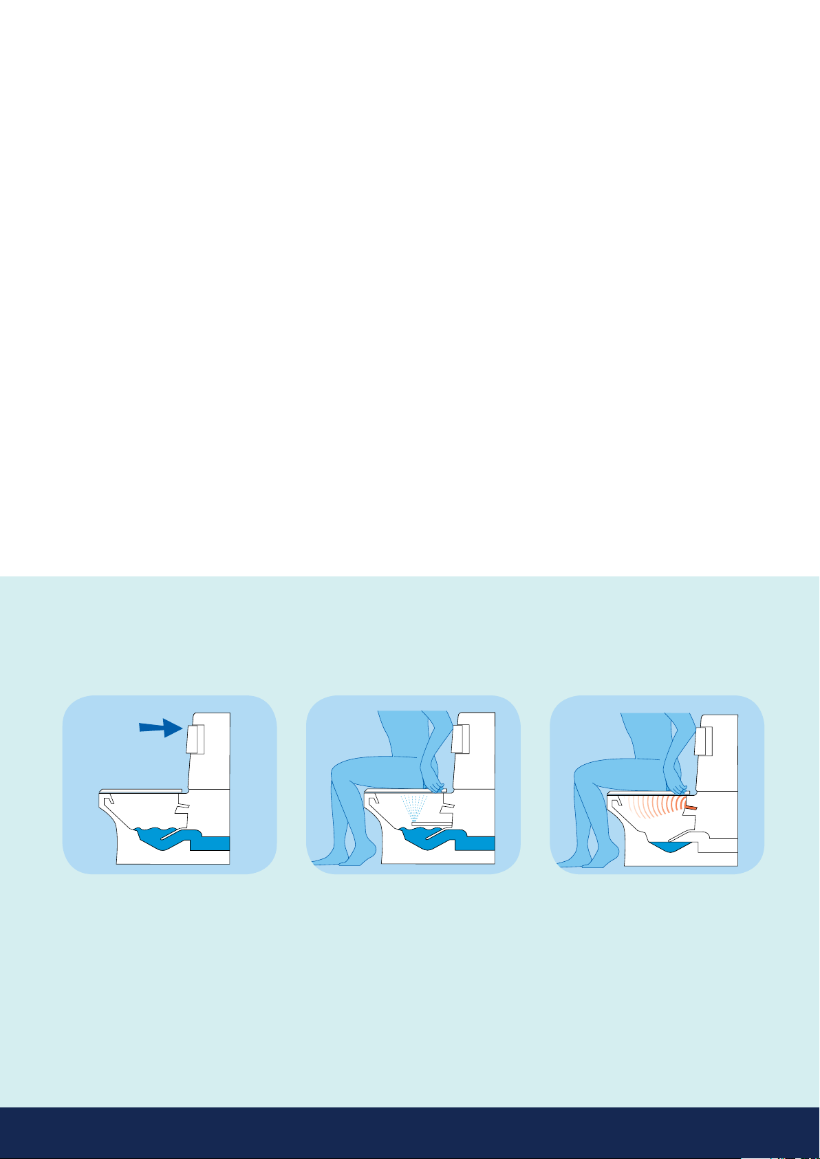
Flushing
Press either elbow pad whilst standing
for conventional ush.
Washing
Press elbow pad whilst seated and hold
down for approximately 10-15 seconds,
ushing and warm water washing will
then take place.
Drying
Warm air drying automatically follows
when elbow pad is released.
Further notes
• No permanent hand rails or other obstructions
should be tted across the front or top of the unit.
The outer casing has to be pulled upwards and
forward to remove for servicing purposes.
• Unit not rated for altitude. 2000m is the
maximum.
• This application requires an earth connection.
• Environmental conditions – operating ambient
room temperature maximum = 40°C.
Environmental conditions
The Closomat toilet is rated to IPX4 and can be
installed and operated within a typical shower/toilet
room.
Inll panel
The inll panel specications are printed on page 11.
Classification
Low Voltage Directive EN 60335-2-84.
Cleaning information
•The use of bleach products is not advised due
to the exposed stainless metal parts associated
with the washing device. (tarnishing may occur).
•The Closomat toilet washing device is designed
to self cleanse during and after every use.
Normal cleansing of the bowl and outer covers
is required.
Maintenance and frequency of
serviceable parts
•The Closomat toilet is self-sufcient but it is
recommended that a competent experienced
Service Engineer carry out a safety check and
an annual service of the internal workings,
to extend the Closomat’s life.
Risk associated with the waste of
equipment after service life
•At the stage the unit is not repairable it can
be discarded to any appropriate recyclable
plant. There are no immediate risks to the
environment.
User guide
3

•Safe working load: 190kg/30st
•Overall dimensions: 869mm high x 451mm wide x 730mm deep
Key / Installation guide:
1. Determine unit height as standard or with optional points (P)
2. Locate oor & wall template jig to plan positions (J)
3. Locate waste pipe / soil position (S)
4. Locate cold water supply (W)
5. Locate electrical supply (E)
6. Use oor template jig for xing frame (J)
W
Water services
Supplied with 15mm
Stainless steel braided
outer, EDM inner WRAS
approved exible hose.
(Please refer to page 2,
water services prior to
installation)
Waste details
Pan has a horizontal
spigot standard 100mm
diameter outlet, suitable
for standard pan
connection ttings.
DRear wall fixing
Position 25mm to RH of
the centreline. 810mm
from the oor.
RRear oor xing (2No)
(Standards Installations)
Position on the oor
102mm from the rear wall.
119.5mm to each side of
the centreline.
FFront oor xing (2No)
(When using Support Arms)
Position on the oor 327mm
from the rear wall. 119.5mm
to each side of the
centreline.
S
W
S
E
D
S
F
R
Floor & Wall
Templates
Located in
Document Box
J
J
Electrical services
Supplied with 1000mm long,
three core (live/neutral/earth)
insulated 3183Y-1-white
control ex-cable, rated to
220-240V, 4.5A-4.9A.
(Please refer to page 2,
electrical services prior
to installation)
E
Palma Vita planning data
and service requirements
4
www.closomat.co.u
k
Tel: +44 0800 374 076
PALMA VITA
220-240V, 50Hz
4.5A-49A IPX4
10A
190kg
30st

Installation
7 Unhook the xing adjuster brackets
from the frame.
6Loosen and remove the front screw.
8 Repeat unhooking on opposite side
ensuring cover is free.
5 Gently lift the cistern cover upwards
(small arrow) and then pull it forward
and off (large arrow).
3 Carefully loosen and pull out the
covering cap on the cistern cover.
4 Loosen the screw of the cistern cover
completely, but do not remove it.
IMPORTANT: Please retain all packaging until the installation is complete. Protect all oor
surfaces when handling the Closomat. DO NOT slide the Closomat across the ooring.
Pull away cover once adjuster brackets
are loose.
2 Remove the seat – Open the lid. Press
and hold the seat pivots together with
both thumbs whilst rmly gripping
the outer edges of the seat. Now pull
upwards sharply.
1 To lift the Closomat use the porcelain
ushing edge at the front and the steel
frame at rear, and lift it out of the
bottom of the packing.
➞
➞
➞
9
5
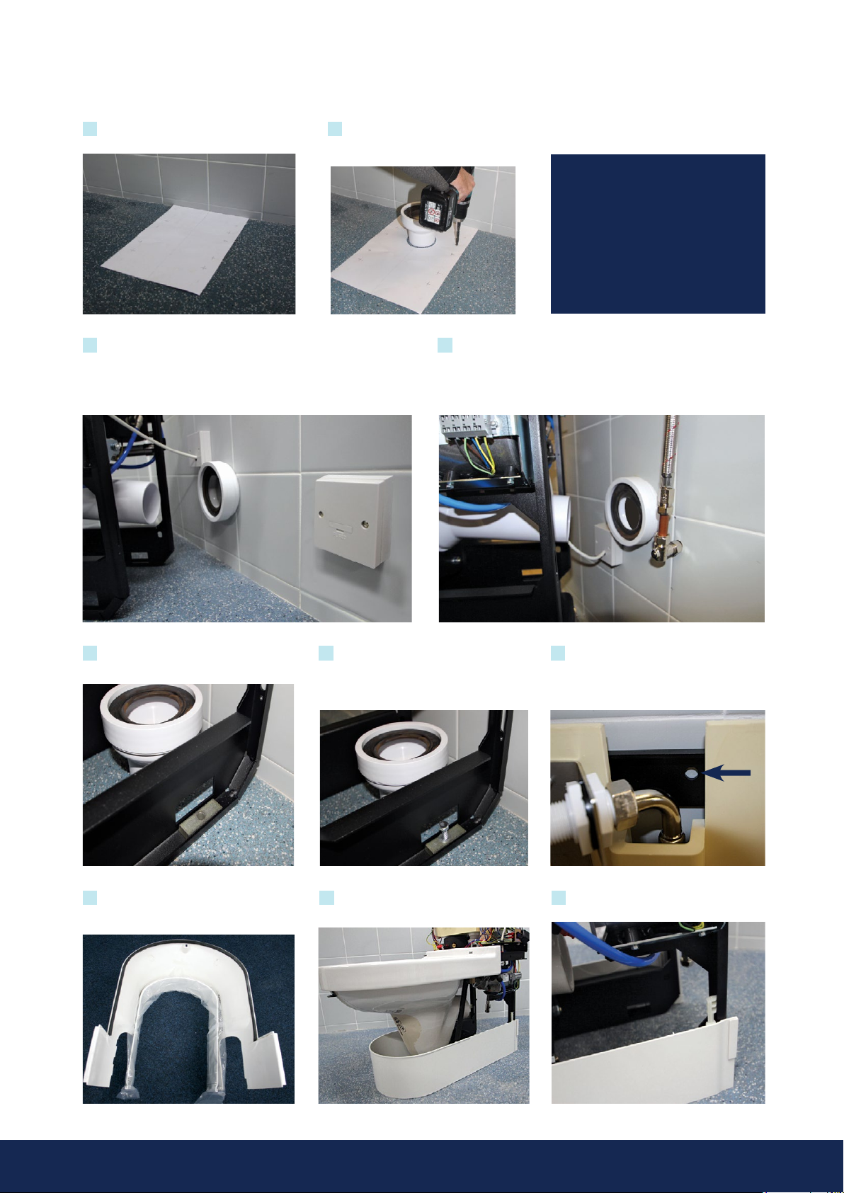
Locate your services, with the electrical isolation positionedoutside
the connes of the toilet covers. Spur outlet to be located in
accordance with current I.E.E. Regulations (Current Edition). Ifsupply
cord is damaged, it must be replaced by the manufacturer, its service
agent or similarly qualied persons in order to avoid a hazard.
13 Cold water connection is via a 15mm connection pipe at the rear
of the unit. We recommend the supply pipe enter the unit through
the oor or through the wall. If side entry is necessary then a
suitable inll panel will be required. The provision of an isolation
valve is always recommended.
14 Position the Closomat and place all four
anchor blocks in place.
15 Secure the Closomat to the oor using
all four xing points, use suitable xing for
the application. Adhesives are not allowed
to be used.
16 Anchor the Closomat to the rear wall.
This xing must be used to ensure stability,
which is imperative when support arms
are tted.
17 Remove the skirt from inside the bowl
cover and insert skirt locators supplied
loose.
18 Place the lower skirt around the base of
the frame.
19 Ensure the skirt locator is engaged to the
frame.
Using the template provided proceed to set
the Closomat’s position in the bathroom.
Drill four holes in the oor to best
suit the intended xings to be used
for the application.
10 11
12
Two templates are provided:
One for oor installations
and
One for wall installations
PLEASE NOTE
6
Installation (cont.)

Test procedure
1 Fill the Closomat with water and switch
on mains electricity. Locate the on/off
switch and click to the on position ‘I’,
the switch will illuminate blue. Check all
joints for leaks.
6 Should the water pressure need
adjusting to suit the user, locate the
pump situated on the right hand side
of the Closomat. Hold down or release
the pump pressure spring slide by either
tightening or untightening the adjacent
holding nut. Clockwise will increase the
pump pressure, whereas anticlockwise
will achieve the opposite.
3 Simultaneously pressing the right hand
seat hull and the operation bar will
activate the warm water wash. Run the
wash for approximately 30 seconds to
ensure water pressure is constant.
4 Should the wash splutter during the
wash cycle described in step 4, the
douche system may need purging to
remove any potential air-lock, generated
during the unit’s transit/installation.
To do this, insert the special tool supplied
hook end into the recess at the bottom
of the douche arm (arrow).
➞
5 Pull out the douche arm using the special
tool, with force against the spring pressure,
until the arm reaches its maximum stop.
Hold the douche arm with a free hand
once fully extended, rotate the tool and
locate the tool into the slot and recess in
the douche arm to hold in this extended
position (arrow). Run wash cycle to purge.
Once wash is constant remove tool and
allow the douche arm to retract.
➞
2 Allow approximately 5 minutes for the water to heat in the boiler. Check the circuit board,
the boiler light will be permanently illuminated red while the water is being heated tothe
operating temperature. As the water temperature approaches the required operating
temperature the light will ash red. If the boiler light does not illuminate, check the safety
stat has not tripped (see inset) by pressing ‘click’ to reset.
➞
Check procedure
1 Ensure electrical supply is connected to unit, and switched on: check that correct fuse is tted.
2 Ensure water supply is turned on and that the inlet valve is allowing water to enter the cistern
and shutting off at correct level. Ensure ow of water is adequate to keep douche supplied.
3 Ensure rear of seat is depressed.
4 Keep elbow pad depressed until water runs cold. Keep seat depressed while hot air is operating.
5 Ensure joints are dry and have not been disturbed during installation.
note
• Foot switch, hand switch or remote switch, if tted, will operate exactly as elbow pads.
• Douche temperature and pressure are preset at factory, and adjustments should only
be carried out by Closomat engineers familiar with the equipment.
note
• The Closomat will not function automatically if the seat switch is not depressed.
• The unit should be switched on electrically at all times when in service.
7

Finishing the installation
3 Replace and tighten the front screw.
1On completion of installation and test
procedure, replace bowl cover.
2 Hook brackets into position. Where
necessary adjust to provide a water tight
seal, adjust the rising block until the seals
are tight against the porcelain.
9 Complete the installation by testing the
Closomat works, by again depressingthe
seat and holding in one of theelbow pads.
8Replace the seat by locating the ‘seat
pivots’ into the seat hulls xed to the
pan – press the seat rmly to secure
its position.
7Push in the seat buffer on the cistern cover.
4Replace cistern cover. Ensuring the clips
on the lower rear edges engage inside
the bowl cover and the on/off switch is
displayed in the right hand side window.
5Correct tted position of cistern cover clips
– shown from rear of unit.
6Replace the screw on the cistern cover and
carefully tighten.
Please advise us of installation address in order that we can
arrange the commission and activate the 12-month guarantee.
8

Side entry pipes
Installation on a plinth
1 With a sharp implement, remove the side
panel screw covers. 2 Remove the screw and set aside. 3 Remove the side panel.
4 Install the side entry pipe scribing the side panel to suit each location,
ret the side panel and screw covers on completion.
1 Using the template provided, locate,
mark and drill four holes for the plinth in
the oor to best suit the intended xings
to be used for the application.
2 Secure the plinth to the oor using all four
xing points, use suitable xing for the
application, prior to installing the Closomat.
3 Locate the Closomat over the plinth.
4 Using ALL four blocks anchor the Closomat to
the plinth.
9

Palma integrated fold-down support
arms installation
Armrest
Left Hand
Stainless
Pivot Bearing
Pivot Block
End Cap
Pivot Block
Nylon
Washer
50mm Dia. Belville
Washer
Pivot Block
Washer
Inserted on to
Pivot Block
Support
arm seal
HOLE CUTTING
POSITION FOR
OUTER COVER
IS MEASURED
TO CENTRE OF
ARM BRACKET
ON FRAME
M20 Bolt
Important
Bolt must not
rotate when the
armrest is
moved.
Important
Ensure Belville Washer is
assembled correctly with the dome towards the bolt head
Hole
diameter
76mm
minimum
78mm
maximum
Measure 367mm from
rear of unit to centre of
arm xing point
Measure from
upper side of porcelain
pan to centre of arm
xing point approx.
207mm – 210mm
How to drill holes in the cover if
armrests are tted
PALMA FITTED WITH FOLD DOWN SUPPORT ARMS, MUST USE ALL FOUR FIXINGS ALONG WITH THE REAR WALL FIXING
(SEE PAGE 6 FOR DETAILS). FLOOR AND WALL FIXINGS INTEGRITY ARE ESSENTIAL FOR UNIT STABILITY.
IMPORTANT NOTE:
10

Palma integrated fold-down support
arms technical data
Inll panel
The inll panel has been designed to aid installation where
pipe-work inhibits the Closomat toilet from being located
against the wall.
The inll panel is available in thickness sizes 25mm, 50mm
and 75mm. The inll panel is 100mm taller than the Closomat
toilet. It must be cut from the bottom to suit the nished
toilet height.
Fixing
positions
373
11

Closomat Limited
Building 1, Brooklands Place,
Brooklands Road,
Sale, Cheshire, M33 3SD
Freephone: 0800 374 076
Telephone: 0161 969 1199
Fax : 0161 973 2711
General Enquiries: info@closomat.co.uk
Sales Orders/Enquiries: sales@closomat.co.uk
Quotations/Pricing: quotations@closomat.co.uk
closomat.co.uk
British manufacturing
British design and development
British customer support
We reserve the right to make modifications as a result of ongoing adjustments and
further development. This factor, and the varietyof equipment options available, may
result in descriptions not corresponding to the current equipment version in all details.
CLOSOMAT® has been the protected trademark of the world’s first wash and dry (shower)
toilet since 1957.
Table of contents
Other closomat Toilet manuals


Popular Toilet manuals by other brands


American Standard
American Standard CONCEPT Cube TF-2704 installation manual

BIOLAN
BIOLAN ECO Instructions for installation, use and maintenance

Thetford
Thetford C260 Series user manual

KELISS
KELISS T162A Series instruction manual

Silent Venus
Silent Venus SVP600 Installation & maintenance

Kohler
Kohler K-22241K Installation and care guide