CMOSTEK CMT2380F64 User manual
CMT2380F64
www.cmostek. com
Rev 0.3 | 1 / 83
MCU Features
◼A 32-bit general-purpose micro-controller based on the Arm® Cortex®-M0 core,Single cycle hardware
multiply instruction
◼Up to 64 KByte on-chip Flash
- supports encrypted storage and hardware ECC verification
- Endurance more than 100,000 cycles, 10 years of data retention
◼8 KByte on-chip SRAM,supports hardware parity
◼Programming method:
-SWD online debugging interface
-UART Bootloader
◼23 / 29 general IO (4 with SPI multiplexing in RF part)
◼Low-power management:
-Stop mode: RTC Runs, maximum 8 KByte SRAM retention, CPU register retention, all IO retention
-Power Down mode (PD): supports 3 IO wakeup
◼Clock:Up to 48 MHz
-HSE :4 MHz~20 MHz,external high-speed crystal
-LSE :32.768 KHz,external low-speed crystal
-HSI:Internal high-speed RC OSC 8 MHz
-LSI:Internal low-speed RC OSC 30 kHz
-Built-in high-speed PLL
-One channel clock output, which can be configured as configurable system clock, HSE, HSI or PLL
post-divided output
◼Reset
- Supports power-on/power-down/external pin reset
- Supports programmable low voltage detection and reset
- Supports watchdog reset
◼Communication Interface
- 3xUART interface, with a maximum rate of 3 Mbps, of which 2 USART interfaces support 1xISO7816 , 1xIrDA,
LIN,1 of which supports low power consumption (LPUART), the highest communication rate in this mode is
9600bps and stop mode can be awakened.
- 2xSPI, the rate is up to 18 MHz, one of which supports multiplexing with I2S
- 2xI2C, the rate is up to 1 MHz, master-slave mode is configurable, and dual-address response is supported
in slave mode
◼Analog interface
-1x12 bit high-speed ADC, 1 Msps, up to 6 external single-ended input channels
-1xOPAMP, built-in programmable gain amplifier up to 32 times
-1xCOMP, built-in 64-level adjustable comparison benchmark
-1x high speed 5-channel DMA control, source address and destination address can be configured
CMT2380F64
Ultra-low Power Sub-1GHz Wireless Transceiver
SoC

CMT2380F64
www. cmostek.com
Rev 0.3 | 2 / 83
arbitrarily
◼Timer/Counter
- 1xRTC (real-time clock), supports leap year perpetual calendar, alarm event, periodic wake-up, supports
internal and external clock calibration
- 2x16 bit Advanced Timer Counters, supports input capture, complementary output, quadrature encoding input,
4 independent channels, of which 3 channels support 6 complementary PWM outputs
- 1x16 bit General Timer, 4 independent channels, supports input capture/output comparison/PWM output
- 1x16 bit Basic Timer
- 1 x 16 bit Low-Power Timer
- 1 x 24 bit SysTick
- 1x 7 bit Window Watchdog (WWDG)
- 1x12 bit Independent Watchdog (IWDG)
◼Hardware Divider (HDIV) and Square Root(SQRT)
◼Security features
◼Flash storage encryption
◼CRC16/32 calculation
- Supports write protection (WRP), multiple read protection (RDP) levels (L0/L1/L2)
- Supports clock failure monitoring, anti-dismantling monitoring
◼96-bit UID and 128-bit UCID
RF Features
◼Working frequency:127 - 1020 MHz
◼Modulation style: (G)FSK, (G)MSK, OOK
◼Data rate:0.5 - 300 kbps
◼Sensitivity:-121 dBm @ 434 MHz,FSK
◼RX current:8.5 mA@ 434 MHz,FSK
◼TX current:72 mA@ 20 dBm, 434 MHz
◼Maximum configurable FIFO of 64 Byte
Overview
CMT2380F64 integrates a 32-bit ARM Cortex®-M0 core with a super low power consumption RF transceiver. It is a high efficiency
super-low power MCU, applying for wireless application of (G) FSK、(G) MSK and OOK transceiver from 127 to 1020
MHz.CMT2380F64 is an ultra-low power, high performance, OOK (G) FSK RF transceiver suitable for a variety of 140 to 1020 MHz
wireless applications. CMT2380F64 operates from 1.8 V to 3.6 V and supports up to +20 dBm TX power consumption and -121
dBm receiving sensitivity with the corresponding TX current and RX current of 72 mAand 8.5 mA.(MCU power consumption is not
included). CMT2380F64 integrates a wealth of peripherals supports standard UART, I2C and SPI interface, with up to 23 general IO
System Features
◼Working voltage:1.8 –3.6 V
◼Working temperature:-40 –85 ℃
◼Package: QFN40 5x5 / QFN 48 6x6

CMT2380F64
www. cmostek.com
Rev 0.3 | 3 / 83
(CMT2380F64-EQR40)/ 30 general IO(CMT2380F64-EQR48), supports internal high speed /low speed low power consumption
RC oscillator and 32.768 kHz externalcrystal oscillator, supports a variety of packet formats and encodingand decoding methods up
to 64-byte Tx/Rx FIFO, supports featured rich RF GPIO, a variety of low power operation mode and fast startup mechanism, high
precision RSSI, manual fast frequency hopping and 12 bit high speed ADCmulti-channel input,etc. CMT2380F64 has a small QFN
package size of 5mmx5mm/6mmx6mm, which is ideal for small size and power consumption of Internet applications.
Application
Auto metering
Home security and building automation
Wireless sensor nodes and industrial monitoring
ISM band data communication
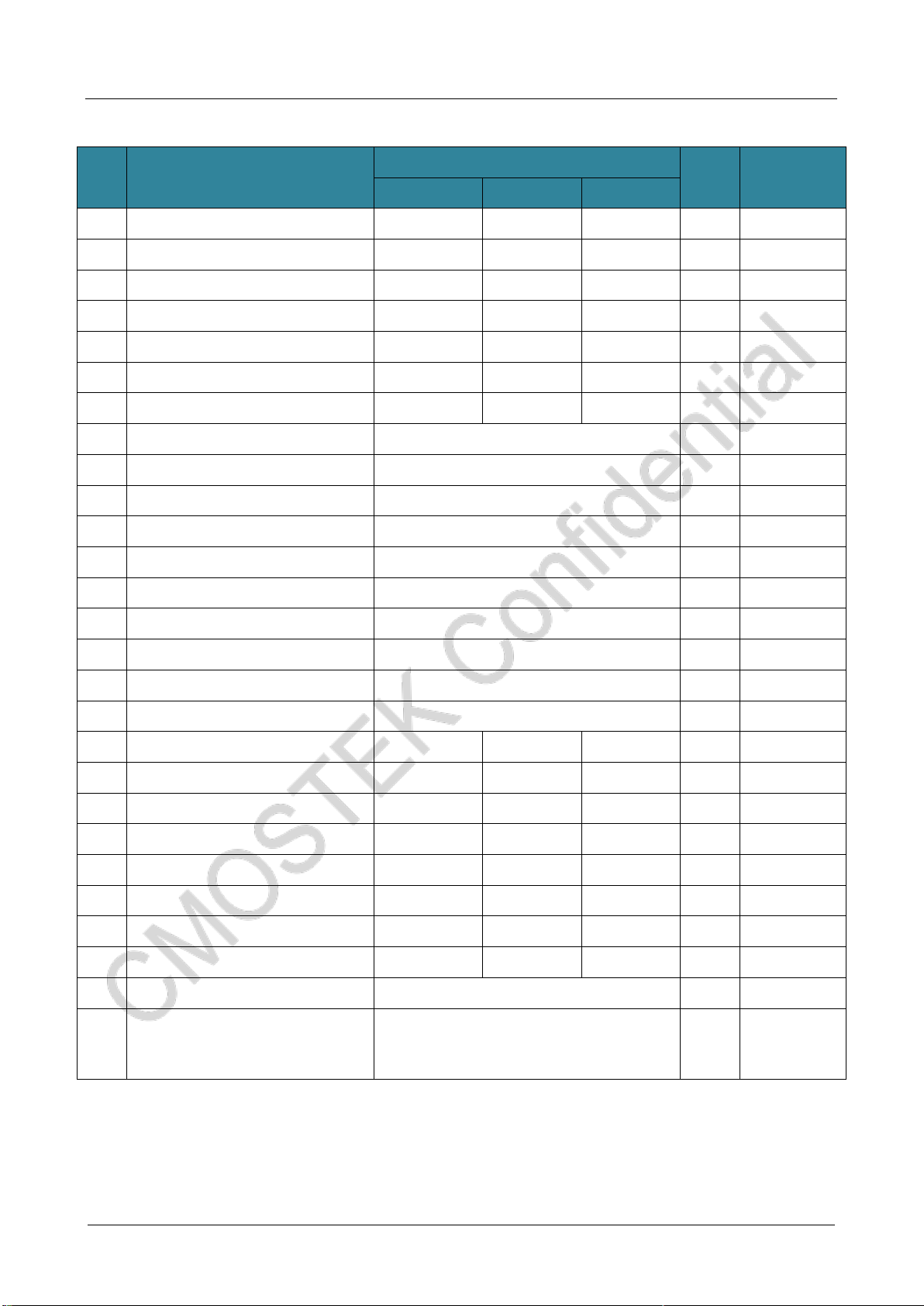
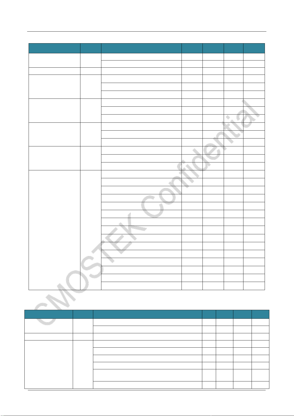
Table1. CMT2380F64 resources list
Memory
Analog peripheral
Digital peripheral
Package
ROM
RAM
ADC
PDR
RTC
WDT
Timer
UART
SPI
I2C
I2S
GPIO
64 KB
Flash
8 KB
12 bits x 6-ch
1Msps
√
1
1
5
2xUSART
1xLPUART
2
2
1
19+4
QFN40
64 KB
Flash
8 KB
12 bits x 6-ch
1Msps
√
1
1
5
2xUSART
1xLPUART
2
2
1
25+4
QFN48

CMT2380F64
www. cmostek.com
Rev 0.3 | 4 / 83
NC
RFIP
RFIN
RFO
RF_AVDD
RF_DGND
RF_DVDD
GPIO3
PC13
PC14
PC15
NRST
MCU_VDDA
PA0
PA1
PA2
PA3
PA4
PA6
GND
MCU_VDD
PB13
PB14
PB15
PA8
PA9
PA10
PA11
PA12
PA13
PA14
PB3/RF_SCK
PB4/RF_SDA
PB6/RF_CSB
PB7/RF_FCSB
NC
XI
XO
GPIO2
GPIO1
CMT2380F64
VCC
VCC
VCC
L5 L4
C3 C2
L3 L2
L7 L8
L6
C7
C6
C1 L1
C4 C5
Y1
26MHz
C8 C9 C10 C11
C12 C13
C14 C15
C16
R1
Figure1.CMT2380F64 (QFN 40 5x5) Typical application diagram (20 dBm power output)
NC
RFIP
RFIN
RFO
RF_AVDD
RF_DGND
RF_DVDD
GPIO3
PC13
PC14
PF0
NRST
MCU_VSS
MCU_VDD
MCU_VDDA
PA0
PA1
PA2
PA3
PA4
PA6
PA7
PB12
PB13
PB14
PB15
PA8
PA9
PA10
PA11
BOOT0
PB3/RF_SCK
PB4/RF_SDA
PB6/RF_CSB
PB7/RF_FCSB
PB8
XI
XO
GPIO2
GPIO1
CMT2380F64
VCC
VCC
L5 L4
C3 C2
L3 L2
L7 L8
L6
C7
C6
C1 L1
C4 C5
Y1
26MHz
C8 C9 C10 C11
C12 C13
C16
R1
NC
PC15
PF1
NC
PA12
PA13
PA14
PA15
Figure 2.CMT2380F64(QFN 48 6x6)Typical application diagram (20 dBm power output)
CMT2380F64
www. cmostek.com
Rev 0.3 | 5 / 83
No.
Description
Component value
Unit
Supplier
434 MHz
868 MHz
915 MHz
C1
±5%, 0402 NP0, 50 V
15
18
18
pF
-
C2
±5%, 0402 NP0, 50 V
3
3.6
3.6
pF
-
C3
±5%, 0402 NP0, 50 V
6.2
3.3
3.3
pF
-
C4
±5%, 0402 NP0, 50 V
24
24
24
pF
-
C5
±5%, 0402 NP0, 50 V
24
24
24
pF
-
C6
±5%, 0402 NP0, 50 V
4.7
2
1.8
pF
-
C7
±5%, 0402 NP0, 50 V
4.7
2
1.8
pF
-
C8
±20%, 0603 X7R, 25 V
4.7
uF
-
C9
±5%, 0402 NP0, 50 V
470
pF
-
C10
±20%, 0402 X7R, 25 V
0.1
uF
C11
±20%, 0402 X7R, 25 V
0.1
uF
C12
±20%, 0402 X7R, 25 V
0.1
uF
-
C13
±20%, 0603 X7R, 25 V
1
uF
-
C14
±20%, 0402 X7R, 25 V
0.1
uF
-
C15
±20%, 0603X7R, 25 V
1
uF
-
C16
±20%, 0402 X7R, 25 V
0.1
uF
R1
±5%, 0603 Chip Resistor
10
kΩ
L1
±10%, 0603 Multi-layer Chip Inductor
180
100
100
nH
Sunlord SDCL
L2
±10%, 0603 Multi-layer Chip Inductor
22
12
12
nH
Sunlord SDCL
L3
±10%, 0603 Multi-layer Chip Inductor
15pF
15
15
nH
Sunlord SDCL
L4
±10%, 0603 Multi-layer Chip Inductor
33
6.2
6.2
nH
Sunlord SDCL
L5
±10%, 0603 Multi-layer Chip Inductor
33
6.2
6.2
nH
Sunlord SDCL
L6
±10%, 0603 Multi-layer Chip Inductor
27
15
15
nH
Sunlord SDCL
L7
±10%, 0603 Multi-layer Chip Inductor
27
15
15
nH
Sunlord SDCL
L8
±10%, 0603 Multi-layer Chip Inductor
68
12
12
nH
Sunlord SDCL
Y1
±10 ppm, SMD32*25 mm
26
MHz
U1
CMT2380F64, Ultra low power
consumption Sub-1 GHz Wireless
transceiver micro-controller
-
-
CMOSTEK
CMT2380F64
www. cmostek.com
Rev 0.3 | 6 / 83
Table of Contents
1Electrical Characteristic ......................................................................................................................8
1.1 Recommended Operation Condition......................................................................................................................8
1.2 Absolute Maximum Rating.....................................................................................................................................8
1.3 Power Consumption ..............................................................................................................................................9
1.4 RF Receiver Specification .....................................................................................................................................9
1.5 RF Transmitter Specification................................................................................................................................11
1.6 Settling Time of RF Status Switching...................................................................................................................11
1.7 RF Frequency Synthesizer ..................................................................................................................................12
1.8 Crystal Oscillator Specification ............................................................................................................................13
1.9 Controller Reset and Power Control Module Specification .................................................................................13
1.10 Controller Embedded Reference Voltage............................................................................................................13
1.11 Controller Working Current Characteristic ...........................................................................................................14
1.12 External Clock Source Charateristic....................................................................................................................16
1.13 Controller internal clock source characteristics...................................................................................................20
1.14 Controller low-power mode wake-up time...........................................................................................................20
1.15 PLL characteristics..............................................................................................................................................21
1.16 FLASH characteristics.........................................................................................................................................21
1.17 I/O port characteristic...........................................................................................................................................22
1.18 MCU_NRST Pin Characteristics .........................................................................................................................23
1.19 TIM characteristic ................................................................................................................................................24
1.20 I2C Characteristic................................................................................................................................................24
1.21 SPI/I2S Characteristic..........................................................................................................................................26
1.22 ADC Characteristic..............................................................................................................................................30
1.23 Operational Amplifier(OPAMP)Characteritic...................................................................................................31
1.24 COMP Characteristic...........................................................................................................................................32
1.25 Temperature Sensor(TS) Characteristics............................................................................................................33
1.26 Rx Current VS. Supply Voltage...........................................................................................................................33
1.27 Rx Current/Voltage vs. Temperature...................................................................................................................34
1.28 Sensitivity vs. Supply Voltage..............................................................................................................................35
1.29 Sensitivity vs. Tmeperature .................................................................................................................................35
1.30 Tx Power vs. Supply Voltage...............................................................................................................................36
1.31 Tx Phase Noise ...................................................................................................................................................37
2Pin Description...................................................................................................................................38
3Chip Frame..........................................................................................................................................46
4Sub-G Transceiver..............................................................................................................................47
4.1 Transmitter...........................................................................................................................................................47
4.2 Receiver ..............................................................................................................................................................48
4.3 Power-on Reset (POR)........................................................................................................................................48
4.4 Crystal Oscillator..................................................................................................................................................49
4.5 Low power frequency oscillator(LPOSC)........................................................................................................49
4.6Internal Low Power Detection..............................................................................................................................49
4.7 Received Signal Strength Indicator(RSSI)......................................................................................................49
4.8 Phase Jump Detector(PJD)............................................................................................................................50
4.9 Clock Data Recovery(CDR)............................................................................................................................51
4.10 Fast Frequncy Hopping .......................................................................................................................................51
4.11 Chip Operation.....................................................................................................................................................51
4.11.1 SPI Interface..........................................................................................................................................51
4.11.2 FIFO Interface .......................................................................................................................................52
4.11.3 Transceiver working status,timing and power consumption...................................................................54
4.11.4 GPIO Function and Interrupt Mapping...................................................................................................57
5Function Description .........................................................................................................................60
5.1 Memory................................................................................................................................................................60
5.1.1 Embedded flash memory.......................................................................................................................60
5.1.2 Embedded SRAM..................................................................................................................................60
5.1.3 Nested vectored interrupt controller(NVIC).......................................................................................61
5.2 Extended interrupt/ event controller(EXTI)......................................................................................................61
5.3 Clock System.......................................................................................................................................................61
5.4 Boot Modes..........................................................................................................................................................62
5.5 Power supply scheme..........................................................................................................................................62
5.6 Programmable voltage monitor............................................................................................................................63

CMT2380F64
www. cmostek.com
Rev 0.3 | 7 / 83
5.7 Low Power Mode.................................................................................................................................................63
5.8 Direct Memory Access(DMA)..........................................................................................................................63
5.9 Real Time Clock(RTC)....................................................................................................................................63
5.10 Timer and Watch Dog..........................................................................................................................................64
5.10.1 Basic timer TIM6....................................................................................................................................64
5.10.2 General purpose timer TIM3..................................................................................................................64
5.10.3 Low power timer (LPTIM) ......................................................................................................................66
5.10.4 Adcanced control timer (TIM1/TIM8) .....................................................................................................66
5.10.5 Systick...................................................................................................................................................67
5.10.6 Watchdog Timer (WDG).........................................................................................................................67
5.11 I2C Bus Interface.................................................................................................................................................67
5.12 Universal synchronous asynchronous receiver transmitter(USART)..............................................................68
5.13 Serial Perigheral Interface(SPI)......................................................................................................................69
5.14 Synchronous Serial Interchip Sound(I2S).......................................................................................................70
5.15 General purpose input/output(GPIO)..............................................................................................................71
5.16 Analog to digital converter(ADC).....................................................................................................................71
5.17 Operational Amplifier(OPAMP).......................................................................................................................73
5.18 Analog Comparator(COMP)............................................................................................................................73
5.19 Temperature Sensor(TS)................................................................................................................................74
5.20 BEEPER..............................................................................................................................................................74
5.21 HDIV/ SQRT........................................................................................................................................................74
5.22 Cyclic Redundancy Check Calculation Unit(CRC)..........................................................................................74
5.23 Unique device ID(UID)....................................................................................................................................74
5.24 Serial wire SWD debug port(SWD).................................................................................................................75
6Order Information...............................................................................................................................76
7Package Outline..................................................................................................................................77
8Silk Printing Information....................................................................................................................79
9Relevant Documents..........................................................................................................................81
10 Revision...............................................................................................................................................82
11 Contacts ..............................................................................................................................................83
CMT2380F64
www. cmostek.com
Rev 0.3 | 8 / 83
1 Electrical Characteristic
VDD= 3.3 V,TOP= 25 °C,FRF = 433.92 MHz, sensitivity is measured by receiving a PN9 coded data and matching
impedance to 50Ω under 0.1% BER standard.Unless otherwise stated, all results are tested on the CMT2380F17-EM
evaluation board.
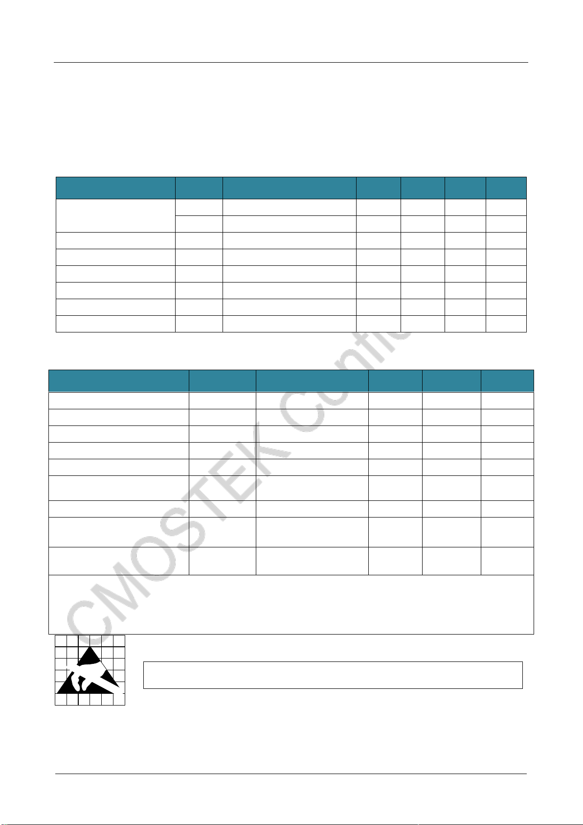
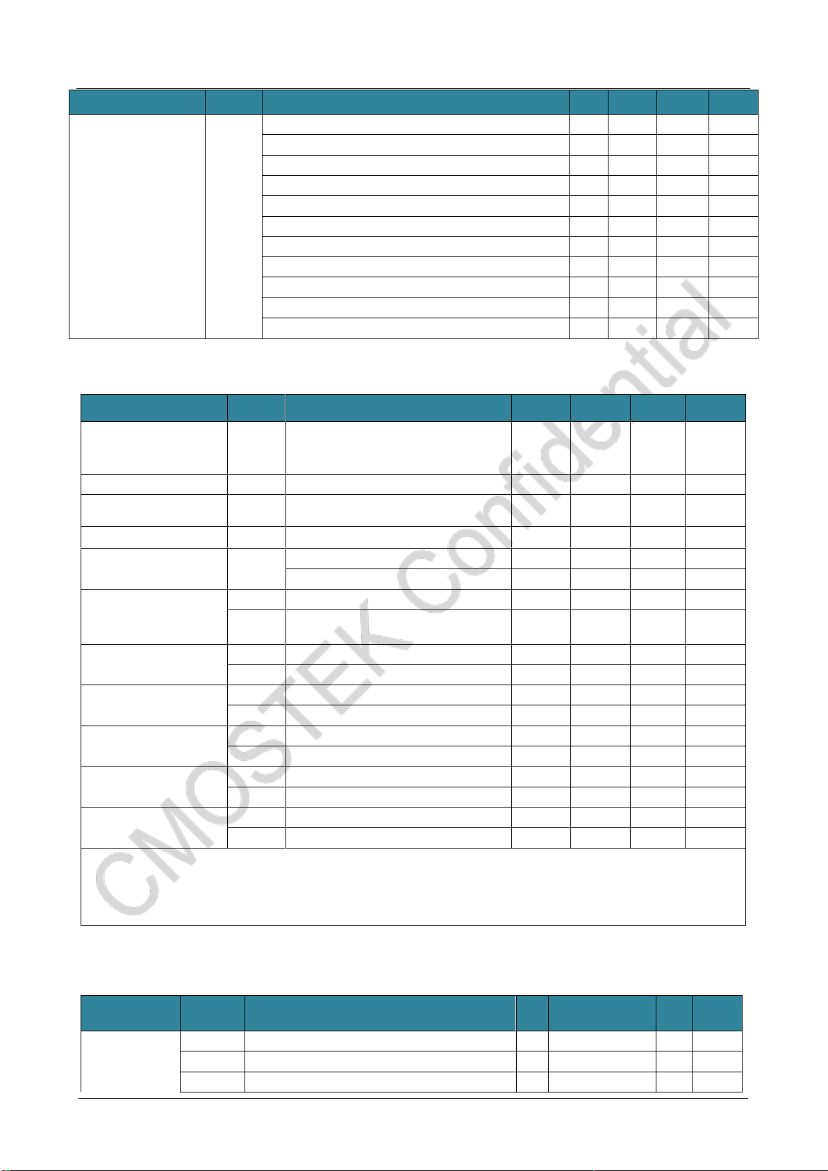
1.1 Recommended Operation Condition
Parameter
Symbol
Condition
Min.
Typ.
Max.
Unit
Operating power voltage
VDD-RF
1.8
3.6
V
VMCU
CPU workingrate 0-48 MHz
1.8
3.6
V
Operating temperature
TOP
-40
85
℃
RF power voltage slope
VRF-PSR
1
mV/us
Voltage slope
VMCU-PSR
10
mV/us
AHB clock frequency
fHCLK
0
48
MHz
APB1 clock frequency
fPCLK1
0
48
MHz
APB2 clock frequency
fPCLK2
0
48
MHz
1.2 Absolute Maximum Rating
Parameter
Symbol
Conditions
Min
Max
Unit
Supply Voltage
VDD
-0.3
3.6
V
Interface Voltage
VIN
-0.3
3.6
V
Junction Temperature
TJ
-40
125
℃
Storage Temperature
TSTG
-50
150
℃
Soldering Temperature
TSDR
Retentionatleast30s
255
℃
ESD Rating[2]
Human body mode(HBM)
-2
2
kV
Latch-up Current
@ 85 ℃
-100
100
mA
MCU-VDD maximum current to
Ground
200
mA
MCU pin maximum sink current
16
mA
Notes:
[1]. Exceeding theAbsolute Maximum Ratings may cause permanent damage to the equipment. This value is a pressure rating
and does not imply that the function of the equipment is affected under this pressure condition, but if it is exposed to absolute
maximum ratings for extended periods of time, it may affect equipment reliability.
[2]. CMT2380F64 is a high performance RF integrated circuit. The operation and assembly of this chip should only be performed
on a workbench with good protection.
Caution! ESD sensitive device. Precaution should be used when handling the device in order to
prevent permanent damage.
CMT2380F64
www. cmostek.com
Rev 0.3 | 9 / 83
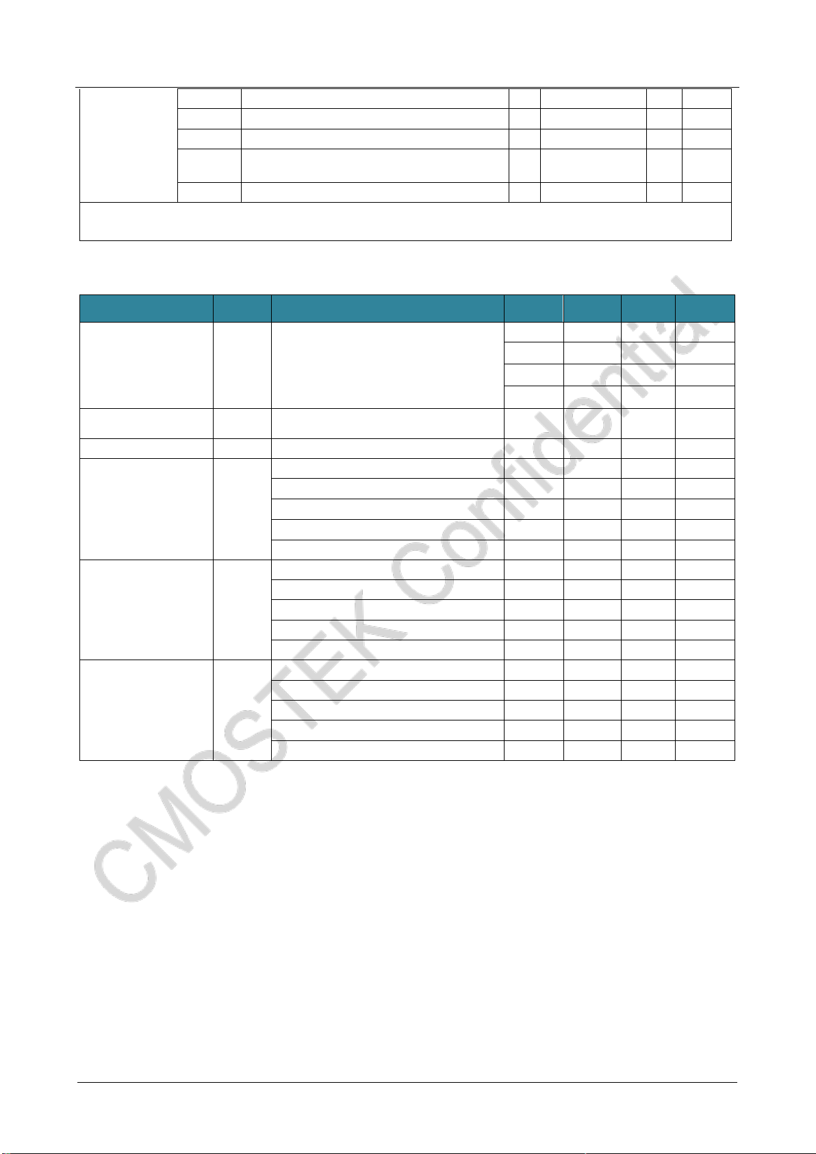
1.3 Power Consumption
Parameter
Symbol
Condition
Min.
Typ.
Max.
Unit
Sleep current
ISLEEP
Sleep mode, sleep timer is off
300
nA
Sleep mode, sleep timer is on
800
nA
Standby current
IStandby
Crystal oscillator is on
1.45
mA
RFS current
IRFS
433 MHz
5.7
mA
868 MHz
5.8
mA
915 MHz
5.8
mA
TFS current
ITFS
433 MHz
5.6
mA
868 MHz
5.9
mA
915 MHz
5.9
mA
RX current (high
performance)
IRx-HP
FSK, 433 MHz, 10 kbps,10 kHz FDEV
8.5
mA
FSK, 868 MHz, 10 kbps, 10 kHz FDEV
8.6
mA
FSK, 915 MHz, 10 kbps,10 kHz FDEV
8.9
mA
RX current (low power
consumption)
IRx-LP
FSK, 433 MHz, 10 kbps, 10 kHz FDEV
7.2
mA
FSK, 868 MHz, 10 kbps, 10 kHz FDEV
7.3
mA
FSK, 915 MHz, 10 kbps, 10 kHz FDEV
7.6
mA
TX current
ITx
FSK, 433 MHz, +20 dBm (Direct Tie)
72
mA
FSK, 433 MHz, +20 dBm (RF switch)
77
mA
FSK, 433 MHz, +13 dBm (Direct Tie)
23
mA
FSK, 433 MHz, +10 dBm (Direct Tie)
18
mA
FSK, 433 MHz, - 10 dBm (Direct Tie)
8
mA
FSK, 868 MHz, +20 dBm (Direct Tie)
87
mA
FSK, 868 MHz, +20 dBm (RF switch)
80
mA
FSK, 868 MHz, +13 dBm (Direct Tie)
27
mA
FSK, 868 MHz, +10 dBm (Direct Tie)
19
mA
FSK, 868 MHz, - 10 dBm (Direct Tie)
8
mA
FSK, 915 MHz, +20 dBm (Direct Tie)
70
mA
FSK, 915 MHz, +20 dBm (RF switch)
75
mA
FSK, 915 MHz, +13 dBm (Direct Tie)
28
mA
FSK, 915 MHz, +10 dBm (Direct Tie)
19
mA
FSK, 915 MHz, - 10 dBm (Direct Tie)
8
mA
Notes: The above power consumption is only RF workingcurrent, excluding the workingcurrentof thecontrollerpart.
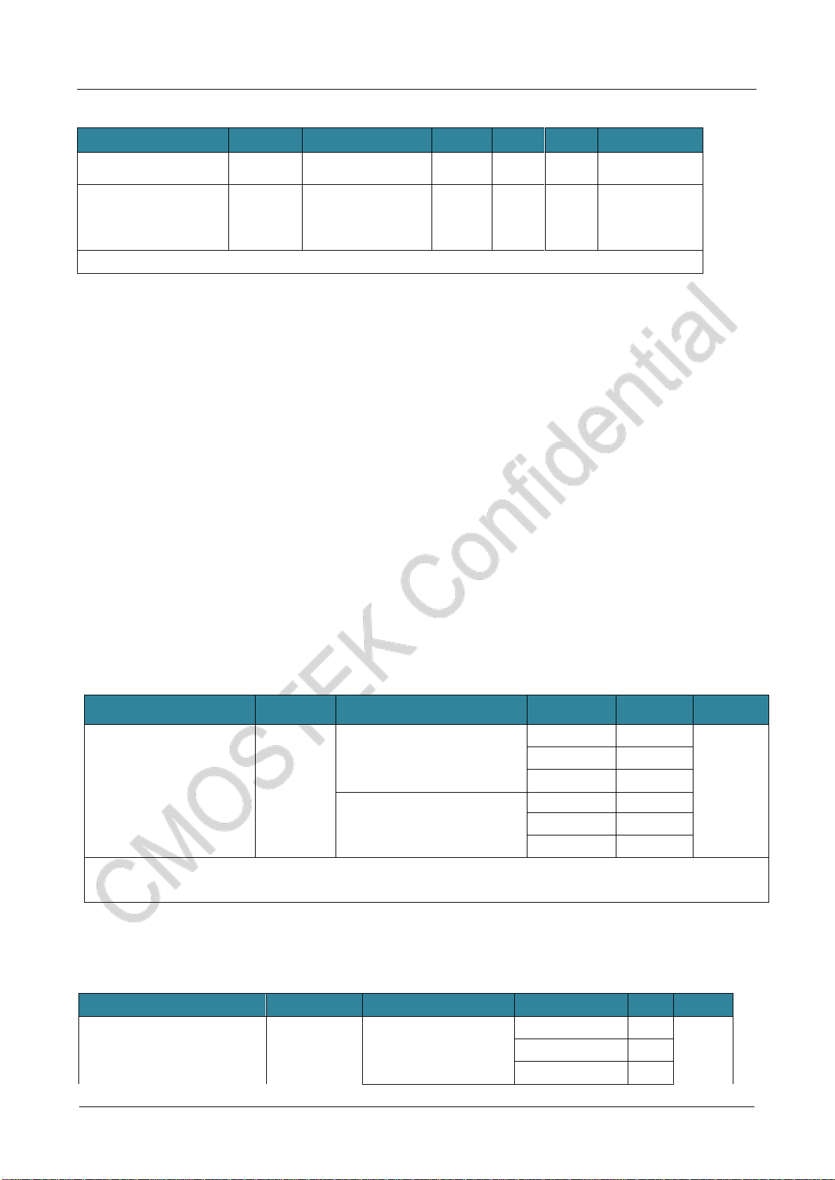
1.4 RF Receiver Specification
Parameter
Symbol
Condition
Min.
Typ.
Max.
Unit
Data rate
DR
OOK
0.5
40
kbps
FSK and GFSK
0.5
300
kbps
Deviation
FDEV
FSK and GFSK
2
200
kHz
Sensitivity @ 433 MHz
S433-HP
DR = 2.0 kbps, FDEV = 10 kHz
-121
dBm
DR = 10 kbps, FDEV = 10 kHz
-116
dBm
DR = 10 kbps, FDEV = 10 kHz (Low power setting)
-115
dBm
DR = 20 kbps, FDEV = 20 kHz
-113
dBm
DR = 20 kbps, FDEV = 20 kHz (Low power setting)
-112
dBm
DR = 50 kbps, FDEV = 25 kHz
-111
dBm

CMT2380F64
www. cmostek.com
Rev 0.3 | 10 / 83
Parameter
Symbol
Condition
Min.
Typ.
Max.
Unit
DR =100 kbps, FDEV = 50 kHz
-108
dBm
DR =200 kbps, FDEV = 100 kHz
-105
dBm
DR =300 kbps, FDEV = 100 kHz
--103
dBm
Sensitivity @ 868 MHz
S868-HP
DR = 2.0 kbps, FDEV = 10 kHz
-119
dBm
DR = 10 kbps, FDEV = 10 kHz
-113
dBm
DR = 10 kbps, FDEV = 10 kHz (Low power setting)
-111
dBm
DR = 20 kbps, FDEV = 20 kHz
-111
dBm
DR = 20 kbps, FDEV = 20 kHz (Low power setting)
-109
dBm
DR = 50 kbps, FDEV = 25 kHz
-108
dBm
DR =100 kbps, FDEV = 50 kHz
-105
dBm
DR =200 kbps, FDEV = 100 kHz
-102
dBm
DR =300 kbps, FDEV = 100 kHz
-99
dBm
Sensitivity @ 915 MHz
S915-HP
DR = 2.0 kbps, FDEV = 10 kHz
-117
dBm
DR = 10 kbps, FDEV = 10 kHz
-113
dBm
DR = 10 kbps, FDEV = 10 kHz (Low power setting)
-111
dBm
DR = 20 kbps, FDEV = 20 kHz
-111
dBm
DR = 20 kbps, FDEV = 20 kHz (Low power setting)
-109
dBm
DR = 50 kbps, FDEV = 25 kHz
-109
dBm
DR =100 kbps, FDEV = 50 kHz
-105
dBm
DR =200 kbps, FDEV = 100 kHz
-102
dBm
DR =300 kbps, FDEV = 100 kHz
--99
dBm
Saturation Input Signal
Level
PLVL
20
dBm
Image Rejection Ratio
IMR
FRF=433 MHz
35
dBc
FRF=868 MHz
33
dBc
FRF=915 MHz
33
dBc
RX Channel Bandwidth
BW
RX channel bandwidth
50
500
kHz
Co-channel Rejection
Ratio
CCR
DR = 10 kbps, FDEV = 10 kHz; Interfere with the same
modulation
-7
dBc
Adjacent Channel
Rejection Ratio
ACR-I
DR = 10 kbps, FDEV = 10 kHz; BW=100 kHz, 200 kHz
Channel spacing, interfere with the same modulation
30
dBc
Alternate Channel
Rejection Ratio
ACR-II
DR = 10 kbps, FDEV = 10 kHz; BW=100 kHz, 400 kHz
Channel spacing, interfere with the same modulation
45
dBc
Blocking Rejection
Ratio
BI
DR = 10 kbps, FDEV = 10 kHz; ±1 MHz Deviation,
continuous wave interference
70
dBc
DR = 10 kbps, FDEV = 10 kHz; ±2 MHz Deviation,
continuous wave interference
72
dBc
DR = 10 kbps, FDEV = 10 kHz; ±10 MHz Deviation,
continuous wave interference
75
dBc
Input3rd Order Intercept
Point
IIP3
DR = 10 kbps, FDEV = 10 kHz; 1 MHz 和2 MHz Deviation
dual tone test, maximum system gain setting.
-25
dBm
RSSI Range
RSSI
-120
20
dBm
More Sensitivity
(Typical Configuration)
433.92 MHz, DR = 1.2 kbps, FDEV = 5 kHz
-122.9
dBm
433.92 MHz, DR = 1.2 kbps, FDEV = 10 kHz
-121.8
dBm
433.92 MHz, DR = 1.2 kbps, FDEV = 20 kHz
-119.5
dBm
433.92 MHz, DR = 2.4 kbps, FDEV = 5 kHz
-120.6
dBm
433.92 MHz, DR = 2.4 kbps, FDEV = 10 kHz
-120.3
dBm
433.92 MHz, DR = 2.4 kbps, FDEV = 20 kHz
-119.7
dBm
CMT2380F64
www. cmostek.com
Rev 0.3 | 11 / 83
Parameter
Symbol
Condition
Min.
Typ.
Max.
Unit
433.92 MHz, DR = 9.6 kbps, FDEV = 9.6 kHz
-116.0
dBm
433.92 MHz, DR = 9.6 kbps, FDEV = 19.2 kHz
-116.1
dBm
433.92 MHz, DR = 20 kbps, FDEV = 10 kHz
-114.2
dBm
433.92 MHz, DR = 20 kbps, FDEV = 20 kHz
-113.0
dBm
433.92 MHz, DR = 50 kbps, FDEV = 25 kHz
-110.6
dBm
433.92 MHz, DR = 50 kbps, FDEV = 50 kHz
-109.0
dBm
433.92 MHz, DR = 100 kbps, FDEV = 50 kHz
-107.8
dBm
433.92 MHz, DR = 200 kbps, FDEV = 50 kHz
-103.5
dBm
433.92 MHz, DR = 200 kbps, FDEV = 100 kHz
-104.3
dBm
433.92 MHz, DR = 300 kbps, FDEV = 50 kHz
-98.0
dBm
433.92 MHz, DR = 300 kbps, FDEV = 150 kHz
-101.6
dBm
1.5 RF Transmitter Specification
Parameter
Symbol
Condition
Min.
Typ.
Max.
Unit
Output power
POUT
Specific peripheral materials
are needed for
different frequency bands
-20
+20
dBm
Output power step
PSTEP
1
dB
GFSK Gaussian filter
coefficient
BT
0.3
0.5
1.0
-
Output power variation
POUT-TOP
Temperature from -40 to +85℃
1
dB
Transmitting spurious
emission
POUT= +13 dBm,433 MHz, FRF<1 GHz
-54
dBm
1 GHz to 12.75 GHz, with harmonic
-36
dBm
Harmonic output for
FRF= 433 MHz[1]
H2433
2nd harmonic +20 dBm POUT
-46
dBm
H3433
3nd harmonic +20 dBm POUT
-50
dBm
Harmonic output
for FRF= 868 MHz[1]
H2868
2nd harmonic +20 dBm POUT
-43
dBm
H3868
3ndharmonic +20 dBm POUT
-52
dBm
Harmonic output
for FRF= 915 MHz[1]
H2915
2ndharmonic +20 dBm POUT
-48
dBm
H3915
3ndharmonic +20 dBm POUT
-53
dBm
Harmonic output
for FRF= 433 MHz[1]
H2433
2ndharmonic +13 dBm POUT
-52
dBm
H3433
3ndharmonic +13 dBm POUT
-52
dBm
Harmonic output
for FRF= 868 MHz[1]
H2868
2ndharmonic +13 dBm POUT
-52
dBm
H3868
3ndharmonic +13 dBm POUT
-52
dBm
Harmonic output
for FRF= 915 MHz[1]
H2915
2ndharmonic +13 dBm POUT
-52
dBm
H3915
3ndharmonic +13 dBm POUT
-52
dBm
Notes:
[1]. The harmonic parametervalues mainly depend on the quality of the hardware matching network. The above data is measured
based on the CMT2380F17-EM module; testingresults will be differently when it is done on the self-designed PCB.
1.6 Settling Time of RF Status Switching
Parameter
Symbol
Condition
Min.
Typ.
Max.
Unit
TSLP-RX
From Sleep to RX
1000
us
TSLP-TX
From Sleep toTX
1000
us
TSTB-RX
From Standby to RX
350
us
CMT2380F64
www. cmostek.com
Rev 0.3 | 12 / 83
Settling time
TSTB-TX
From Standby toTX
350
us
TRFS-RX
From RFS to RX
20
us
TTFS-RX
From TFS toTX
20
us
TTX-RX
From TX to RX
(Ramp Down time needs 2 Tsymbol)
2 Tsymbol +350
us
TRX-TX
From RX to TX
350
us
Notes:
[1]. Both of TSLP-RX and TSLP-TX are depend on the crystal oscillator startup time, which is mainly related to the crystal itself.
1.7 RF Frequency Synthesizer
Parameter
Symbol
Condition
Min.
Typ.
Max.
Unit
Frequency range
FRF
Different matching network is required
760
1020
MHz
380
510
MHz
190
340
MHz
127
170
MHz
Synthesizer frequency
resolution
FRES
25
Hz
Frequency tuning time
TUNE
150
us
Phase noise@ 433 MHz
PN433
10 kHz frequency deviation
-94
dBc/Hz
100 kHz frequency deviation
-99
dBc/Hz
500 kHz frequency deviation
-118
dBc/Hz
1 MHz frequency deviation
-127
dBc/Hz
10 MHz frequency deviation
-134
dBc/Hz
Phase noise@ 868 MHz
PN868
10 kHz frequency deviation
-92
dBc/Hz
100 kHz frequency deviation
-95
dBc/Hz
500 kHz frequency deviation
-114
dBc/Hz
1 MHz frequency deviation
-121
dBc/Hz
10 MHz frequency deviation
-130
dBc/Hz
Phase noise@ 915 MHz
PN915
10 kHz frequency deviation
-89
dBc/Hz
100 kHz frequency deviation
-92
dBc/Hz
500 kHz frequency deviation
-111
dBc/Hz
1 MHz frequency deviation
-121
dBc/Hz
10 MHz frequency deviation
-130
dBc/Hz
t

CMT2380F64
www. cmostek.com
Rev 0.3 | 13 / 83
1.8 Crystal Oscillator Specification
Parameter
Symbol
Condition
Min.
Typ.
Max.
Unit
Crystal frequency[1]
FXTAL
26
MHz
Frequency tolerance[2]
ppm
20
ppm
Load capacitance
CLOAD
15
pF
Equivalentresistance
Rm
60
Ω
Start-up time[3]
XTAL
400
us
Notes:
[1]. CMT2380F64 can use the external reference clock to drive the XIN pin through the coupling capacitor. The peak value of the
external clock signal is between 0.3 V and 0.7 V.
[2]. The value includes (1) initial error;(2) crystal load;(3)aging; and (4) change with temperature. The acceptable crystal frequency
tolerance is limited by the receiver bandwidth and the RF frequency offset between the transmitter and the receiver.
[3]. The parameter is largely related to the crystal.
1.9 Controller Reset and Power Control Module Specification
Parameter
Symbol
Condition
Min.
Typ.
Max.
Unit
Rising
VPVD
PLS[3:0]=0
1.8
1.88
1.96
V
Falling
PLS[3:0]=0
1.7
1.78
1.86
Rising
PLS[3:0]=1
2
2.08
2.16
Falling
PLS[3:0]=1
1.9
1.98
2.06
Rising
PLS[3:0]=2
2.2
2.28
2.36
Falling
PLS[3:0]=2
2.1
2.18
2.26
Rising
PLS[3:0]=3
2.4
2.48
2.56
Falling
PLS[3:0]=3
2.3
2.38
2.46
Rising
PLS[3:0]=4
2.6
2.68
2.76
Falling
PLS[3:0]=4
2.5
2.58
2.66
Rising
PLS[3:0]=5
2.8
2.88
2.96
Falling
PLS[3:0]=5
2.7
2.78
2.86
Rising
PLS[3:0]=6
3
3.08
3.16
Falling
PLS[3:0]=6
2.9
2.98
3.06
Rising
PLS[3:0]=7
3.2
3.28
3.36
Falling
PLS[3:0]=7
3.1
3.18
3.26
Rising
PLS[3:0]=8
3.4
3.48
3.56
Falling
PLS[3:0]=8
3.3
3.38
3.46
Rising
PLS[3:0]=9
3.6
3.68
3.76
Falling
PLS[3:0]=9
3.5
3.58
3.66
Rising
PLS[3:0]=10
3.8
3.88
3.96
Falling
PLS[3:0]=10
3.7
3.78
3.86
PVD delay
VPVDhyst(2)
-
80
100
125
mV
VDD power up/down
VPOR
-
-
1.53
-
V
1.10 Controller Embedded Reference Voltage
t
CMT2380F64
www. cmostek.com
Rev 0.3 | 14 / 83
Parameter
Symbol
Condition
Min.
Typ.
Max.
Unit
Embeddedreferencevoltage
VREFINT
-40℃<TA<+105℃
1.16
1.21
1.26
V
Sampling time of ADC
when internal
referencevoltage read out
TS_vrefint(1)
PLS [2:0]=001
( rising edge)
-
10
-
μs
1. The minimum sampling time was obtained from multiple cycles in application.
1.11Controller Working Current Characteristic
Current consumption is a combination of several parameters and factors, including operating voltage, ambient temperature, I/O pin
load, product software configuration, operating frequency, I/O pin turnover rate, program location in memory, and code executed,
etc.
⚫Maximum current consumption
The micro-controller is in the following conditions:
◼All I / O pins are in input mode and are connected to a static level VDD or VSS with no load.
◼All peripherals are disabled, unless otherwise noted.
◼The access time of the flash memory is adjusted to the fHCLK frequency (0 wait period for 0 to 18 MHz, 1 wait
period for 18 to 36 MHz, 2 waiting period for over 36 MHz).
◼The command pre-fetch function is turned on (notes: this parameter must be set before the clock and bus
frequency distribution is set).
◼When the peripherals are turned on:fPCLK1 = fHCLK, fPCLK2 = fHCLK.
Maximum current consumption in operating mode and the data processing code
is run from the internal flash memory
Parameter
Sign
Condition
HCLK
Typical Value
(1)
Unit
Operating current in the
operating mode
IDD
External clock(2) ,enable all
the peripherals
48 MHz
8.4
mA
24 MHz
5.0
8 MHz
2.8
External clock(2),disable all
the peripherals
48 MHz
5.0
24 MHz
3.3
8 MHz
2.3
1. Guaranteed by design and comprehensive assessment, not tested in production.
2. External clock, PLL is enabled when the fHCLK is 24 MHz or 48 MHz.
Maximum current consumption in operating mode, and
data processing code is run from the internal RAM
Parameter
Symbol
Condition
fHCLK
Typ. (1)
Unit
External clock(2) ,enable all
the peripherals
48 MHz
6.2
24 MHz
4.1
8 MHz
3.2
f
CMT2380F64
www. cmostek.com
Rev 0.3 | 15 / 83
Operating current
in the operating mode
IDD
External clock(2) ,disable all
the peripherals
48 MHz
4.4
mA
24 MHz
3.2
8 MHz
2.6
1. Guaranteed by design and comprehensive assessment, not tested in production.
2. External clock, PLL is enabled when the fHCLKis 24 MHz or 48 MHz.
Maximum current consumption in sleep mode,
and the code runs in the internal flash memory
Parameter
Symbol
Condition
HCLK
Typ. (1)
Unit
Working current in
sleep mode
IDD
External clock(2) ,enable all the peripherals
48 MHz
6.5
mA
24 MHz
3.9
8 MHz
2.0
External clock(2) ,disable all the peripherals
48 MHz
2.9
24 MHz
2.1
8 MHz
1.4
1. According to the comprehensive assessment, VDDmax and fHCLKmax enabling peripheral are the test condition.
2. External clock, PLL is enabled when the fHCLK is 24 MHz or 48 MHz.
Typical consumption in stop and sleep mode
Parameter
Symbol
Condition
Typ(1)
Max
Unit
VDD=3.3V
VDD=3.3V
SLEEP mode current
Kernel stopped, all peripherals including
Cortex-M0 core peripherals suchas NVIC,
system ticking clock (SysTick) still running
2.7
5
mA
STOP mode current
RTC is not running, SRAM, registers and all I/O
states retain
1.5
2.5
uA
PD mode current
VDD power down mode, 3 WAKEUP IO and
NRST can be awakened
0.5
1
uA
1. Typ/ Max value is tested under TA=25 ℃.
⚫Typical current consumption
MCU is under the following conditions:
◼All I / O pins are in input mode and are connected to a static level VDD or VSS with no load.
◼All peripherals are disabled, unless otherwise noted.
◼The access time of the flash memory is adjusted to the fHCLK frequency (0 wait period for 0 to 18 MHz, 1 wait
period for 18 to 36 MHz, 2 waiting period for over 36 MHz).
◼The command pre-fetch function is turned on (notes: this parameter must be set before the clock and bus
frequency distribution is set).
◼When the peripherals are turned on:fPCLK1 = fHCLK, fPCLK2 = fHCLK, fADCCLK = fPCLK2/3.
f

CMT2380F64
www. cmostek.com
Rev 0.3 | 16 / 83
Typical current consumption in operation mode,
with data processing code running from an internal Flash
Parameter
Symbol
Condition
fHCLK
Typ(1)
Unit
Enable all the
peripherals
Disable all the
peripherals
Supply current
in operating mode
IDD
External high speed clock (HSE,) using
AHBprefrequencytoreducethe
frequency
48 MHz
8.2
4.8
mA
24 MHz
5.0
3.3
8 MHz
2.7
2.1
Internal high speed RC oscillator (2)
(HSI),AHB pre-frequency to reduce
the frequency
48 MHz
7.6
4.3
mA
24 MHz
4.3
2.7
8 MHz
2.1
1.5
1. Typical value is tested under TA=25℃, VDD=3.3V.
2. The internal high-speed clock is 8 MHz,and PLL is enabled when fHCLK>8 MHz.
Typical current consumption in sleep mode, data processing code is run from internal Flash or RAM
Parameter
Symbol
Condition
fHCLK
Typ(1)
Unit
Enable all the
peripherals
Disable all the
peripherals
Working current in
sleep mode
IDD
External high speed clock
(HSE),using AHB
prefrequency to reduce the
frequency
48 MHz
6.3
2.7
mA
24 MHz
3.7
2.0
8 MHz
1.8
1.2
Internal high speed RC
oscillator(2) (HSI),AHB
pre-frequency to reduce the
frequency
48 MHz
5.7
2.1
mA
24 MHz
3.1
1.4
8 MHz
1.2
0.6
1. Typical value is tested under TA=25 ℃, VDD=3.3 V.
2. The internal high-speed clock is 8 MHz,and PLL is enabled when fHCLK>8 MHz.
1.12 External Clock Source Charateristic
⚫High-speed external user clock generated from external oscillation sources
The characteristic parameters in the following table are measured under a high-speed external clock source and the ambient
temperature and supply voltage meet the conditions in the following table.
High-speed external user clock features
Symbol
Parameter
Condition
Min
Typ
Max
Unit
fHSE_ext
User external clock frequency
-
4
8
20
MHz
VHSEH
OSC_IN input pin at high-level voltage(1)
0.7 VDD
-
VDD
V
VHSEL
OSC_IN input pin at low-level voltage(1)
VSS
-
0.3 VDD
tw(HSE)
OSC_IN high /low time(1)
16
-
-
ns
tr(LSE)
tf(LSE)
OSC_IN up/ down time(1)
-
-
20
Cin(HSE)
OSC_IN input capacitance(1)
5
pF

CMT2380F64
www. cmostek.com
Rev 0.3 | 17 / 83
DuCy(HSE)
Dutycycle(1)
45
-
55
%
IL
OSC_IN input leakage current(1)
VSS≤VIN≤VDD
-
-
±1
μA
•1.Guaranteed by design and comprehensive evaluation, not tested in production.
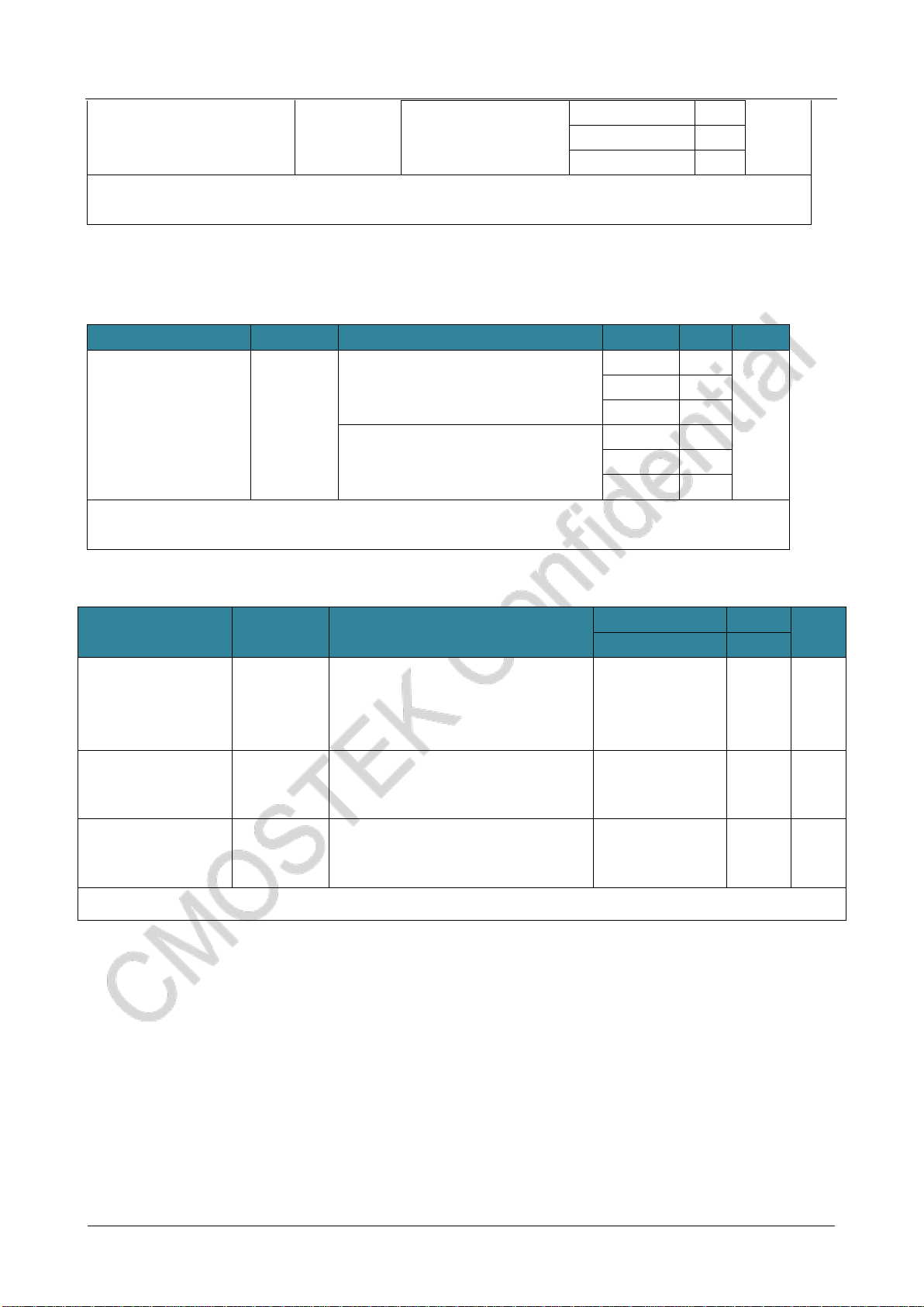
90%
10%
VHSEH
VHSEL
tr(HSE) tf(HSE)
THSE
tW(HSE) tW(HSE) t
External clock
source OSC_INfHSE_ext
The AC timing diagram of the external high-speed clock source
⚫Low-speed external user clock generated from external oscillation sources
Low-speed external user clock features
Symbol
Parameter
Condition
Min
Typ
Max
Unit
fLSE_ext
User external clock frequency
-
0
32.768
1000
KHz
VLSEH
OSC32_IN input pin at high-level
voltage(1)
0.7 VDD
-
VDD
V
VLSEL
OSC32_IN input pin at low-level
voltage(1)
VSS
-
0.3 VDD
tw(LSE)
OSC32_IN high /low time(1)
450
-
-
ns
tr(LSE)
tf(LSE)
OSC32_IN up/ down time(1)
-
-
10
DuCy(LSE)
Dutycycle(1)
30
-
70
%
IL
OSC32_IN input leakage current(1)
VSS≤VIN≤VDD
-
-
±1
μA
1. Guaranteed by design and comprehensive assessment, not tested in production。
CMT2380F64
www. cmostek.com
Rev 0.3 | 18 / 83
90%
10%
VLSEH
VLSEL
tr(LSE) tf(LSE)
TLSE
tW(LSE) tW(LSE) t
External clock
source OSC32_INfLSE_ext
The AC timing diagram of the external low-speed clock source
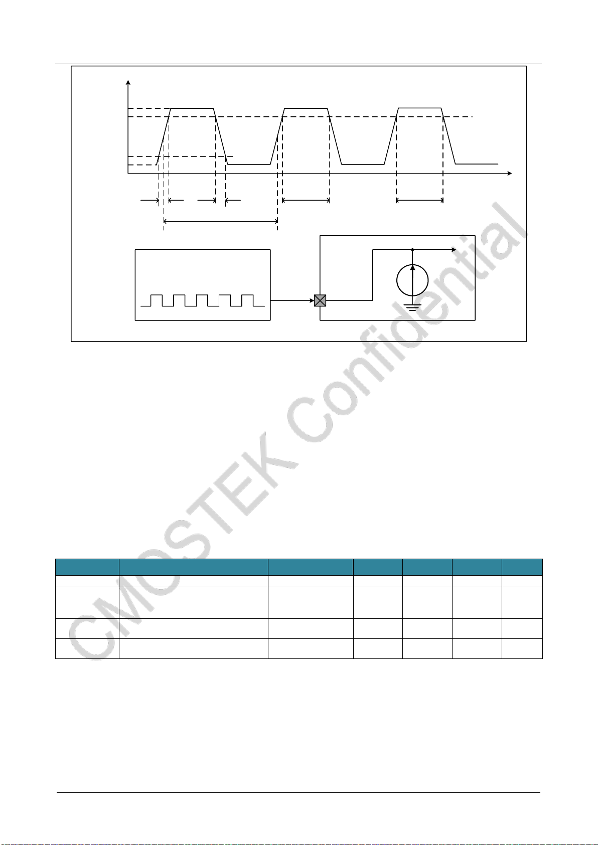
⚫A high-speed external clock generated by using a crystal / ceramic resonator
The high speed external clock (HSE) can be generated using an oscillatorconsisting of a 4~20 MHz crystal/ceramic
oscillator. The information given in this section is based on the use of typical external components listed in the table below.In
applications where the oscillator and load capacitance must be as close to the oscillator pin as possible to reduce output
distortion and stability time at startup. For detailed parameters of crystal oscillator (frequency, package, accuracy, etc.),
please consult the corresponding manufacturer (the crystal resonators mentioned here are usually referred to the passive
crystal oscillator).
HSE 4~20 MHz Oscillator Characteristic
Symbol
Parameter
Condition
Min
Typ
Max
Unit
fOSC_IN
Oscillator frequency
4
8
20
MHz
CL1
CL2(3)
The suggested load capacitance and
corresponding crystal serial resistance
(RS)
RS= 30 Ω
-
20
--
pF
i2
HSE drive current
VDD=3.3 V, VIN=VSS
30pF load
-
1.1
1.6
mA
tSU(HSE)(4)
Startup time
VDD is stable
3
ms
1. The parameters of the resonator are given by the crystal resonator manufacturer.
2. Guaranteed by design and comprehensive assessment, not tested in production.
3. For CL1 and CL2, it is recommended to use high quality ceramic dielectric capacitance (typically) between 5pF and 25pF
designed for high-frequency applications, and to select suitable crystals or resonators. Usually CL1 and CL2 have the same
parameters. Crystal manufacturers usually give parameters for load capacitance as serial combinations of CL1 and CL2. The
capacitive reactance of PCB and MCU pins should be taken into account when selecting CL1 and CL2.
4. tSU(HSE) is the startup time. It is measured from the time when HSE is enabled by software until a stable 8MHz oscillation is
obtained. This value is measured on a standard crystal resonator and can vary widely depending on the crystal manufacturer.
CMT2380F64
www. cmostek.com
Rev 0.3 | 19 / 83
CL2
CL1
8MHz
oscillator Gain
control
Integrated
capacitance
oscillator
OSC_IN
OSC_OUT
RF
fHSE
REXT
Typical applications of using 8MHz crystals
Note: The value of REXT is depended on the crystal characteristic.
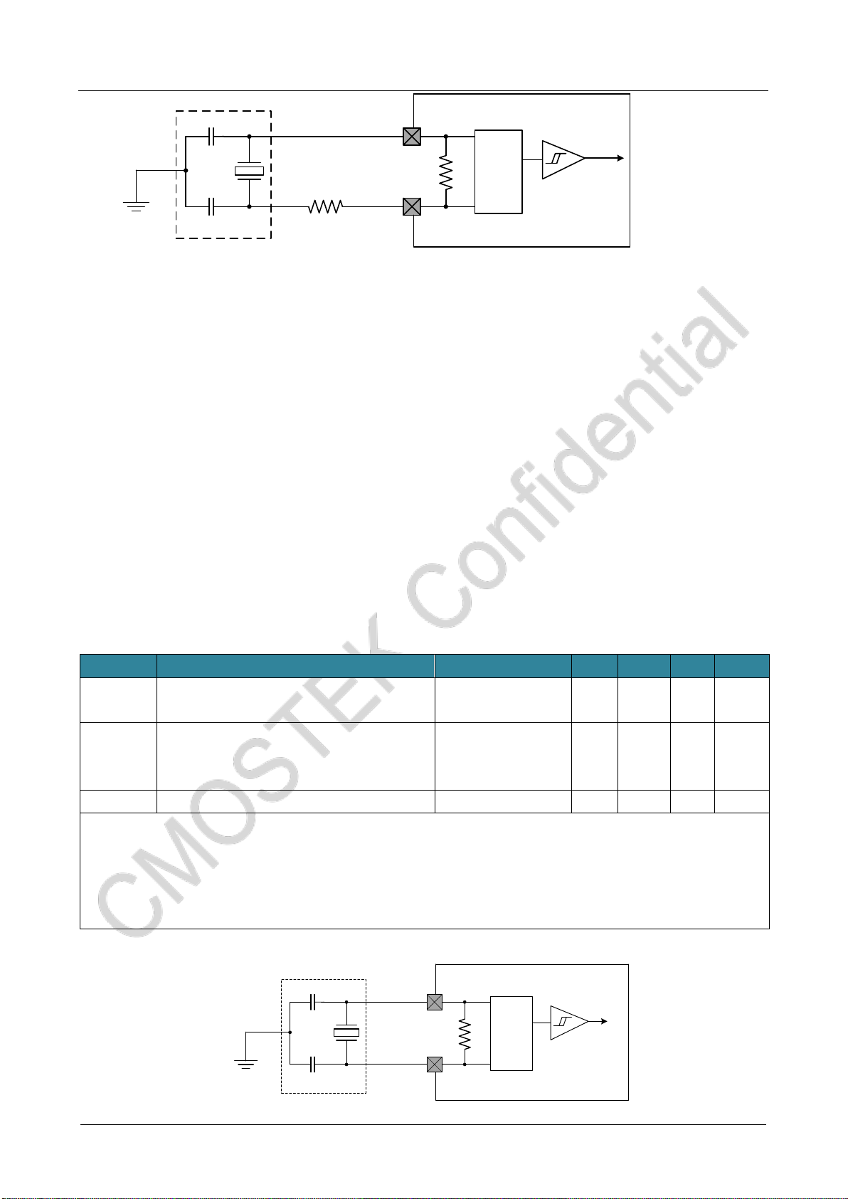
⚫A low-speed external clock generated by using a crystal / ceramic resonator
The low speed external clock (LSE) can be generated using an oscillator consisting of a 32.768 kHz crystal/ceramic oscillator.
The information given in this section is based on the use of typical external components listed in the table below. In
applications where the oscillator and load capacitance must be as close to the oscillator pin as possible to reduce output
distortion and stability time at startup. For detailed parameters of crystal oscillator (frequency, package, accuracy, etc.),
please consult the corresponding manufacturer (the crystal resonators mentioned here are usually referred to the passive
crystal oscillator).
Note: For CL1 and CL2, high quality porcelain dielectric capacitors between 5 p F and 15 p F and
well-compliant crystals or oscillators are recommended. Usually, CL1 and CL2 have the same parameters.
Crystal manufacturers usually give the parameters of the load capacitance as a serial combination of CL1 and
CL2.
Load capacitance CL is calculated by the following equation: CL = CL1 CL2 / (CL1 + CL2) + Cstray, where
Cstray is the capacitor of the pin and the capacitor associated with the PCB board or PCB.
LSE Oscillator Characteristic (fLSE=32.768 kHz)(1)
Symbol
Parameter
Condition
Min
Typ
Max
Unit
CL1
CL2(2)
Recommended load capacitance and corresponding
crystal serial impedance (RS)(3)
RS:30 KΩ~65 KΩ
-
-
20
pF
I2
LSE drive current
VDD=3.3 V
CL1=CL2=12.5 pF
RS= 30 KΩ
-
0.3
-
μA
tSU(LSE)(4)
Startup time
VDD is stable
-
2
-
s
1. Guaranteed by design and comprehensive assessment, not tested in production.
2. See the attention and warning paragraph above this table.
3. Choose high quality oscillator with a small RS value that can optimize current consumption. Check with the crystal
manufacturer for more details.
4. tSU(LSE)is the start time, measured from the software enabling LSE, until the stable 32.768 KHz oscillation is stabled.This value
is measured on a standard crystal oscillator, which may vary greatly by the crystal manufacturer.
CL2
CL1
32.768 kHz
Osillator Gain
control
Integrated
capacitance
oscillator
Typical applications of using 32.768 kHz crystals
CMT2380F64
www. cmostek.com
Rev 0.3 | 20 / 83
1.13 Controller internal clock source characteristics
⚫High speed internal (HSI) RC Oscillator
HSI Oscillator Characteristic(1)(2)
Sign
Parameter
Condition
Min
Typ
Max
Unit
HSI
Frequency
VDD=3.3 V,TA= 25 ℃,after calibration
7.92
8
8.08
MHz
ACCHSI
HSI oscillator
temperature drift
VDD=3.3 V,TA= -40~105 ℃,temperature
drift
-3
-
3
%
VDD=3.3 V,TA= - 10~85 ℃,temperature
drift
-2.5
-
2
%
VDD=3.3 V,TA= 0~70 ℃,temperature drift
-2
-
1.5
%
tSU(HSI)
HSI oscillator
startup time
1
-
3
μs
IDD(HSI)
HIS oscillator
power consumption
-
80
150
μA
1. Unless otherwise specified, VDD = 3.3 V,TA = -40~85 ℃.
2. Guaranteed by design and comprehensive assessment, not tested in production.
⚫Low speed internal (LSI) RC oscillator
LSI Oscillator Characteristic(1)
Sign
Parameter
Condition
Min
Typ
Max
Unit
fLSI(2)
output frequency
25℃calibration, VDD =3.3 V
29
30
31
KHz
VDD =1.8 V ~5.5 V,
TA = -40~105 ℃
24
30
36
KHz
tSU(LSI)
(3)
LSI oscillator start time
-
30
80
μs
IDD(LSI)
(3)
LSI oscillator power
consumption
-
0.2
-
μA
1. Unless otherwise specified, VDD = 3.3 V,TA = -40~85 ℃.
2. Guaranteed by design and comprehensive assessment, not tested in production.
1.14 Controller low-power mode wake-up time
The arousal times listed in the table below are measured during the arousal phase of an 8MHz HIS RC oscillator. The clock
source used on wake-up depends on the current mode of operation:
◼Stop or Sleep mode:the clock source is RC oscillator
◼Sleep mode:clock source is the clock used when entering into sleep mode
Wake-up time in the low-power mode
Symbol
Parameter
Typ
Unit
tWUSLEEP(1)
Awaken from sleep mode
16
HCLK(2)
tWUSTOP(1)
Awaken from stop mode
20
us
tWUPD(1)
Awaken from stanby mode
55
us
1. The awaken time counts from the beginning of the wake up event until the user program reads the first instruction;
2. HCLK is the AHB clock frequency.
f
Table of contents
Other CMOSTEK Transceiver manuals

CMOSTEK
CMOSTEK CMT2300A User manual

CMOSTEK
CMOSTEK CMT2300A User manual

CMOSTEK
CMOSTEK CMT2380F17 User manual

CMOSTEK
CMOSTEK CMT2300AW Instruction Manual

CMOSTEK
CMOSTEK CMT2310A User manual

CMOSTEK
CMOSTEK CMT2300A User manual

CMOSTEK
CMOSTEK CMT2300A Operating manual

CMOSTEK
CMOSTEK CMT216 Series User manual

CMOSTEK
CMOSTEK CMT2300A-EQR User manual


