CMOSTEK CMT2380F17 User manual

CMT2380F17
Rev0.1 | 1/347
www.cmostek.com
MCU Features
1-T 80C51 CPU platform
16kB program area Flash with password access
protects. Default space configuration:
-AP program space (13.5 kB, 0000h ~ 35FFh)
-IAP data space (1.0 kB, 3600h ~ 39FFh)
-ISP boot code space (1.5 kB, 3A00h ~ 3FFFh)
1 kB data memory
-256-byte high-speed buffer
-768-byte of extended RAM (XRAM)
-Extended RAM (XRAM) supporting page access
On-chip debug interface (OCD)
Multiple power control modes: power-down mode, idle
mode, slow-frequency mode, sub-frequency mode,
RTC mode, watch mode, and monitor mode
-All interrupts supporting to wake up the CPU
from IDLE mode
-10 interrupt sources supporting to wake up the
CPU in power-down mode
-Slow-frequency mode and sub-frequency mode
supporting low-speed MCU operation
-RTC mode supporting real-time clock (RTC) to
wake up the CPU in power-down mode
-Watch mode supporting watchdog (WDT) to
wake up the CPU in power-down mode
-Monitor mode supporting BOD1 to wake up the
CPU in power-down mode
Operating frequency range: up to 25 MHz
-External crystal oscillator mode, 0–12 MHz at
2.0–3.6 V and 0–25 MHz at 2.4–3.6 V
-CPU operating frequency can reach 12 MHz at
1.8-3.6 V and 25 MHz at 2.2-3.6 V
-When on-chip clock frequency multiplier (CKM)
is at 2.7–3.6 V, the CPU operating frequency
can reach 36 MHz.
Double data pointer
Interrupt control
-16 interrupt sources, 4 priority levels
-3 external interrupts nINT0/1/2, with filtering
-All external interrupts supporting high/low or
rising/falling edge triggering
8-channel 12-bit single-endedADC with a sampling
rate greater than 500 ksps
1master/slaveSPIserialinterface,the ratereaching 12MHz
2 master/slave two-wire serial interfaces: TWI0/I2C0
and STWI (SI2C)
1-channel DMA engine
-P2P, M2P, P2M
-Memory target: XRAM
-Peripheral targets: UART0, UART1, SPI,
TWI0/I2C0, ADC12 and CRC16
-Timer 5 and Timer 6 are applied by DMA; they
are independent timers when DMA is not
enabled.
Totally 9/11 timers/counters on-chip
-RTC timer and WDT timer
-Timer 0, 1, 2, 3
-PCA0, programmable counter array 0
-S0BRG and S1BRG
-When timer 2/3 is used in separated mode,
there are a total of 11 timers
8 keyboard interrupts
1 enhanced UART0 and 1 normal UART1
RF Features
Operating frequency: 127-1020 MHz
Modulation and demodulation methods: (G)FSK,
(G)MSK, OOK
Data rate: 0.5-300 kbps
Sensitivity: -121 dBm @ 434 MHz, FSK
Receive current: 8.5 mA@ 434 MHz, FSK
Transmitting current: 72 mA @ 20 dBm, 434 MHz
Configurable FIFO up to 64-Byte
System Features
Operating voltage: 1.8 –3.6 V
Operating temperature: -40 –85 ℃
QFN40 5x5 packaging
Application
Automatic meter reading
Home security and building automation
Wireless sensor networks and industrial monitoring
ISM band data communication
CMT2380F17
Ultra Low Power Sub-1GHz Wireless MCU
Copyright © By CMOSTEK
CMT2380F17
Rev0.1 | 2/347
www.cmostek.com
Description
Employed an 8-bit CPU core and an ultra-low power RF transceiver, the CMT2380F17 is a (G)FSK, (G)MSK, and OOK wireless
MCU with high performance and ultra-low power applying to 127 to 1020 MHz band wireless applications. Operating with 1.8 to
3.6 V supply voltage, the CMT2380F17 consumes only 72 mA transmission current and 8.5 mA (exclusive of MCU consuming)
receiving current while delivering up to 20 dBm power and reaching -121 dBm sensitivity.
The device employs a wide range of peripherals like support of standard UART, I2C and SPI interfaces, up to 25 general-purpose
I/Os, support of internal high-speed, low-speed, low-power RC oscillators and 32.768 kHz external crystal oscillators, flexible
data handling and packet handler, up to 64-byte Tx/Rx FIFO, feature-enriched RF GPIO, multiple low-power modes and fast-start
mechanisms, high-precision RSSI, manual fast frequency hopping, multi-channel input 12-bit high-speed ADC, etc. Leading the
industry in the aspect of the smallest package size, the CMT2380F17 is ideal for IoT applications with critical requests in size
constraints and power-efficiency.
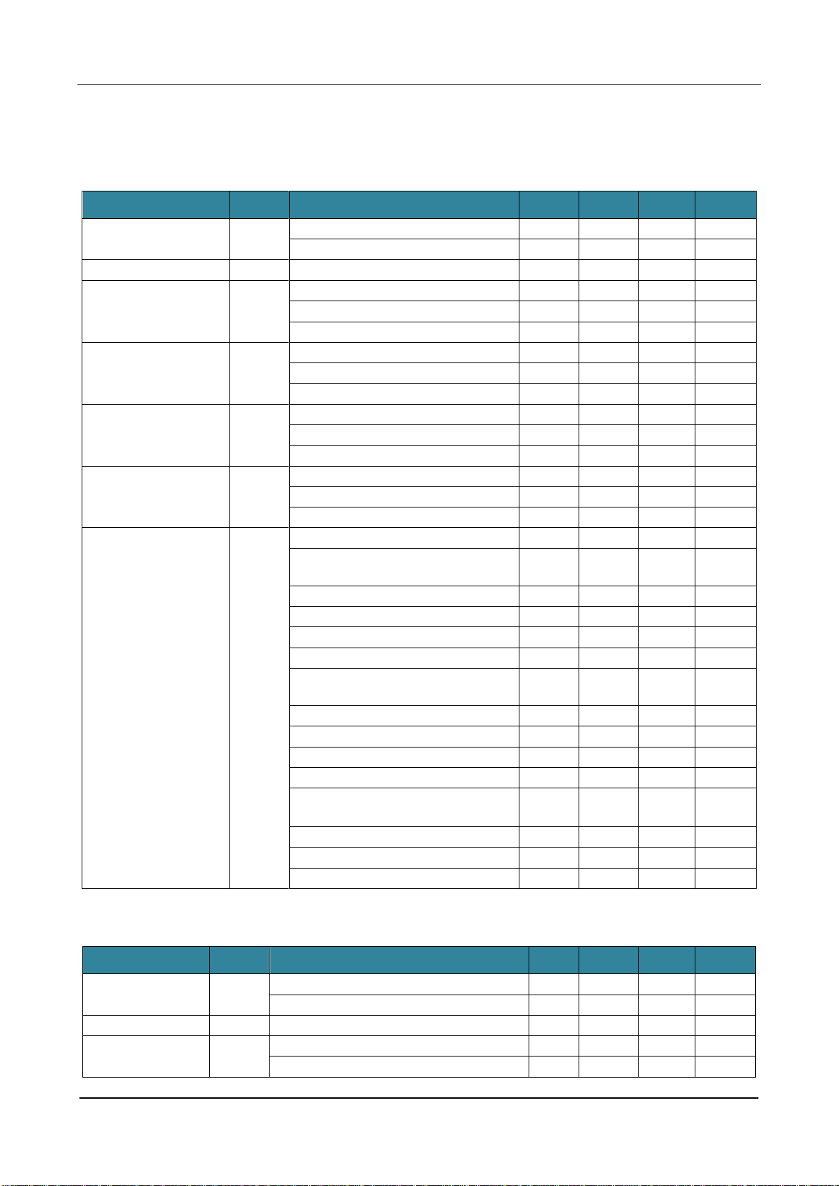
Table 1. The CMT2380F17 Resource List
Memory
Analog
Peripherals
Digital Peripherals
ROM
RAM
ADC
BOD
RTC
WDT
Timer
PCA
UART
SPI
TWI
KBI
GPIO
16K
1K
12bits x 8-ch
800ksps
√
1
1
16bits
x 4
6-chCapture/Compare///PWM
2-chCompare/PWM
2
1
2
8-ch
17
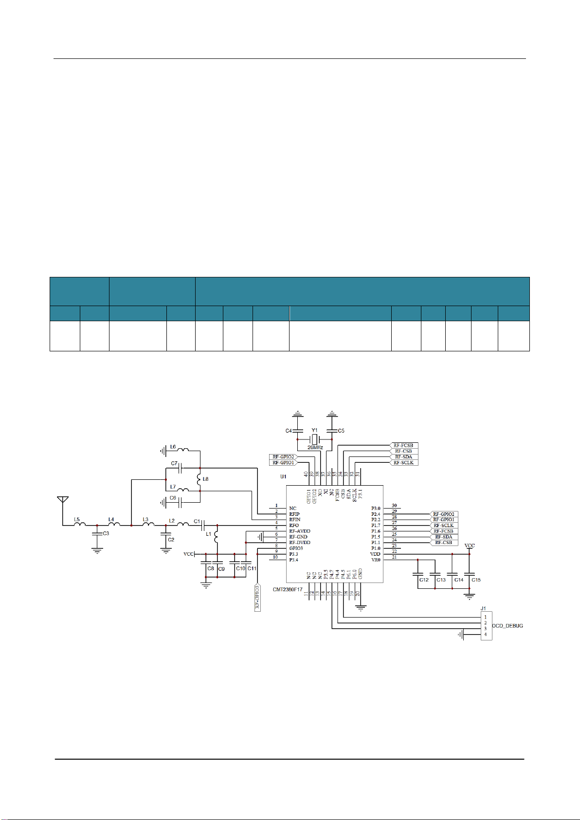
Figure 1. Typical Application Schematic for the CMT2380F17 (20dBm Output Power)

CMT2380F17
Rev0.1 | 3/347
www.cmostek.com
Table 2. Typical Application BOM (20dBm Output Power)
Label
Description
Component Value
Unit
Supplier
434 MHz
868MHz
915MHz
C1
±5%, 0402 NP0, 50 V
15
18
18
pF
-
C2
±5%, 0402 NP0, 50 V
3
3.6
3.6
pF
-
C3
±5%, 0402 NP0, 50 V
6.2
3.3
3.3
pF
-
C4
±5%, 0402 NP0, 50 V
24
24
24
pF
-
C5
±5%, 0402 NP0, 50 V
24
24
24
pF
-
C6
±5%, 0402 NP0, 50 V
4.7
2
1.8
pF
-
C7
±5%, 0402 NP0, 50 V
4.7
2
1.8
pF
-
C8
±20%, 0603 X7R, 25 V
4.7
uF
-
C9
±5%, 0402 NP0, 50 V
470
pF
-
C10
±20%, 0402 X7R, 25 V
0.1
uF
C11
±20%, 0402 X7R, 25 V
0.1
uF
C12
±20%, 0402 X7R, 25 V
0.1
uF
-
C13
±20%, 0603 X7R, 25 V
4.7
uF
-
C14
±20%, 0603 X7R, 25 V
1
uF
-
C15
±20%, 0603 X7R, 25 V
0.1
uF
-
L1
±10%, 0603 multilayer chip inductor
180
100
100
nH
Sunlord
SDCL
L2
±10%, 0603 multilayer chip inductor
22
12
12
nH
Sunlord
SDCL
L3
±10%, 0603 multilayer chip inductor
15pF
15
15
nH
Sunlord
SDCL
L4
±10%, 0603 multilayer chip inductor
33
6.2
6.2
nH
Sunlord
SDCL
L5
±10%, 0603 multilayer chip inductor
33
6.2
6.2
nH
Sunlord
SDCL
L6
±10%, 0603 multilayer chip inductor
27
15
15
nH
Sunlord
SDCL
L7
±10%, 0603 multilayer chip inductor
27
15
15
nH
Sunlord
SDCL
L8
±10%, 0603 multilayer chip inductor
68
12
12
nH
Sunlord
SDCL
Y1
±10 ppm, SMD32*25 mm
26
MHz
EPSON
U1
CMT2380F17, ultra-low power
sub-1GHz wireless MCU
-
-
CMOSTEK

CMT2380F17
Rev0.1 | 4/347
www.cmostek.com
Table of Content
MCU Features.................................................................................................................................................................... 1
RF Features ....................................................................................................................................................................... 1
System Features ............................................................................................................................................................... 1
Application......................................................................................................................................................................... 1
Description ........................................................................................................................................................................ 2
1Electrical Specifications ............................................................................................................................................11
1.1 Recommended Operating Conditions ................................................................................................................. 11
1.2 Absolute Maximum Ratings................................................................................................................................. 11
1.3 RF Power Consumption...................................................................................................................................... 12
1.4 Receiver.............................................................................................................................................................. 12
1.5 Transmitter.......................................................................................................................................................... 14
1.6 RF Operating Mode Switching Time ................................................................................................................... 15
1.7 RF Frequency Synthesizer.................................................................................................................................. 15
1.8 Requirement on Crystals for RF Section............................................................................................................. 17
1.9 Controller DC Specification................................................................................................................................. 17
1.10 Controller Power Consumption Characteristics................................................................................................... 18
1.11 BOD Characteristics............................................................................................................................................ 18
1.12 Controller IHRCO Characteristics ....................................................................................................................... 18
1.13 Controller ILRCO Characteristics........................................................................................................................ 19
1.14 Controller CKM Characteristics........................................................................................................................... 19
1.15 Controller Flash Characteristics.......................................................................................................................... 19
1.16 Controller ADC Characteristics ........................................................................................................................... 19
1.17 IVR Characteristics ............................................................................................................................................. 20
1.18 Controller Serial Port Timing Characteristics....................................................................................................... 21
1.19 Controller SPI Timing Characteristics ................................................................................................................. 21
1.20 Receive Current and Supply Voltage Correlation................................................................................................ 23
1.21 Correlation Among Receive Current, Supply Voltage and Temperature............................................................. 24
1.22 Receive Sensitivity and Supply Voltage Correlation............................................................................................ 25
1.23 Receive Sensitivity and Temperature Correlation............................................................................................... 25
1.24 Transmit Power and Supply Voltage Correlation................................................................................................. 26
1.25 Phase Noise........................................................................................................................................................ 27
2Pin Description.......................................................................................................................................................... 28
3Chip Structure............................................................................................................................................................ 32
4Sub-GHz Transceiver ................................................................................................................................................ 35
4.1 Transmitter.......................................................................................................................................................... 35
4.2 Receiver.............................................................................................................................................................. 35
4.3 Transceiver Power-on Reset (POR).................................................................................................................... 35
4.4 Transceiver Crystal Oscillator ............................................................................................................................. 36
4.5 Transceiver Built-in Low Frequency Oscillator (LPOSC)..................................................................................... 36
4.6 Transceiver Built-in Low Battery Detection.......................................................................................................... 37
4.7 Receiver Signal Strength Indication (RSSI) ........................................................................................................ 37
4.8 Phase Jump Detector (PJD)................................................................................................................................ 37
4.9 Receiver Clock Data Recovery (CDR) ................................................................................................................ 38
4.10 Fast Manual Frequency Hopping ........................................................................................................................ 39
4.11 Transceiver Control Interface and Operating Mode ............................................................................................ 39
4.11.1 Transceiver SPI Interface Timing ..........................................................................................................39
4.11.2 Transceiver FIFO Interface Timing........................................................................................................40
4.11.3 Transceiver Operating Status, Timing, and Power Consumption..........................................................41
4.11.4 Transceiver GPIO Function and Interrupt Mapping...............................................................................44
580C51 CPU Function Description............................................................................................................................. 47
5.1 CPU Register...................................................................................................................................................... 47
5.2 CPU Timing......................................................................................................................................................... 48
5.3 CPU Addressing Mode........................................................................................................................................ 49
5.3.1 Direct Addressing (DIR) ........................................................................................................................49

CMT2380F17
Rev0.1 | 5/347
www.cmostek.com
5.3.2 Indirect Addressing (IND)......................................................................................................................49
5.3.3 Register Instruction (REG)....................................................................................................................49
5.3.4 Register-Specific Instruction..................................................................................................................49
5.3.5 Immediate Constant (IMM)....................................................................................................................49
5.3.6 Index Addressing...................................................................................................................................49
6Memory Organization................................................................................................................................................ 50
6.1 On-Chip Program Flash ...................................................................................................................................... 50
6.2 On-Chip Data RAM ............................................................................................................................................. 51
6.3 On-chip Expanded RAM (XRAM)........................................................................................................................ 52
6.4 Off-Chip External Data Memory access.............................................................................................................. 52
6.5 Declaration Identifiers in a C51-Compiler............................................................................................................ 52
7XRAM Access ............................................................................................................................................................ 54
7.1 MOVX on 16-bit Address with dual DPTR........................................................................................................... 54
7.2 MOVX on 8-bit Address with XRPS .................................................................................................................... 55
8Direct Memory Access Controller (DMA)................................................................................................................. 57
8.1 DMA Structure..................................................................................................................................................... 57
8.2 DMA Operation ................................................................................................................................................... 58
8.2.1 DMA Transfer Types..............................................................................................................................58
8.2.2 DMA Transfer Mode ..............................................................................................................................59
8.2.3 Transfer Count & Address Pointer.........................................................................................................59
8.2.4 Start a DMATransfer.............................................................................................................................60
8.2.5 Suspend or Stop DMATransfer.............................................................................................................60
8.2.6 DMA Interrupt........................................................................................................................................60
8.2.7 DMA Loop Mode ...................................................................................................................................61
8.2.8 Error Handling in DMA..........................................................................................................................61
8.2.9 Data Copied to CRC16 .........................................................................................................................61
8.2.10 Timer 5 & Timer 6..................................................................................................................................61
8.3 DMA Register...................................................................................................................................................... 62
8.4 Timer5 Register................................................................................................................................................... 64
8.5 Timer 6 Register.................................................................................................................................................. 66
9System Clock............................................................................................................................................................. 68
9.1 Clock Structure.................................................................................................................................................... 68
9.2 Clock Source Switching ...................................................................................................................................... 69
9.3 On-chip CKM (PLL)............................................................................................................................................. 69
9.4 Wake-up clock from CKM.................................................................................................................................... 69
9.5 Clock Register..................................................................................................................................................... 70
10 Watch Dog Timer (WDT)............................................................................................................................................ 74
10.1 WDT Structure .................................................................................................................................................... 74
10.2 WDT During Idle.................................................................................................................................................. 74
10.3 WDT Register...................................................................................................................................................... 75
10.4 WDT Hardware Option........................................................................................................................................ 77
11 Real-Time-Clock (RTC)/System-Timer..................................................................................................................... 78
12 System Reset............................................................................................................................................................. 82
12.1 Reset Source ...................................................................................................................................................... 82
12.2 Power-On Reset (POR) ...................................................................................................................................... 82
Note: POF0 must be cleared by software...................................................................................................................... 83
12.3 External Reset..................................................................................................................................................... 83
12.4 Software Reset.................................................................................................................................................... 84
12.5 Brown-Out Reset................................................................................................................................................. 84
12.6 WDT Reset.......................................................................................................................................................... 85
12.7 Illegal Address Reset.......................................................................................................................................... 85
13 Power Management................................................................................................................................................... 86

CMT2380F17
Rev0.1 | 6/347
www.cmostek.com
13.1 Brown-Out Detector ............................................................................................................................................ 86
13.2 Power Saving Mode............................................................................................................................................ 86
13.2.1 Slow Mode ............................................................................................................................................86
13.2.2 Sub-Clock Mode....................................................................................................................................87
13.2.3 RTC Mode.............................................................................................................................................87
13.2.4 Watch Mode..........................................................................................................................................87
13.2.5 Monitor Mode........................................................................................................................................87
13.2.6 Idle Mode..............................................................................................................................................87
13.2.7 Power-down Mode................................................................................................................................88
13.2.8 Interrupt Recovery from Power-down....................................................................................................89
13.2.9 Reset Recovery from Power-down .......................................................................................................89
13.2.10 KBI wakeup Recovery from Power-down..............................................................................................89
13.3 Power Control Register....................................................................................................................................... 89
14 Configurable I/O Ports............................................................................................................................................... 93
14.1 IO Structure......................................................................................................................................................... 93
14.1.1 Port 3 Quasi-Bidirectional IO Structure .................................................................................................93
14.1.2 Port 3 Push-Pull Output Structure.........................................................................................................94
14.1.3 Port 3 Input-Only (High Impedance Input) Structure .............................................................................94
14.1.4 Port 3 Open-Drain Output Structure......................................................................................................94
14.1.5 General Analog Input Only Structure.....................................................................................................95
14.1.6 General Open-Drain Output with Pull-up Resistor Structure.................................................................95
14.1.7 General Open-Drain Output Structure...................................................................................................95
14.1.8 General Port Digital Input Configured ...................................................................................................96
14.1.9 General Push-Pull Output Structure......................................................................................................96
14.1.10 Port Pin Output Driving Strength Selection ...........................................................................................96
14.1.11 Port Pin Output Fast Driving Selection..................................................................................................96
14.2 I/O Port Register ................................................................................................................................................. 96
14.2.1 Port 1 Register......................................................................................................................................97
14.2.2 Port 2 Register......................................................................................................................................98
14.2.3 Port 3 Register......................................................................................................................................99
14.2.4 Port 4 Register....................................................................................................................................100
14.2.5 Port 6 Register....................................................................................................................................101
14.2.6 Port Output Driving Strength Control Register ....................................................................................101
14.2.7 Port Output Fast Driving Control Register...........................................................................................103
14.3 Port Function Redirection.................................................................................................................................. 104
15 Interrupt.....................................................................................................................................................................112
15.1 Interrupt Structure............................................................................................................................................. 112
15.2 Interrupt Source ................................................................................................................................................ 114
15.3 Interrupt Enable................................................................................................................................................. 117
15.4 Interrupt Priority................................................................................................................................................. 117
15.5 Interrupt Process............................................................................................................................................... 118
15.6 nINTx Input Source Selection and input filter (x=0~2)....................................................................................... 119
15.7 Interrupt Register .............................................................................................................................................. 120
16 Timers/Counters...................................................................................................................................................... 130
16.1 Timer 0 and Timer 1.......................................................................................................................................... 130
16.1.1 Timer 0/1 Mode 0................................................................................................................................130
16.1.2 Timer 0/1 Mode 1................................................................................................................................132
16.1.3 Timer 0/1 Mode 2................................................................................................................................133
16.1.4 Timer 0/1 Mode 3................................................................................................................................134
16.1.5 Timer 0/1 Programmable Clock-Out....................................................................................................134
16.1.6 Timer 0/1 Register...............................................................................................................................136
16.2 Timer 2.............................................................................................................................................................. 141

CMT2380F17
Rev0.1 | 7/347
www.cmostek.com
16.2.1 Timer 2 Mode 0 (Auto-Reload and External Interrupt) ........................................................................141
16.2.2 Timer 2 Mode 1 (Auto-Reload with External Interrupt)........................................................................142
16.2.3 Timer 2 Mode 2 (Capture)...................................................................................................................143
16.2.4 Timer 2 Mode 3 (Capture withAuto-Zero)...........................................................................................144
16.2.5 Split Timer 2 Mode 0 (AR and Ex. INT) ...............................................................................................145
16.2.6 Split Timer 2 Mode 1 (AR with Ex. INT)...............................................................................................146
16.2.7 Split Timer 2 Mode 2 (Capture)...........................................................................................................147
16.2.8 Split Timer 2 Mode 3 (Capture with Auto-Zero)...................................................................................148
16.2.9 Split Timer 2 Mode 4 (8-bit PWM Mode) .............................................................................................149
16.2.10 Baud-Rate Generator Mode (BRG).....................................................................................................149
16.2.11 Timer 2 Programmable Clock Output..................................................................................................151
16.2.12 Timer 2 Register..................................................................................................................................153
16.3 Timer 3.............................................................................................................................................................. 157
16.3.1 Timer 3 Mode 0 (Auto-Reload and External Interrupt) ........................................................................157
16.3.2 Timer 3 Mode 1 (Auto-Reload with External Interrupt)........................................................................157
16.3.3 Timer 3 Mode 2 (Capture)...................................................................................................................158
16.3.4 Timer 3 Mode 3 (Capture andAuto-Zero) ...........................................................................................159
16.3.5 Split Timer 3 Mode 0 (Auto-Reload and External Interrupt).................................................................159
16.3.6 Split Timer 3 Mode 1 (Auto-Reload with External Interrupt) ................................................................160
16.3.7 Split Timer 3 Mode 2 (Capture)...........................................................................................................162
16.3.8 Split Timer 3 Mode 3 (Capture with Auto-Zero)...................................................................................163
16.3.9 Split Timer 3 Mode 4 (8-bit PWM Mode) .............................................................................................164
16.3.10 Timer 3 Programmable Clock Output..................................................................................................164
16.3.11 Timer 3 Register..................................................................................................................................166
16.4 Timer Global Control......................................................................................................................................... 170
16.4.1 Global Enable for all Timer Run ..........................................................................................................170
16.4.2 Global Control for all Timer Reload.....................................................................................................171
16.4.3 Global Control for all Timer Stop .........................................................................................................172
17 Programmable Counter Array (PCA0).................................................................................................................... 173
17.1 PCA Overview................................................................................................................................................... 173
17.2 PCA Timer/Counter........................................................................................................................................... 173
17.3 Compare/Capture Modules............................................................................................................................... 179
17.4 Operation Modes of the PCA ............................................................................................................................ 182
17.4.1 Capture Mode .....................................................................................................................................183
17.4.2 Buffered Capture Mode.......................................................................................................................183
17.4.3 16-bit Software Timer Mode (Compare mode)....................................................................................185
17.4.4 High Speed Output Mode (Compare Output mode)............................................................................185
17.4.5 Buffered 8-bit PWM Mode...................................................................................................................185
17.4.6 Un-buffered 10/12/16-bit PWM Mode .................................................................................................186
17.4.7 Buffered 10/12/16-bit PWM Mode ......................................................................................................187
17.4.8 COPM Mode .......................................................................................................................................188
17.4.9 Buffered COPM Mode............................................................................................................................189
17.4.10 FIFO Data Mode .................................................................................................................................190
17.4.11 Enhanced PWM Control......................................................................................................................190
17.4.12 PCA Module Output Control................................................................................................................194
17.4.13 Variable Resolution on Central Aligned PWM .....................................................................................198
18 Serial Port 0 (UART0) .............................................................................................................................................. 200
18.1 Serial Port 0 Mode 0 ......................................................................................................................................... 201
18.2 Serial Port 0 Mode 1 ......................................................................................................................................... 202
18.3 Serial Port 0 Mode 2 and Mode 3...................................................................................................................... 203
18.4 Frame Error Detection....................................................................................................................................... 204
18.5 Multiprocessor Communications....................................................................................................................... 204

CMT2380F17
Rev0.1 | 8/347
www.cmostek.com
18.6 Automatic Address Recognition........................................................................................................................ 204
18.7 Baud Rate Setting............................................................................................................................................. 206
18.7.1 Baud Rate Selection in S0 ...............................................................................................................206
18.7.2 Baud Rate in Mode 0 ..........................................................................................................................206
18.7.3 Baud Rate in Mode 2 ..........................................................................................................................207
18.7.4 Baud Rate in Mode 1 & 3....................................................................................................................208
18.7.4.1 Using Timer 1 as the Baud Rate Generator........................................................................................208
18.7.4.2 Using Timer 2 as the Baud Rate Generator........................................................................................215
18.7.4.3 Using S0 Baud Rate Timer as the Baud Rate Generator (S0BRG) ....................................................220
18.7.4.4 Using S1 Baud Rate Timer as the Baud Rate Generator....................................................................221
18.8 Serial Port 0 Mode 4 (SPI Master) .................................................................................................................... 221
18.9 Serial Port 0 Register........................................................................................................................................ 223
18.10 Serial Port 0 Enhance function........................................................................................................... 226
18.10.1 S0 Baud Rate Generator (S0BRG).....................................................................................................228
18.10.2 Independent Baud Rate Generator S0BRG for S0 .............................................................................228
18.10.3 S0 Enhanced Mode.............................................................................................................................229
18.10.4 S0 LIN Bus Register............................................................................................................................229
18.10.5 S0 acts as 8-bit Timer Mode ...............................................................................................................230
18.10.6 S0 acts as 16-bit Timer Mode..............................................................................................................230
18.10.7 S0BRG Programmable Clock Output..................................................................................................231
19 Serial Port 1 (UART1) .............................................................................................................................................. 232
19.1 Serial Port 1 Baud Rate Generator (S1BRG).................................................................................................... 232
19.2 S1BRG configuration (S1TME=0)..................................................................................................................... 232
19.2.1 Baud Rate in Mode 0 ..........................................................................................................................232
19.2.2 Baud Rate in Mode 2 ..........................................................................................................................233
19.2.3 Baud Rate in Mode 1 & 3....................................................................................................................233
19.3 Serial Port 1 Mode 4 (SPI Master) .................................................................................................................... 236
19.4 8-Bit Timer Mode on S1BRG............................................................................................................................. 238
19.5 16-Bit Timer Mode on S1BRG........................................................................................................................... 240
19.6 S1BRT Programmable Clock Output ................................................................................................................ 240
How to Program 8-bit S1BRG in Clock-out Mode....................................................................................................... 241
19.7 S1 Baud Rate Generator for S0........................................................................................................................ 242
19.8 Serial Port 1 Register........................................................................................................................................ 242
20 Serial Peripheral Interface (SPI)............................................................................................................................. 247
20.1 Typical SPI Configurations................................................................................................................................ 248
20.1.1 Single Master & Single Slave..............................................................................................................248
20.1.2 Dual Device, where either can be a Master or a Slave .......................................................................248
20.1.3 Single Master & Multiple Slaves..........................................................................................................248
20.2 Configuring the SPI........................................................................................................................................... 249
20.2.1 Additional Considerations for a Slave .................................................................................................250
20.2.2 Additional Considerations for a Master ...............................................................................................250
20.2.3 Mode Change on nSS-pin...................................................................................................................250
20.2.4 Transmit Holding Register Full Flag....................................................................................................250
20.2.5 Write Collision.....................................................................................................................................250
20.2.6 SPI Clock Rate Select.........................................................................................................................251
20.3 Data Mode......................................................................................................................................................... 252
20.4 Daisy-Chain Connection ................................................................................................................................... 254
20.4.1 Configuring the Daisy-Chain...............................................................................................................254
20.5 SPI Register...................................................................................................................................................... 254
21 Two Wire serial Interface (TWI0/ I2C0)................................................................................................................... 258
21.1 Operating Modes............................................................................................................................................... 258
21.1.1 Master Transmitter Mode....................................................................................................................259
21.1.2 Master Receiver Mode........................................................................................................................260

CMT2380F17
Rev0.1 | 9/347
www.cmostek.com
21.1.3 Slave Transmitter Mode......................................................................................................................260
21.1.4 Slave Receiver Mode..........................................................................................................................261
21.2 Miscellaneous States........................................................................................................................................ 261
21.3 Using the TWI/ I2C............................................................................................................................................ 262
The figure below shows how to read the flow charts. ............................................................................................... 262
21.4 TWI0/ I2C0 Register.......................................................................................................................................... 268
22 Serial Interface Detection (STWI/SI2C) .................................................................................................................. 272
22.1 SID Structure..................................................................................................................................................... 272
22.2 SID Register...................................................................................................................................................... 272
23 Beeper ...................................................................................................................................................................... 274
24 Keypad Interrupt (KBI) ............................................................................................................................................ 276
24.1 KBI Structure..................................................................................................................................................... 276
24.2 KBI Register...................................................................................................................................................... 276
25 General Purpose Logic (GPL-CRC)........................................................................................................................ 279
25.1 GPL-CRC Structure .......................................................................................................................................... 279
25.2 GPL-BOREV Structure...................................................................................................................................... 280
25.3 GPL Register..................................................................................................................................................... 280
26 12-Bit ADC................................................................................................................................................................ 282
26.1 ADC Structure................................................................................................................................................... 282
26.2 ADC Operation.................................................................................................................................................. 283
26.2.1 ADC Input Channels ...........................................................................................................................283
26.2.2 ADC Internal Voltage Reference.........................................................................................................283
26.2.3 Starting a Conversion..........................................................................................................................283
26.2.4 ADC Conversion Rate.........................................................................................................................284
26.2.5 ADC Interrupts ....................................................................................................................................284
26.2.6 ADC Window Detect ...........................................................................................................................285
26.2.7 ADC Channel Scan Mode...................................................................................................................286
26.2.8 Transfer ADC Data by DMA ................................................................................................................286
26.2.9 I/O Pins Used with ADC Function........................................................................................................287
26.2.10 Idle and Power-Down Mode................................................................................................................287
26.2.11 How to improve ADC Accuracy ...........................................................................................................287
26.3 ADC Register.................................................................................................................................................... 288
27 Internal Voltage Reference (IVR, 1.4V) .............................................................................................................. 296
27.1 IVR (1.4V) Structure.......................................................................................................................................... 296
27.2 IVR Register...................................................................................................................................................... 296
27.3 How to read IVR (1.4V) ADC Prestored value................................................................................................... 296
28 ISP and IAP .............................................................................................................................................................. 298
28.1 CMT2380F17 Flash Memory Configuration ...................................................................................................... 298
28.2 CMT2380F17 Flash Access in ISP/IAP............................................................................................................. 298
28.2.1 ISP/IAP Flash Page Erase Mode........................................................................................................299
28.2.2 ISP/IAP Flash Byte Program Mode.....................................................................................................301
28.2.3 ISP/IAP Flash Read Mode ..................................................................................................................303
28.3 ISP Operation.................................................................................................................................................... 304
28.3.1 Hardware approached ISP..................................................................................................................304
28.3.2 Software approached ISP...................................................................................................................305
28.3.3 Notes for ISP.......................................................................................................................................305
28.4 In-Application-Programming (IAP)..................................................................................................................... 306
28.4.1 IAP-memory Boundary/Range ............................................................................................................306
28.4.2 Update data in IAP-memory................................................................................................................306
28.4.3 Notes for IAP.......................................................................................................................................307
28.5 ISP/IAP Register............................................................................................................................................... 307

CMT2380F17
Rev0.1 | 10/347
www.cmostek.com
28.6 ISP/IAP Sample Code....................................................................................................................................... 310
29 Page P SFR Access................................................................................................................................................. 312
30 Auxiliary SFRs ......................................................................................................................................................... 317
30.1 SFR Figure(Page 0~F)................................................................................................................................. 317
30.2 SFR Bit Assignment (Page 0~F)....................................................................................................................... 318
30.3 Auxiliary SFR Map (Page P) ............................................................................................................................. 322
30.4 Auxiliary SFR Bit Assignment (Page P) ............................................................................................................ 322
30.5 Auxiliary SFR Register...................................................................................................................................... 324
31 Hardware Option...................................................................................................................................................... 333
32 Application Notes.................................................................................................................................................... 335
32.1 Power Supply Circuit......................................................................................................................................... 335
32.2 Reset Circuit...................................................................................................................................................... 335
32.3 ICP and OCD Interface Circuit.......................................................................................................................... 335
32.4 In-Chip-Programming Function......................................................................................................................... 336
32.5 On-Chip-Debug Function .................................................................................................................................. 337
33 Instruction Set ......................................................................................................................................................... 339
34 Ordering Information............................................................................................................................................... 342
35 Packaging Information............................................................................................................................................ 343
36 Top Marking ............................................................................................................................................................. 344
37 Reference Documents............................................................................................................................................. 345
38 Revise History.......................................................................................................................................................... 346
39 Contacts ................................................................................................................................................................... 347

CMT2380F17
Rev0.1 | 11/347
www.cmostek.com
1 Electrical Specifications
VDD= 3.3 V,TOP= 25 °C,FRF = 433.92 MHz, sensitivity is measured by receiving a PN9 sequence and matching to 50 Ω
impedance, 0.1% BER if nothing else stated. All measurement results are obtained using the evaluation board CMT2380F17-EM
if nothing else stated.。
1.1 Recommended Operating Conditions
Parameter
Symbol
Condition
Min.
Typ.
Max.
Unit
Operating supply voltage
VDD-RF
1.8
3.6
V
VOP3-MCU
CPU operating speed 0-36MHz
2.7
3.6
V
VOP4-MCU
CPU operating speed 0-24MHz
2.2
3.6
V
VOP5-MCU
CPU operating speed 0-12MHz
1.8
3.6
V
Operating temperature
TOP
-40
85
℃
RF supply voltage slope
VRF-PSR
1
mV/us
Controller supply voltage Slope
VMCU-PSR
50
mV/us
Controller power-on reset
effective voltage
VMCU-POR
0.1
V
1.2 Absolute Maximum Ratings
Parameter
Symbol
Condition
Min.
Typ.
Max.
Supply voltage
VDD
-0.3
3.6
V
Interface voltage
VIN
-0.3
3.6
V
Junction temperature
TJ
-40
125
℃
Storage temperature
TSTG
-50
150
℃
Soldering temperature
TSDR
Lasts for at least 30 seconds
255
℃
ESD rating[2]
Human body model (HBM)
-2
2
kV
Latch-up current
@ 85 ℃
-100
100
mA
Maximum current from
MCU-VDD to ground
200
mA
Maximum sink current of any
pin of MCU
40
mA
Notes:
[1]. Exceeding the Absolute Maximum Ratings may cause permanent damage to the equipment. This value is a pressure rating
and does not imply that the function of the equipment is affected under this pressure condition, but if it is exposed to
absolute maximum ratings for extended periods of time, it may affect equipment reliability.
[2]. The CMT2380F17 is a high performance RF integrated circuit. The operation and assembly of this chip should only be
performed on a workbench with good ESD protection.
Caution! ESD sensitive device. Precaution should be used when handling the device in order to
prevent performance degradation or loss of functionality.
CMT2380F17
Rev0.1 | 12/347
www.cmostek.com
1.3 RF Power Consumption
Parameter
Symbol
Condition
Min.
Typ.
Max.
Unit
Sleep current
ISLEEP
Sleep mode, sleep counter off
300
nA
Sleep mode ,sleep counter on
800
nA
Standby current
IStandby
Crystal oscillator on
1.45
mA
RFS current
IRFS
433 MHz
5.7
mA
868 MHz
5.8
mA
915 MHz
5.8
mA
TFS current
ITFS
433 MHz
5.6
mA
868 MHz
5.9
mA
915 MHz
5.9
mA
RX current
(high performance)
IRx-HP
FSK, 433 MHz, 10 kbps,10 kHz FDEV
8.5
mA
FSK, 868 MHz, 10 kbps, 10 kHz FDEV
8.6
mA
FSK, 915 MHz, 10 kbps,10 kHz FDEV
8.9
mA
RX current
(low power mode)
IRx-LP
FSK, 433 MHz, 10 kbps, 10 kHz FDEV
7.2
mA
FSK, 868 MHz, 10 kbps, 10 kHz FDEV
7.3
mA
FSK, 915 MHz, 10 kbps, 10 kHz FDEV
7.6
mA
TX current
ITx
FSK,433 MHz, +20 dBm (Direct-tie)
72
mA
FSK, 433 MHz, +20 dBm (With RF
switch)
77
mA
FSK, 433 MHz, +13 dBm (Direct-tie)
23
mA
FSK, 433 MHz, +10 dBm (Direct-tie)
18
mA
FSK, 433 MHz, -10 dBm (Direct-tie)
8
mA
FSK, 868 MHz, +20dBm (Direct-tie)
87
mA
FSK, 868 MHz, +20dBm (With RF
switch)
80
mA
FSK, 868 MHz, +13 dBm (Direct-tie)
27
mA
FSK, 868 MHz, +10 dBm (Direct-tie)
19
mA
FSK, 868 MHz, -10 dBm (Direct-tie)
8
mA
FSK, 915 MHz, +20 dBm (Direct-tie)
70
mA
FSK, 915 MHz, +20 dBm (With RF
switch)
75
mA
FSK, 915 MHz, +13 dBm(Direct-tie)
28
mA
FSK, 915 MHz, +10 dBm (Direct-tie)
19
mA
FSK, 915 MHz, -10 dBm (Direct-tie)
8
mA
1.4 Receiver
Parameter
Symbol
Condition
Min.
Typ.
Max.
Unit
Data Rate
DR
OOK
0.5
40
kbps
FSK 和GFSK
0.5
300
kbps
Error
FDEV
FSK 和GFSK
2
200
kHz
Sensitivity
@ 433 MHz
S433-HP
DR = 2.0 kbps, FDEV = 10 kHz
-121
dBm
DR = 10 kbps, FDEV = 10 kHz
-116
dBm

CMT2380F17
Rev0.1 | 13/347
www.cmostek.com
Parameter
Symbol
Condition
Min.
Typ.
Max.
Unit
DR = 10 kbps, FDEV = 10 kHz(low-power
configuration)
-115
dBm
DR = 20 kbps, FDEV = 20 kHz
-113
dBm
DR = 20 kbps, FDEV = 20 kHz (low-power
configuration)
-112
dBm
DR = 50 kbps, FDEV = 25 kHz
-111
dBm
DR =100 kbps, FDEV = 50 kHz
-108
dBm
DR =200 kbps, FDEV = 100 kHz
-105
dBm
DR =300 kbps, FDEV = 100 kHz
--103
dBm
Sensitivity
@ 868 MHz
S868-HP
DR = 2.0 kbps, FDEV = 10 kHz
-119
dBm
DR = 10 kbps, FDEV = 10 kHz
-113
dBm
DR = 10 kbps, FDEV = 10 kHz(low-power
configuration)
-111
dBm
DR = 20 kbps, FDEV = 20 kHz
-111
dBm
DR = 20 kbps, FDEV = 20 kHz (low-power
configuration)
-109
dBm
DR = 50 kbps, FDEV = 25 kHz
-108
dBm
DR =100 kbps, FDEV = 50 kHz
-105
dBm
DR =200 kbps, FDEV = 100 kHz
-102
dBm
DR =300 kbps, FDEV = 100 kHz
-99
dBm
Sensitivity
@ 915 MHz
S915-HP
DR = 2.0 kbps, FDEV = 10 kHz
-117
dBm
DR = 10 kbps, FDEV = 10 kHz
-113
dBm
DR = 10 kbps, FDEV = 10 kHz(low-power
configuration)
-111
dBm
DR = 20 kbps, FDEV = 20 kHz
-111
dBm
DR = 20 kbps, FDEV = 20 kHz (low-power
configuration)
-109
dBm
DR = 50 kbps, FDEV = 25 kHz
-109
dBm
DR =100 kbps, FDEV = 50 kHz
-105
dBm
DR =200 kbps, FDEV = 100 kHz
-102
dBm
DR =300 kbps, FDEV = 100 kHz
--99
dBm
Saturation
PLVL
20
dBm
Image rejection ratio
IMR
FRF=433 MHz
35
dBc
FRF=868 MHz
33
dBc
FRF=915 MHz
33
dBc
Receive channel
bandwidth
BW
Receive channel bandwidth
50
500
kHz
Co-channel rejection
CCR
DR = 10 kbps, FDEV = 10 kHz
Interference with the same modulation
-7
dBc
Adjacent channel
rejection
ACR-I
DR = 10 kbps, FDEV = 10 kHz, BW = 100 kHz,
200 kHz channel spacing, interference with
the same modulation
30
dBc
Alternate channel
rejection
ACR-II
DR = 10 kbps, FDEV = 10 kHz, BW=100kHz,
400 kHz channel spacing, interference with
the same modulation
45
dBc
Blocking
BI
DR = 10 kbps, FDEV = 10 kHz, ±1 MHz offset,
continuous wave interference
70
dBc
DR = 10 kbps, FDEV = 10 kHz, ±2 MHz offset,
72
dBc
CMT2380F17
Rev0.1 | 14/347
www.cmostek.com
Parameter
Symbol
Condition
Min.
Typ.
Max.
Unit
continuous wave interference
DR = 10 kbps, FDEV = 10 kHz, ±10 MHz offset,
continuous wave interference
75
dBc
Input 3rd order
intercept point
IIP3
DR = 10 kbps, FDEV = 10 kHz, 1 MHz and
20 MHz offset two tone test, maximum system
gain setting
-25
dBm
RSSI range
RSSI
-120
20
dBm
More sensitivity
(typical
configuration)
433.92 MHz, DR = 1.2kbps, FDEV = 5 kHz
-122.9
dBm
433.92 MHz, DR = 1.2kbps, FDEV = 10 kHz
-121.8
dBm
433.92 MHz, DR = 1.2kbps, FDEV = 20 kHz
-119.5
dBm
433.92 MHz, DR = 2.4kbps, FDEV = 5 kHz
-120.6
dBm
433.92 MHz, DR = 2.4kbps, FDEV = 10 kHz
-120.3
dBm
433.92 MHz, DR = 2.4kbps, FDEV = 20 kHz
-119.7
dBm
433.92 MHz, DR = 9.6 kbps, FDEV = 9.6 kHz
-116.0
dBm
433.92 MHz, DR = 9.6 kbps, FDEV = 19.2 kHz
-116.1
dBm
433.92 MHz, DR = 20 kbps, FDEV = 10 kHz
-114.2
dBm
433.92 MHz, DR = 20 kbps, FDEV = 20 kHz
-113.0
dBm
433.92 MHz, DR = 50 kbps, FDEV = 25 kHz
-110.6
dBm
433.92 MHz, DR = 50 kbps, FDEV = 50 kHz
-109.0
dBm
433.92 MHz, DR = 100 kbps, FDEV = 50 kHz
-107.8
dBm
433.92 MHz, DR = 200 kbps, FDEV = 50 kHz
-103.5
dBm
433.92 MHz, DR = 200 kbps, FDEV = 100 kHz
-104.3
dBm
433.92 MHz, DR = 300 kbps, FDEV = 50 kHz
-98.0
dBm
433.92 MHz, DR = 300 kbps, FDEV = 150 kHz
-101.6
dBm
1.5 Transmitter
Parameter
Symbol
Condition
Min.
Typ.
Max.
Unit
Output power
POUT
Specific matching network is required for
different frequency bands
-20
+20
dBm
Output power step
PSTEP
1
dB
GFSK (Gaussian filter
coefficient)
BT
0.3
0.5
1.0
-
Output power change
with different
temperature
POUT-TOP
Temperature range:-40 to + 85 C
1
dB
Spurious emissions
POUT = +13 dBm,433MHz, FRF<1 GHz
-54
dBm
1 GHz to12.75 GHz, including
harmonics
-36
dBm
Harmonic output[1]
for FRF= 433 MHz
H2433
2nd harmonic,+20 dBm POUT
-46
dBm
H3433
3nd harmonic,+20 dBm POUT
-50
dBm
Harmonic output[1]
for FRF= 868 MHz
H2868
2nd harmonic,+20 dBm POUT
-43
dBm
H3868
3nd harmonic,+20 dBm POUT
-52
dBm
Harmonic output[1]
for FRF= 915 MHz
H2915
2nd harmonic,+20 dBm POUT
-48
dBm
H3915
3nd harmonic,+20 dBm POUT
-53
dBm
Harmonic output[1]
for FRF= 433 MHz
H2433
2nd harmonic,+13 dBm POUT
-52
dBm
H3433
3nd harmonic,+13 dBm POUT
-52
dBm

CMT2380F17
Rev0.1 | 15/347
www.cmostek.com
Parameter
Symbol
Condition
Min.
Typ.
Max.
Unit
Harmonic output[1]
for FRF= 868 MHz
H2868
2nd harmonic,+13 dBm POUT
-52
dBm
H3868
3nd harmonic,+13 dBm POUT
-52
dBm
Harmonic output[1]
for FRF= 915 MHz
H2915
2nd harmonic,+13 dBm POUT
-52
dBm
H3915
3nd harmonic,+13 dBm POUT
-52
dBm
Notes:
[1] The harmonic level mainly depends on the matching network. Above parameters are measured based on the
CMT2380F17-EM, users may get different results on their PCB designs.
1.6 RF Operating Mode Switching Time
Parameter
Symbol
Condition
Min.
Typ.
Max.
Units
Stabilizing time
TSLP-RX
From sleep to RX
1000
us
TSLP-TX
From sleep to TX
1000
us
TSTB-RX
From standby to RX
350
us
TSTB-TX
From standby to TX
350
us
TRFS-RX
From RFS to RX
20
us
TTFS-RX
From TFS to TX
20
us
TTX-RX
From TX to RX
(Needs 2Tsymbol to ramp down)
2Tsymbol
+350
us
TRX-TX
From RX to TX
350
us
Notes:
[1] TSLP-RX and TSLP-TX are dominated by the crystal oscillator startup time, and the start-up time is to a large degree crystal
dependent.
1.7 RF Frequency Synthesizer
Parameter
Symbol
Condition
Min.
Typ.
Max.
Unit
Frequency range
FRF
Need different matching networks.
760
1020
MHz
380
510
MHz
190
340
MHz
127
170
MHz
Frequency resolution
FRES
25
Hz
Frequency tuning time
tTUNE
150
us
Phase noise @ 433
MHz
PN433
10 kHz deviation
-94
dBc/Hz
100 kHz deviation
-99
dBc/Hz
500 kHz deviation
-118
dBc/Hz
1MHz deviation
-127
dBc/Hz
10 MHz deviation
-134
dBc/Hz
Phase noise @ 868
MHz
PN868
10 kHz deviation
-92
dBc/Hz
100 kHz deviation
-95
dBc/Hz
500 kHz deviation
-114
dBc/Hz
1MHz deviation
-121
dBc/Hz
10 MHz deviation
-130
dBc/Hz
Phase noise @ 915
MHz
PN915
10 kHz deviation
-89
dBc/Hz
100 kHz deviation
-92
dBc/Hz

CMT2380F17
Rev0.1 | 16/347
www.cmostek.com
Parameter
Symbol
Condition
Min.
Typ.
Max.
Unit
500 kHz deviation
-111
dBc/Hz
1MHz deviation
-121
dBc/Hz
10 MHz deviation
-130
dBc/Hz
CMT2380F17
Rev0.1 | 17/347
www.cmostek.com
1.8 Requirement on Crystals for RF Section
Parameter
Symbol
Condition
Min.
Typ.
Max.
Unit
Crystal frequency[1]
FXTAL
26
MHz
Crystal frequency
tolerance[2]
ppm
20
ppm
Load capacitance
CLOAD
15
pF
ESR
Rm
60
Ω
Crystal startup time[3]
tXTAL
400
us
Notes:
[1]. An external reference clock can be used to drive the
XI pin directly through a coupling capacitor if such a clock is available. The peak-to-peak level of the external reference
clock is required between 0.3 and 0.7 V.
[2]. It involves:(1) initial tolerance, (2) crystal loading, (3)
aging, and (4) temperature changing. The acceptable crystal frequency tolerance is subject to the bandwidth of the
receiver and the RF tolerance between the receiver and its paired transmitter.
[3]. This parameter is to a large degree crystal dependent.
1.9 Controller DC Specification
Parameter
Symbol
Condition
Min.
Typ.
Max.
Unit
Input high level (all IO ports)
VIH1
Except P6.0 and P6.1.
0.6
VDD
Input high level (RST, P6.0, P6.1)
VIH2
0.75
VDD
Input low level (all IO ports)
VIL1
Except P6.0 and P6.1.
0.15
VDD
Input low level (RST, P6.0, P6.1)
VIL2
0.2
VDD
Input high leakage current (all IO
ports)
IIH
VPIN = VDD
0
±1
uA
Logic 0 input current (P3 is in
quasi-bidirectional port mode or
input port with on-chip pull-up
resistor)
IIL1
VPIN = 0.4V
-20
-30
uA
Logic 0 input current (all
input-only or open-drain output
ports)
IIL2
VPIN = 0.4V
0
-1
uA
Logic 1 to 0 input conversion
current (P3 is in
quasi-bidirectional port mode)
IH2L
VPIN = 1.8V
-320
-450
uA
Output high current (P3 is in
quasi-bidirectional port mode)
IOH1
VPIN =2.4V, VDD=3.3V
-50
-80
uA
Output high current (all push-pull
output ports)
IOH2
VPIN =2.4V, VDD=3.3V
-8
-11
mA
Output low current (all I/O ports)
IOL1
VPIN =0.4V, VDD=3.3V
14
17
mA
Output high current (low drive
capability of all push-pull output
ports, except RST pin)
IOL2
VPIN =0.4V, VDD=3.3V
1.2
2.2
mA
Output low current (low drive
capability of all I/O ports)
IOL2
VPIN =0.4V,except P6.0,P6.1,P4.7
2
mA
Internal reset pull-down
resistance
RRST
VDD=3.3V
207
KΩ

CMT2380F17
Rev0.1 | 18/347
www.cmostek.com
1.10 Controller Power Consumption Characteristics
Parameter
Symbol
Condition
Note
Typ.
Max.
Unit
Normal mode
operating current
IOP1
SYSCLK = 32MHz @ IHRCO with PLL
10.5
mA
IOP2
SYSCLK = 24MHz @ IHRCO with PLL
9
mA
IOP3
SYSCLK = 12MHz @ IHRCO
5.3
mA
IOP5
SYSCLK = 12MHz @ IHRCO, VDD=3.3V with
ADC 400ksps
5.3
mA
Low speed mode
operating current
IOPS1
SYSCLK = 12MHz/128 @ IHRCO
0.6
mA
Idle mode operating
current
IIDLE1
SYSCLK = 12MHz @ IHRCO
1.1
mA
IIDLE2
SYSCLK = 12MHz/128 @ IHRCO
0.45
mA
IIDLE3
SYSCLK = 32KHz @ ILRCO
50
uA
Sub-frequency
mode operating
current
ISUB1
SYSCLK = 32KHz @ ILRCO, BOD1 is disabled.
65
uA
ISUB2
SYSCLK = 32KHz/128 @ ILRCO, BOD1 is
disabled.
60
uA
Watch mode
operating current
IWAT
WDT = 32KHz @ ILRCO in power-down mode.
5
uA
Monitor mode
operating current
IMON
BOD1 is enabled in power-down mode.
10
uA
RTC mode operating
current
IRTC
RTC operates in power-down mode, VDD = 3.0V
4.5
uA
Power-down mode
current
IPD
2.5
uA
1.11 BOD Characteristics
Parameter
Symbol
Condition
Note
Typ.
Max.
Unit
BOD0 detection level
VBOD0
TA = -40°C to +85°C
1.7
V
BOD1 detection level is 2.0V
VBOD10
TA = -40°C to +85°C
2.0
V
BOD1 detection level is 2.4V
VBOD10
TA = -40°C to +85°C
2.37
V
1.12 Controller IHRCO Characteristics
Parameter
Symbol
Condition
Note
Typ.
Max.
Unit
Supply power voltage
1.8
3.6
V
IHRCO frequency
TA = +25°C ,AFS = 0
12
MHz
TA = +25°C ,AFS = 1
11.059
MHz
IHRCO frequency error (factory
calibration)
TA = +25°C
-1.0
+1.0
%
TA = -40°C ~+85°C
-2.0[1]
+2.0[1]
%
IHRCO start time
TA = -40°C ~+85°C
32[1]
Us
IHRCO power consumption
TA = +25°C ,VDD = 3.3V
350[1]
uA
Notes:
[1] The data is based on the characteristics, not from product test
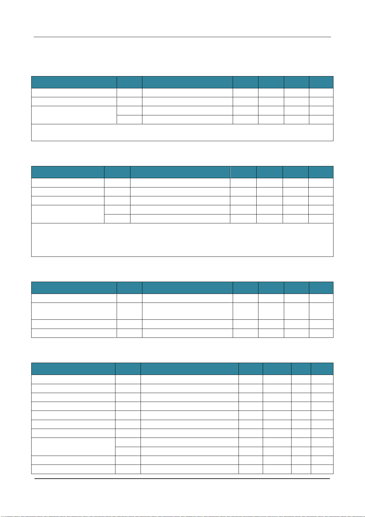
CMT2380F17
Rev0.1 | 19/347
www.cmostek.com
1.13 Controller ILRCO Characteristics
Parameter
Symbol
Condition
Note
Typ.
Max.
Unit
Supply power voltage
1.8
3.6
V
ILRCO frequency
TA = +25°C
32
KHz
ILRCO frequency deviation
TA = +25°C
-8[1]
+8[1]
%
TA = -40°C ~+85°C
-20[1]
+20[1]
%
Notes:
[1] The data is based on the characteristics, not from product test.
1.14 Controller CKM Characteristics
Parameter
Symbol
Condition
Note
Typ.
Max.
Unit
Supply power voltage
TA = -40°C ~+85°C
2.4
3.6
V
Clock input range
TA = -40°C ~+85°C
4.5[1]
6.5[1]
MHz
CKM startup time
TA = -40°C ~+85°C
30[2]
100[2]
us
CKM power consumption
TA = +25°C ,VDD = 3.6V,CKM=96MHz
350
uA
TA= +25°C ,VDD = 3.6V,CKM=144MHz
450
uA
Notes:
[1]. Data is guaranteed by design, not from test.
[2]. The data is based on the characteristics, not from product test
1.15 Controller Flash Characteristics
Parameter
Symbol
Condition
Note
Typ.
Max.
Unit
Supply power voltage
TA = -40°C ~+85°C
1.8
3.6
V
Flash write (erase, program)
voltage
TA = -40°C ~+85°C
1.8
3.6
V
Flash erase, programming cycle
TA = -40°C ~+85°C
20,000
、
次
Flash data retention period
TA = +25°C
100
年
1.16 Controller ADC Characteristics
Parameter
Symbol
Condition
Note
Typ.
Max.
Unit
Supply power voltage
TA = -40°C ~+85°C
2.4
3.6
V
Resolution
12
位
Integral nonlinearity
VDD = 2.4V~3.6V,400Ksps
-3.2
+3
LSB
Differential nonlinearity
VDD = 2.4V~3.6V,400Ksps
-2
+2
LSB
Offset error
VDD = 2.4V~3.6V
+6
+10
LSB
SAR conversion clock
24
MHz
Conversion time in SAR clock
30
Clocks
Conversion rate
VDD ≥2.7V
533
Ksps
VDD ≥2.4V
400
Ksps
VADC input voltage range
Single break(AIN+ to GND)
0
VDD
V
Input capacitance
9.17
10.58
pF

CMT2380F17
Rev0.1 | 20/347
www.cmostek.com
Parameter
Symbol
Condition
Note
Typ.
Max.
Unit
Input sampling switch
resistance[1]
VDD = 3.3V
968
Ω
VDD = 2.7V
1050
Ω
Switch from VDD to resistor
divider (VDD/2)
CH0(VDD)CH1(VDD/2, 51K resistor
divider)
4.3
uS
CH0(VDD)CH1(VDD/2, 10K resistor
divider)
0.7
uS
Switch from GND to resistor
divider (VDD/2)
CH0(GND)CH1(VDD/2, 51K resistor
divider)
4.1
uS
CH0(GND)CH1(VDD/2, 10K resistor
divider)
0.6
uS
ADC power supply current
ADPS<1:0> = 00
2.3
2.9
mA
ADPS<1:0> = 01
2.2
2.8
mA
ADPS<1:0> = 10
2.1
2.6
mA
ADPS<1:0> = 11
2
2.5
mA
Notes:
[1]. Data is guaranteed by design, not from test.
1.17 IVR Characteristics
Parameter
Symbol
Condition
Note
Typ.
Max.
Unit
Supply power voltage
TA = -40°C ~+85°C
2.4
3.6
V
Operating current
Normal power consumption state
43
67
uA
Low power state
0.1
uA
Output voltage
TA = -40°C ~+85°C
1.37
1.4
1.43
V
Spread over the temperature
range
VDD=3.3V±10mV
13
mV
Table of contents
Other CMOSTEK Transceiver manuals

CMOSTEK
CMOSTEK CMT2300A User manual

CMOSTEK
CMOSTEK CMT2310A User manual

CMOSTEK
CMOSTEK CMT2300AW Instruction Manual

CMOSTEK
CMOSTEK CMT2300A-EQR User manual

CMOSTEK
CMOSTEK CMT2300A User manual

CMOSTEK
CMOSTEK CMT2380F64 User manual

CMOSTEK
CMOSTEK CMT2300A Operating manual

CMOSTEK
CMOSTEK CMT2300A User manual

CMOSTEK
CMOSTEK CMT216 Series User manual


