CMP Brilliant Wonders 25597-72X-100 User manual

CUSTOM MOLDED PRODUCTS | 36 HERRING ROAD, NEWNAN, GA 30265 | WWW.C-M-P.COMjh0116
®
BRILLIANT WONDERS 8.5” COMPACT LAMINAR
25597-72X-100
25597-72X-100P
25597-72X-100H
25597-70X-000
CMP DOCUMENT 11120-000-004
4006147
LED WATERFALL | LED BUBBLER | LED LIGHTS | LED LAMINAR

2
Serious bodily injury can result if these lights are not installed
and used correctly.
Installers, pool operators, and pool owners must read these warning
and all instructions before using these lights.
Turn o power to light before installation/service. CMP Laminars are
equipped with a low voltage light and should never be electrically
connected to a power source other than an approved pool “Safety
Rated,” UL listed, outdoor rated, 12 VAC transformer. Failure to
comply will either damage or destroy the light and will void the
warranty.
Before installing this product, read and follow all warning notices and
instructions in this guide. Failure to follow warnings and instructions
can result in severe bodily injury, or property damage.
These lighted LED Laminars must be installed by a licensed or
certied electrician or a qualied pool professional in accordance
with the National Electric Code (NEC) or Canadian Electric Code
(CEC), CSA C22.1.
All applicable local installation codes and ordinances must also be
adhered to. Improper installation will create an electrical hazard
which could result in serious injury to pool users, installers, or
others due to electric shock. Always disconnect power to the pool
lights before servicing.
Save these instructions. This installation and user guide contains
important information about the installation, operation, and safe
use of this swimming pool/spa light. This guide should be given
to the owner and/or operator of this equipment.
No separate ground or bonding wire is required. The Laminars
have no exposed metal. They do not require a niche.
1. IMPORTANT WARNINGS & SAFETY
INSTRUCTIONS
NOTICE
NOTICE
DANGER
WARNING
WARNING
WARNING
WARNING
CAUTION

3
2. GENERAL INSTALLATION
INSTRUCTIONS
2.1 WATER SOURCE MUST BE FILTERED
The Laminar water supply must be ltered
by a cartridge lter (do not use a sand lter)
and be installed with a check valve. For up to
four laminar jet installations use a dedicated
lter that is a minimum of 50 sq-ft such as the
CMP lter 25504-600-000.
2.2 PUMP
The required minimum pump ow for each
laminar is listed in the table below:
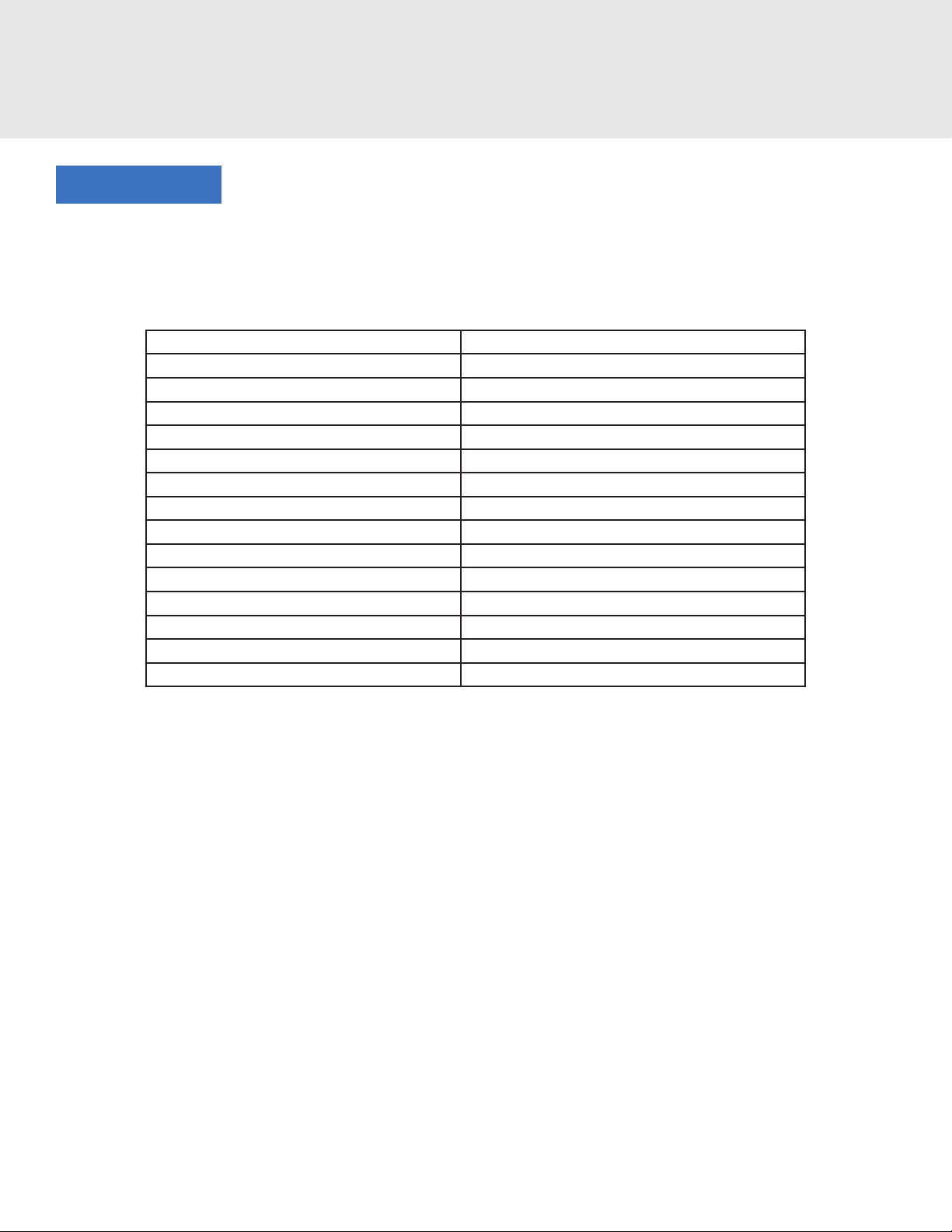
Laminar Jet Water Volume and Pressure Chart
Gallons (U.S. gpm) 2.5 3.0 3.5
Inlet Pressure (psi) 3.8 5.0 6.5
Height Estimate (ft) 2 3 4
Throw Estimate (ft) 3 4.5 6
*Estimates will vary depending on plumbing setup.
2.3 PLUMBING
Each laminar jet requires a 1” PVC entering
the deck canister. A check valve, such as CMP
Hydroseal 25830-704-000, should be installed
as far away from the laminar jet canister as
possible to minimize water turbulence. The
laminar canister is made from ABS material.
Use only ABS-PVC glue when making conduit
connections to this canister. Each Laminar
installed requires its own ball valve to adjust
ow on each line such as the CMP Ball Valve
25800-151-000.
2.4 LED LIGHT MODULE
The 12V LED light module oers vibrant
lighting and can be synced with a variety
of pool lighting products for the major
manufacturers. Reference the color
sync guide in the back portion of these
instructions.
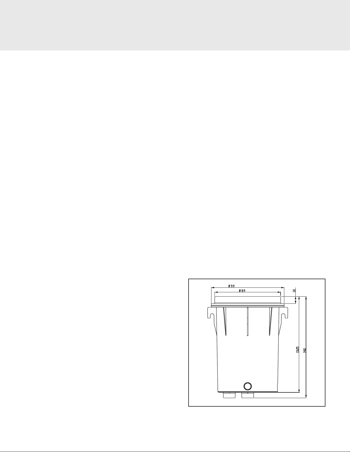
2.5 CRITICAL PLACEMENT DIMENSIONS
The maximum lighted distance of the laminar
stream should be considered 4 feet in height
and 6 feet in distance. If the laminar arc is
over 4 feet high there is a good chance that
the lighting will not travel the full distance to
the bottom of the laminar ow. If the throw
distance is over 6 feet the lighting will also fail
to go the full distance through the laminar
stream. Be sure the distance from the interior
pool wall to the Laminar is no further than 3
feet.
It is extremely
important that the water supply line
to each Laminar must be ushed so
that all debris material inside the line
is removed prior to being installed
into the Laminar. Foreign material
and debris will negatively aect the
performance of the fountain.
WARNING
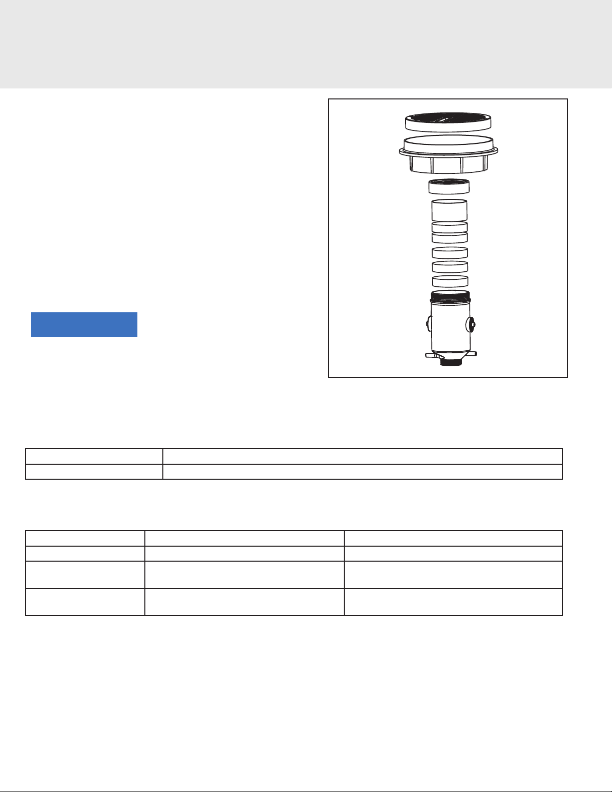
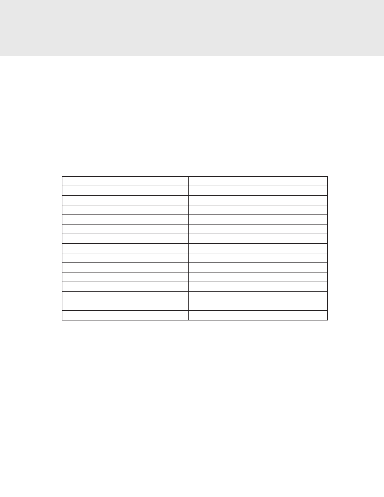
FIGURE 1: DECK CANISTER BOTTOM VIEW
3/4” ELECTRICAL
INLET (OPTIONAL)
1" DRAINAGE
SOCKET
3/4” ELECTRICAL
INLET (OPTIONAL)
3/4” WATER INLET
1” CENTER STAKE
SOCKET

4
3. INSTALLATION INSTRUCTIONS
3’
MAX
PUMP
PUMP
MANIFOLD
FILTER
FILTER
CHECK
VALVE
CHECK
VALVE
BALL
VALVE
CENTER
STAKE
DRAIN
LINE
BALL
VALVE
BALL
VALVE
BALL
VALVE
12V
TRANSFORMER
FIGURE 2: SUGGESTED PLUMBING DIAGRAM FOR Laminars
FIGURE 3: SUGGESTED PLUMBING DIAGRAM FOR MULTIPLE Laminars
WATER HEIGHT
4’ MAX
WATER THROW
6 ’ MAX

5
3. INSTALLATION INSTRUCTIONS
3.1 DECK CANISTER INSTALLATION
NOTE: Prior to installation, make sure the
opening on the Laminar canister lid is facing
toward the desired target location in the
pool. Make sure the deck canister is no more
than 5’ from the interior pool wall.
1. Dig a hole for the deck canister
approximately 24” deep and 18” in
diameter. This will ensure enough room for
positioning the canister and laying out the
plumbing. This depth will also allow for an
additional layer of pea gravel for stability
and extra drainage.
2. Set the deck canister in the hole. For “in-
deck” applications - level the top edge of
the lid to be ush with the nished deck
after the decking material is poured. For
planter areas - level the lid to be 2” above
the landscape area to prevent debris from
washing into the laminar jet.
3. Level the deck canister. To hold the
canister in place while the deck is poured
or installed, secure canister by placing the
center stake socket on a 1” pipe or use
rebar sockets on the side of the canister.
4. Plumb the incoming ltered water supply
to the 1” inlet on the side of the deck
canister, which is marked “WATER.”
5. Plumb the conduit for the LED cable to the
3/4" socket located either side of the deck
canister marked “ELECTRICAL.” It is highly
recommended to use sweep ttings for
ease of installation.
6. Plumb the 1" drain line to the drain
socket. Adequate drainage must be
provided for the deck canister.
NOTE: Proper drainage for the deck
canister is critical to avoid damage to
laminar jet assembly.
7. Verify the canister is level.
8. Fill excavated area with gravel until gravel
reaches 1" up from the bottom of the deck
canister.
9. Finish pouring/installing deck material.
10. Do not remove clear protective lm on the
deck canister lid until after the pool deck
has been installed. This is intended to keep
foreign debris from damaging or clogging
the Laminar.
FIGURE 4: FINISH HEIGHT
FINISH DECK
HEIGHT

6
4. LED LIGHT INSTALLATION/
WINTERIZATION
4.1 PREPARING THE LED LIGHT
INSTALLATION
NOTE: Ensure that the pool meets
requirements of the National Electric Code
and all local codes and ordinances. A licensed
and certied electrician must install the
electrical system.
1. The low voltage transformer must be
located at least 8 inches above the water
level, at least 4 inches above the ground
level, and at least 4 feet from the edge of
the pool.
2. All metal items within 5 feet of the pool
must be properly electrically bonded to a
reliable point of grounding.
3. Connect the male and female wire
connectors.
4. Feed cord through conduit from the
Laminar to the low voltage transformer.
Leave about 3 feet of cord coiled in the
bottom of the deck canister so that the
unit can be easily serviced.
5. Connect all wiring to the low voltage
transformer. Install cover for the
transformer.
6. Test to make sure the light functions and
the wiring has been done correctly.
4.2 WINTERIZATION STEPS FOR AREAS
WITH FREEZING CONDITIONS
1. Remove canister lid.
2. Carefully loosen and separate the garden
hose union on the water supply line inside
the deck canister.
3. Disconnect the male and female wire
connectors.
4. Blow water lines clear.
5. Remove jet body assembly and then
pour out remaining water from the body
by rotating it in all directions. Continue
dumping water until all water is removed.
6. Store jet body and all attachment
hardware together in a safe, dry location.
FIGURE 5: Laminar DIMENSIONS

7
5. MAINTENANCE/
TROUBLESHOOTING
5.1 FILTER MEDIA CLEANING
PROCEDURE
1. Remove Deck Housing Lid and pull
canister out of housing.
2. Unscrew deck canister cover and remove
sponge lter media.
3. Run low pressure water through the
sponge lter media to remove any excess
debris.
5.2 OPTIONAL ACCESSORIES
Part Number Description
25590-250-000 CMP Pool Fitting Multi-Tool
5.3 TROUBLESHOOTING
Problem Solution 1 Solution 2
Poor Stream Quality Remove Deck Housing and check for leaks. Refer to your pump manual to reduce pressure.
Poor Stream Quality Perform lter media cleaning procedure
outlined above
-
Lights Not Working Check power supply and controller and
verify that they are both turned on.
Check voltage at connector going into the light
module -- voltage should be 12VAC
Do not use any
detergents or cleaning chemicals to
clean the lter media. Use water only
for cleaning the lter media.
NOTICE
FIGURE 6: FILTER MEDIA

8
CMP/J-STYLE COLOR SELECTION AND SYNC INSTRUCTIONS
The CMP/J-STYLE Laminar is preprogrammed with the following color sequence:
SEQUENCE ORDER COLOR MODE
1 Alpine White
2 Sky Blue
3 Cobalt Blue
4 Caribbean Blue
5 Spring Green
6 Emerald Green
7 Emerald Rose
8 Magenta
9 Violet
10 Slow Color Splash
11 Fast Color Splash
12 America the Beautiful
13 Fat Tuesday
14 Disco Tech
To operate the light and change colors:
• Turn the light ON. The rst time the light is turned on, the color sequence will begin with Alpine White. To
change color, turn light OFF then back ON within three (3) seconds. Continue turning OFF and ON until
the desired light color mode is reached.
• When the light is turned o for more than seven (7) seconds, it will remain in the color mode that was
currently active when the light was turned o.
• To RESET the light to the beginning color sequence (Alpine White), turn the light OFF, wait four (4) to six
(6) seconds, then turn the light ON.
6. OPERATION AND SYNC
INSTRUCTIONS
When syncing multiple LED light products, color shows will match
but cycle timings may vary.
NOTICE

9
H-STYLE COLOR SELECTION AND SYNC INSTRUCTIONS
The H-STYLE Laminar Light is preprogrammed with twelve light modes:
SEQUENCE ORDER COLOR MODE
1 Voodoo Lounge
2 Deep Blue Sea
3 Afternoon Skies
4 Emerald
5 Sangria
6 Cloud White
7 Twilight
8 Tranquility
9 Gemstone
10 USA!
11 Mardi Gras
12 Cool Cabaret
To operate the light and change colors:
• The H-STYLE Laminar Light is operated through power-cycling; a method of changing modes which
requires no special controller or interface. To activate the light simply turn the power switch ON. To
advance to the next programmed light mode, turn the switch OFF then back ON within ten (10) seconds.
Whenever the light has been o for more than sixty (60) seconds, and it is rst turned on, it will come
on white for 15 seconds, then go back to the last programmed light mode it was running before being
powered o.
To sync the light with additional H-STYLE lights:
• The H-STYLE Laminar Light can easily be synced with additional H-STYLE lights. All lights should be
wired to the same switch. This should automatically sync the lights. If the lights get out of sync on the
same switch: turn the switch OFF, then wait between eleven (11) and fourteen (14) seconds and turn the
switch back ON. When the lights come back on, they should enter program mode number one (1) and be
synchronized.
6. OPERATION INSTRUCTIONS
[CONTINUED]

10
P-STYLE COLOR SELECTION AND SYNC INSTRUCTIONS
The P-STYLE Laminar Lights can be controlled using a standard wall-mount light switch. Multiple lights can
be connected via a junction box to a single switch so that all lights can be switched ON and OFF together.
P-STYLE Lights are controlled by cycling the AC power from a standard wall switch. By turning the switch ON
and OFF a specic number of times, the light activates one of the seven (7) light show modes, xed colors,
and enables the “Hold” and “Recall” feature.
The P-STYLE Laminar Light is preprogrammed with seven light show modes (1-7) and ve xed color
modes (8-12). For saving color eects during the “show” modes the light also includes and “Hold” and
“Recall” feature (13-14).
SEQUENCE ORDER COLOR MODE
1 SAm® Mode
2 Party Mode
3 Romance Mode
4 Caribbean Mode
5 American Mode
6 California Sunset Mode
7 Royal Mode
8 Blue
9 Green
10 Red
11 White
12 Magenta
13 Hold
14 Recall
Example to operate the light and change to “California Sunset” show mode:
• Turn the light switch ON and OFF six (6) times.
• During the ON/OFF switching process, no illumination will occur, then a white light will momentarily
illuminate.
• The white light will immediately be followed by the selected “California Sunset” mode.
Hold and Recall Features Example:
• Use the “Hold” feature to capture a unique color eect while “Romance Mode” is active.
• Turn switch on and o thirteen (13) times.
• Saved color eect is displayed.
• From any light show or xed color mode...
• Turn switch ON and OFF fourteen (14) times to activate last saved color eect.
• Saved color eect is displayed.
6. OPERATION INSTRUCTIONS
[CONTINUED]
This manual suits for next models
3
Table of contents