7
4A.System Electromechanical Overview
CAUTION Disconnect power before performing service. Refer to the IMPORTANT SAFETY INSTRUCTIONS displayed in
the front of this manual. Refer to Figures 3, 4 and 5.
NOTE: To replace a UV lamp, follow only SECTIONS 4B-1 and 4B-4.
There are two lamps in each UV reactor of the UV-C Pro powered by an energy ecient electronic ballast. Water enters the
UV reactor and is exposed to UV-C. The water exits the UV reactor to return to the process plumbing.
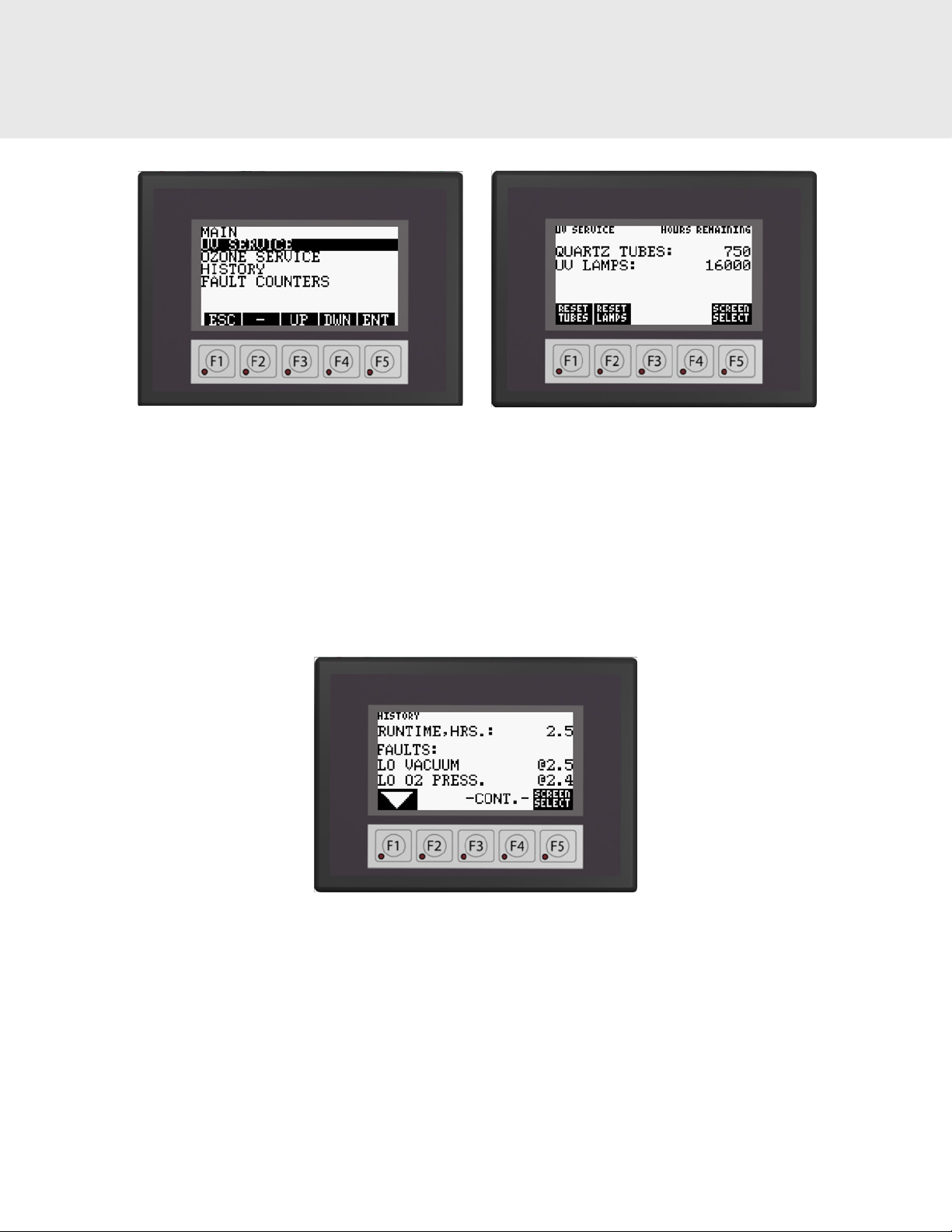
4B. UV Reactor Service and Maintenance
• Each UV Reactor contains two UV lamps and two quartz tubes.
• The UV lamps are designed to provide proper germicidal ecacy for 16,000 hours.
• The UV lamps may continue to glow well beyond 16,000 hours but will not provide proper intensity and must be
replaced to ensure ecacy.
• The UV lamps are housed in a quartz tube. If the quartz tube becomes dirty, its ability to transmit UV rays from the
lamp will be diminished.
• The service interval for the quartz tube is dependent on pool water chemistry and some pools may require more
frequent cleaning than others.
• Initially, inspect the quartz tube after 750 hours of use and clean as needed. Subsequent cleaning intervals can be
increased or decreased based on the condition of the quartz tubes or observed water conditions.
4B-1. UV Lamp Removal
1. Open the enclosure door.
NOTE: The UV-C Pro will not operate while the enclosure door is open.
2. After allowing adequate time for the UV lamps to cool, disconnect the UV lamp from the connector on the ballast.
3. Grasp the UV lamp wires and gently pull until the top of the UV lamp has pulled past the lamp retainer tabs.
4. Pull slowly on the white ceramic end of the UV lamp until the bottom has pulled past the lamp retainer tabs. If the
UV lamp is dicult to remove, use a slight twisting motion or remove the lamp retainer. AVOID TOUCHING THE
UV LAMP GLASS WITH YOUR BARE HANDS. Oils on your hands can cause hot spots on the UV lamp and shorten
its life. Use a soft clean cotton cloth or clean cotton gloves to handle the UV lamp. Carefully place the UV lamp in a
clean, dry, and safe location. Clean the UV lamp if necessary with alcohol and repeat this process for the other UV
lamps.
4B-2 Quartz Tube Removal and Cleaning
NOTE: For instructions on cleaning without mechanical disassembly, see Appendix.
1. If the UV-C Pro is mounted below the water level, system isolation valves must all be CLOSED to prevent excess water
from draining into the unit.
2. Loosen main inlet and outlet ttings on the UV-C Pro, this should allow sucient water to drain from the UV-C Pro.
3. Before continuing, allow adequate time for the UV lamps and quartz tubes to cool.
4. Remove the UV lamps as described in Section 4B-1.
5. Remove the front lamp retainer screws using the hex key included in the parts kit and remove the lamp retainer.
6. Grasp the quartz tube and pull it outward to remove it from the UV reactor.
NOTE: Additional water will drain from the UV reactor when the quartz tube is removed.
7. Remove the sealing O-ring from the quartz tube and set aside.
8. Wipe all residue from the quartz tube. If calcium deposits are encountered, use a mild solution (4:1) of water and
muriatic acid (available at pool supply stores), or household calcium/lime remover.
Follow the directions for use and handling of muriatic acid on the acid bottle label. Use proper eye and
skin protection and avoid breathing acid fumes.
NOTE: DO NOT USE ABRASIVE CLEANERS as they can scratch the high quality quartz glass. After cleaning the quartz tube,
wash it o and wipe dry. Inspect the quartz tube for cracks. Replace if cracks are found. Make sure the inside of the quartz
tube is dry before replacing the UV lamp(s).
CAUTION
4. MAINTENANCE & SERVICE