CNC SH-2100AH-QG User manual

Model SH-2100AH-QG
(V5.0-1.0)
CNC
Cutting Machine
User's Manual
Contents
Functional Overview
Main Menu
AUTO
MAN
EDIT
Command System
SETUP
LIBMINIT
DIAGNOSE
I/O Interface
Appendix
1. Pin definitions of height controller
2. SH-2012AH-QG Software
Upgrading Instructions
3. Installation Dimensional Diagrams
4. Troubleshooting
5. Wiring Instructions of Extended
Manual Control Box
www.collectcnc.com

All rights reserved
Forbidden to distribute or duplicate any file for the purpose of commercial, communication or others without
particular authorization. Compensation will be incurred if any clause is violated. All rights belong to Beijing
Starfire Control Technology Co., Ltd.
Disclaimer
We have made a consistency inspection to the contents of the printed file against the product described.
However, we can’t guarantee absolute accuracy due to the impossibility to eliminate inaccuracy completely.
Nevertheless, we will verify the information in the file regularly and make necessary amendments in the revised
version. Any suggestion for later improvement is greatly appreciated. Starfire reserves all the rights to make
necessary amendments on the basis of technical improvement.
www.collectcnc.com

Model SH-2100AH-QG Cutting Machine(C002)1
*Please Read This Manual Carefully Before Operating The System.
Precautions
1. After the container is unpacked, please check the system for any damage and verify if the contents in
the container are physically in conformance with the packing list.
2. This user's manual is applicable to Model SH-2012AH-QG CNC System for Cuttingmanufactured by
Starfire Control Technology Co., Ltd.
3. Please verify the conformance of local mains voltage. Be sure to use an AC220V isolation
transformer between the power supply network and the system to guarantee personal safety and
operating reliability.
4. The required ambient temperature for the CNC is ranged from 0℃to +40℃and the relative humidity
is from 0 to 85%.
Special protection is required in case of operating in a high temperature, high humidity or corrosive
gas environment.
5. Make sure the CNC is correctly wired and securely grounded.
6. Never try to hot plug/unplug any cable on the rear panel of the CNC, for the damage incurred thereby
is beyond our quality warranty.
7. No cable from the output port of the rear panel should be shorted with any power cable; otherwise,
the CNC might be burned.
8. Working in a very dusty environment, the whole system should be provided with dust protection in
addition to regular dust cleaning.
9. Trained operator should be specially assigned for the CNC.
10. The internal AC/DC power supply dedicated for the CNC should never share with any other electric
appliance.
11. The graphic programming software installed in the system is a beta version asking for advices,
which is subject to improvement in service and not taken as a requisite function and item for
acceptance. Please advise us timely in case of any debug in your use.
12. Please contact the manufacturer in case of any problem. Never disassemble, assemble or modify the
system the system without prior authorization and qualification.
13. Be sure to maintain the system and the cutting machine properly--routine maintenance and check
per shift, secondary maintenance per month and primary maintenance half a year.
14. Set the parameters in strict accordance with this user's manual or the supplemental instructions
given at placing order. The CNC might poorly function or even be damaged if the parameters are set
beyond the range.
15. The LCD screen is fragile and proper care is necessary in the process of operation.
16. The technical specifications are subject to change without prior notice.
17. Attention:
The provided USB port is very small in power output, only good for USB disk and not
recommended for any other USB device to prevent damage.
18. The system power must be cut off when alternating the internal keyboard and an extended keyboard.
19. Special Statement:
The quality warranty of this product is twelve months since its manufacturing date covering the
faults specified by this user's manual.
Paid service is available for faults caught beyond the warranty period and outside the quality
warranty coverage.
The following cases are not covered by the manufacturer's quality warranty:
A:Damage caused by misuse due to violating the operating instructions, and
B:Damage due to force majeure,
The force majeure is generally inclusive of two cases:
Natural causes such as thunderstroke, flood, drought, snowstorm, earthquake, etc.
Society causes such as war, strike, government prohibition, etc.
C:Damage caused by unauthorized actions such as disassembly, modification, repair, etc.
20. The final power of interpretation to this user's manual is subject to
www.collectcnc.com

Model SH-2012AH-QG Cutting Machine(C002)
1
Contents
Chapter I. Functional Overview...................................................................................................................................................................1
1.1. System Functions...........................................................................................................................................................................1
1.2Technical specifications...................................................................................................................................................................1
1.3Starfire also supplies the following auxiliary products for compact CNC cutting machine. ..............................................................2
Chapter II. Main Menu.................................................................................................................................................................................3
2.1.MenuFeatures....................................................................................................................................................................................3
2.2.DescriptionofMainMenu....................................................................................................................................................................3
ChapterIII.AutomaticFunction(AUTO).............................................................................................................................................................3
ChapterIII.AutomaticFunction(AUTO).............................................................................................................................................................4
3.1.DescriptionofAutomaticModeWindow...............................................................................................................................................5
3.2.FunctionselectioninAUTOmode.........................................................................................................................................................6
3.3. Startup of speed mode(multiplying factor) and automatic mode ..............................................................................................8
3.4. Control and adjustment of cutting position in automatic mode ................................................................................................8
3.5. Original Path Return ..................................................................................................................................................................10
3.6. Breakpoint Restoration Process .................................................................................................................................................11
3.7. SECTION(sectionselection)............................................................................................................................................................. 11
3.8. MOVE HOLE for Thick Plate....................................................................................................................................................12
Chapter IV. MAN(Manual Mode)..............................................................................................................................................................14
4.1.DescriptionofManualModeWindow.................................................................................................................................................14
ChapterV.EDITMode.....................................................................................................................................................................................16
5.1. Description of EDIT Menu .........................................................................................................................................................16
Chapter VI. Command System...................................................................................................................................................................18
6.1. Description of Programing Symbols ..........................................................................................................................................18
6.2.CoordinateSystem............................................................................................................................................................................18
6.3.G:BasicPreparatoryCommands.......................................................................................................................................................19
6.4. M Auxiliary Commands..............................................................................................................................................................23
ChapterVII.SETUP(ParameterSetting)............................................................................................................................................................25
7.1. Parameter Description................................................................................................................................................................25
7.2. SETUP(parameter setting) .........................................................................................................................................................26
7.3. FlameCuttingParameters...............................................................................................................................................................28
7.4.PlasmaParametersSetting.................................................................................................................................................................29
7.5.ControlParametersSetting................................................................................................................................................................30
7.6.ControlParametersSettingofHeightController.................................................................................................................................31
ChapterVIII.LIBMINIT(LibraryofPatterns)...................................................................................................................................................32
8.1.LIBMINITSetting............................................................................................................................................................................32
8.2. Selection of Pattern Elements.....................................................................................................................................................32
8.3. Arrangement and Layout of Pattern Element...........................................................................................................................33
8.4. User Defined Module.................................................................................................................................................................34
Chapter IV. Diagnose...................................................................................................................................................................................35
9.1 Check Input/output Ports ....................................................................................................................................................35
9.2 Output Check........................................................................................................................................................................35
9.3 Input Check ..........................................................................................................................................................................35
Chapter X. Connections of Input/output Ports.........................................................................................................................................36
10.1. System Input Principle..............................................................................................................................................................36
10.2. System Output Principle...........................................................................................................................................................36
10.3 Definitions of Input/Output Ports.......................................................................................................................................37
10.4 Definitions of 15-pin Ports for Motor .................................................................................................................................38
www.collectcnc.com

Model SH-2100AH-QG Cutting Machine(C002)2
10.5 Typical Wiring for Flame Cutting Operation(DB15)..............................................................................................................38
10.6 Typical Wiring for Plasma Arc Cutting Operation.................................................................................................................39
10.8 Pin Definitions .........................................................................................................................................................................40
Appendix I: The Wiring Diagram and Pin Definitions for Model SH-HC30 Height Controller Manufactured by Starfire..............42
Appendix II: Instructions for Software Upgrading Operation of SH-2012AH......................................................................................44
Appendix III: Installation Dimensional Drawing .....................................................................................................................................45
Appendix IV: Troubleshooting...................................................................................................................................................................46
Appendix V: Wiring Instructions for Extended External Manual Control Box.....................................................................................49
www.collectcnc.com

Model SH-2012AH-QG Cutting Machine(C002)1
Chapter I. Functional Overview
1.1. System Functions
Model SH-2012AH-QG CNC System for Cuttingis designed to work with torch/plasma, high-pressure
water jet and laser cutting machines and extensively used in metal working, advertisement fabrication and
stone machining businesses.
High reliability as well as good resistance to plasma disturbance, lightning and surge.
Applied torch/plasma cutting technology, able to perform corner speed control and height control
automatically;
Kerf compensation, reasonability check and report for user's option;
Breakpoint restoration, automatic power-back recovery and automatic breakpoint memory,
Random section and piercing point selection,
Extended piercing for thick plate and bridging feature for thin plate,
Optional piercing position feature in mode of RETURN, SECTION(section selection) and
RESBREK(breakpoint restoration), very convenient for user control,
Ready for transitional cutting operation at any moment,
Special short line machining feature based on smooth travel, extensively applicable to metal blanking as
well as advertisement and ironwork fabrication, etc.
Parts library of 24-type patterns, extensible and customizable, including the common machining parts,
Compatible with many blanking software such as IBE(Germany), FASTCAM, etc.
Operation menu both in Chinese and English, dynamic graphic display, 8-times zoom, free point automatic
tracking, USB disk program and timely software upgrade.
1.2Technical specifications
Processor: Industrial ARM7 CPU
Display: 7" Color LCD
Input/output: 13 channels of optical isolation input and 8 channels of optical isolation output
Interlocked axles: 2 axles, extensible to 4 interlocked axles
Maximum speed: <24m/min
Pulse equivalency: variable, electronic gear numerator and optional denominator in the range from 1 to
65535
Memory space: 32M-64M oversized memory capacity for user program and no restriction to machining
program
Machine case size: 298×202×95.2(mm)
Operation temperature: 0 to +40℃; storage temperature: -40 to +60℃
www.collectcnc.com

Model SH-2012AH-QG Cutting Machine(C002)2
1.3Starfire also supplies the following auxiliary products for compact CNC cutting
machine.
www.collectcnc.com

Model SH-2012AH-QG Cutting Machine(C002)3
Chapter II. Main Menu
2.1.MenuFeatures
The design of hierarchy-based functionalwindows is adopted forsystem operating display. If a function is invoked in the main
menu window, the corresponding subwindow menu will pop up. Press [F1] to [ F7] to select the corresponding function according to
windowprompt.PressESCtoabandontheselectionandreturntotheupperlevelofmenu.
2.2.DescriptionofMainMenu
VER:Theversioninformationofsoftwareandhardwareisindicatedatthebottomleftcornerforyourinformation.
[F1]AUTO:Programmedcontrolofautomatic machining
[F2] MAN: Tomanuallycontrolthepositionofcuttingnozzle
[F3]Edit: Toedit/modify/input/outputthemachiningprogram
[F4]SETUP: Tosetsystemparameters
[F5]DIAGNOSE:Tochecktheinput/outputinformationofcuttingmachine
[F6]LIBMINIT: Tosetnormalpatternandplanmaterial
[G][G][3]InitialSetting: Adialogboxasfollowswillappear:
Fig. 2.2 Initial setting dialog box
Fig. 2.1 Main menu display of system after booting
Display
space of
system
information
Software
version
Main Menu
Fileformat:toformatuser'sprogramspace;
Parameter:Torestorethefactoryparametersetting;
ENGLISH: Alternating between Chinese and
English
www.collectcnc.com

Model SH-2012AH-QG Cutting Machine(C002)4
ChapterIII.AutomaticFunction(AUTO)
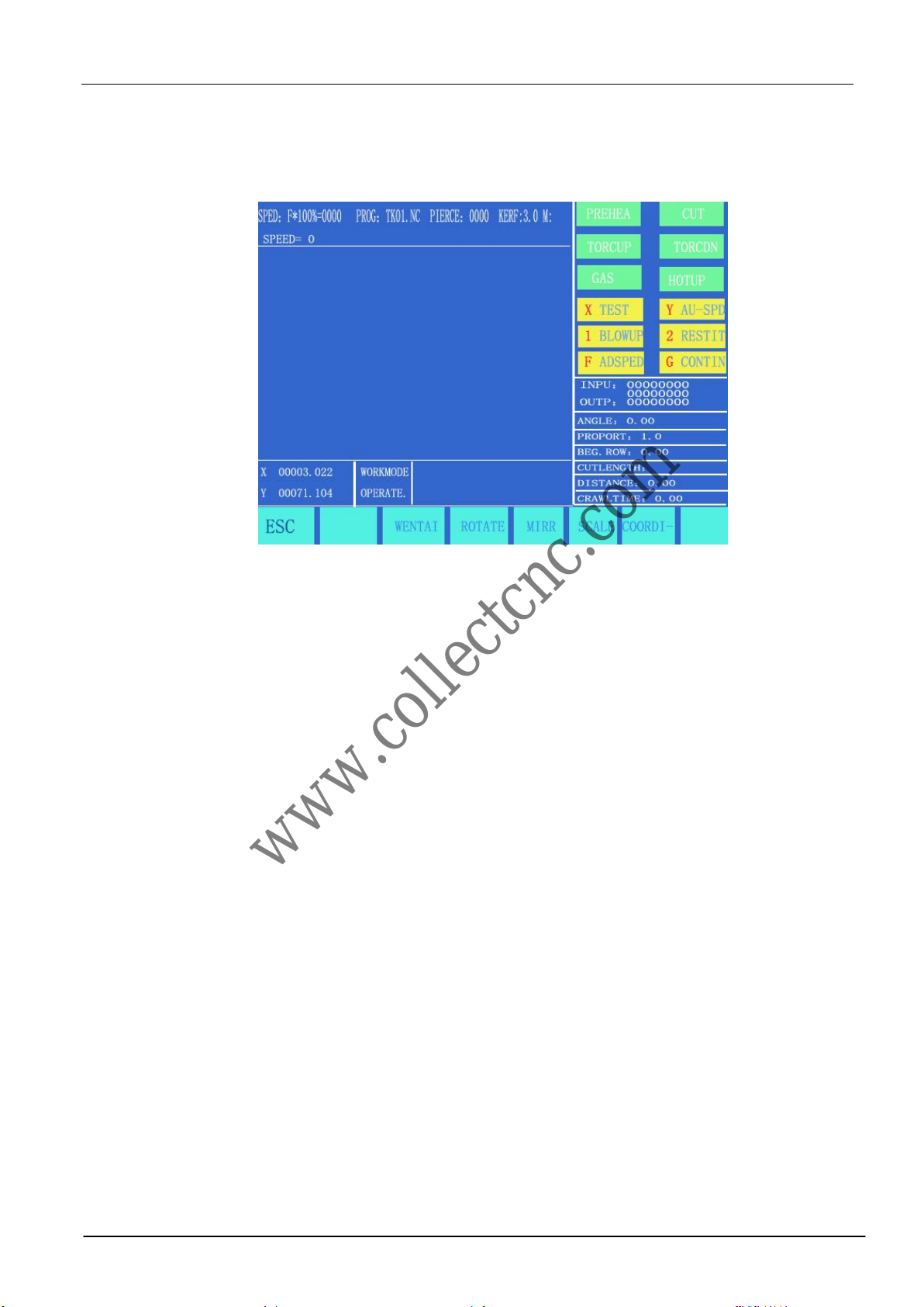
Inthemainmenu,press[F1]toentertheautomaticfunctionwindow,asshowninthefigurebelow.
Flamemode
Fig.3.1AutomaticFunction(AUTO)Window
Plasma Mode
Active speed multiplying
factor Program name Heavy-current control output
Piercing Hole No. Kerf
Input/output
indication
Function keys
Coordinates
Pattern
Display
Space
Machining
parameter
indication
Work mode
indication
Machining
program
www.collectcnc.com

Model SH-2012AH-QG Cutting Machine(C002)5
3.1.DescriptionofAutomaticModeWindow
3.1.1 SPEED
1) In automatic mode, at the top left corner of the screen, it shows F×(multiplying factor of automatic machining speed)= set
machiningspeed.
2) Inmanualmode,atthetopleftcornerofthescreen,itshowsF×(multiplyingfactorofmanualspeed)=manualspeed.
3) SPEEDindicatestheactualspeedwhiletheactivespeedmultiplying factor is adjustable with [F↑] and [F↓].
4) It is allowed to adjust the speed quickly by pressing [F] key in this window. Apull-down menu will appear with 8 speed
multiplying factors available for selection with [↑] and/or [↓] key: 5%, 20%, 30%, 40%, 50%, 60%, 80% and 100%. And
then,pressENTERkeytoacknowledgetheselection.
5) Attention:ThespeedmaybeindicatedinMetricorEnglishsystemdependingontheMetric/EnglishSelectioninSETUP
(RefertoParameterControl).
3.1.2 PROG,PIERCEandKERF
They are used to indicate the name of machining program, serial number of pierced hole(automatic clear in automatic machining
mode)andtheactivecompensatingwidthofkerfrespectively.
3.1.3WORKMODE,OPERATE
WORKMODE field indicates the active operating mode such as rotation selection, breakpoint recovery, mirroring and section
selection.
OPERATEfieldindicatessuchinformationasmachining/pause,limitalarmsandtimedelay.
3.1.4 Input and output
Below the heavy-current switches, there are 3 rows×8 indicators ○.
The top indicators show the status of 13 input ports, ○ indicating no signal input and ● indicating signal input.
The bottom indicators show the status of 8 output ports, ○ indicating no signal output and ● indicating signal
output.
See the description of DIAGNOSE function for the definitions of input/output ports.
3.1.5 Machining Parameters Indication
This zone indicates various parameter values in the current machining mode.
3.1.6 Selection of coordinate unit
The coordinates may be indicated in Metric(millimeter) or English system(inch) depending on the
Metric/English Selection in SETUP(Refer to Parameter Control).
3.1.7 The six heavy-current control keys on the front panel are designed to exert heavy-current control of
externalsource.
[IGN]: Refer to M20 for ignition feature.
[PREHEA]: To open the solenoid valve of preheating oxygen. Refer to M24 for details.
[GAS]: To open the solenoid valve of acetylene(gas). Refer to M10 for details.
[CUT]: To open the solenoid valve of cutting oxygen; refer to M12 for details. To turn on the arcing switch
if it is plasma.
[PIERCE] heavy-current control key
To carry out a piercing process, the specific operation procedure is as follows:
Flame machining case: rise the cutting torch(M72), open the cutting oxygen(M12) and lower the
cutting torch(M73).
www.collectcnc.com

Model SH-2012AH-QG Cutting Machine(C002)6
Plasma machining case: execute M07 command.
Note: This is a very important feature. It will be used repeatedly in pause, return and extend piercing
operations. When preheat is done, pressing [PIERCE] key will start up piercing operation
directly.
[SWOFF]: To shut off all the heavy-current output.
[S↑]: Push it down to rise the cutting torch and release to stop the torch.
[S↓]: Push it down to lower the cutting torch and release to stop the torch. ;
3.1.8[1] BLOWUP
The pattern will be magnified one times by one keystroke and it can be magnified to eight times maximum by
three keystrokes.
3.1.9 [2] RESTIT
To restore to normal pattern size.
3.1.10 [X] TEST
If [X] key is pressed, the system will run the program at top speed without executing Mcommand. This
feature is often used to position quickly or check the working size of steel plate. This operation can be paused at any
moment or cancelled by pressing [X] key one more times.
3.1.11 [Y] AU-SPD
Since the manual speed and automatic speed is separate in the system, this key is used to switched between
automatic mode and manual mode to adjust the speed multiplying factor.
3.2.FunctionselectioninAUTOmode
It is allowed to invoke a machining programby means of EDITfeature.If aprogramhas been invoked(aslongasit is the same
programname),itcanberundirectly.IftheprogramisinvokedfromanUSBdisk,especiallyalargeprogram,itcanberundirectlywith
USBdiskconnectedinsteadofsavingitintothesystem.
3.2. 1[F1] SECTION
To assign system to start up machining operation from any section or piercing point.
It is often used when machining needs to start from a certain section or only a part needs being processed.
Refer to SECTION feature for details.
3.2.2[F2] MAN
To switch the system to manual mode.
3.2.3[F3] RESBREK
After this function is selected, pressing [START] key to fulfill breakpoint restoration. Refer to RESBREK
feature for details.
3.2.4[F4] VIEW
It is used to test the program for any error. When this feature is selected, the pattern of machining program will
be displayed with a cross cursor at the origin.
[S] key is used to magnify the pattern, one times by one keystroke and eight times maximum by three
keystrokes. [Q] key is used to return the pattern to original size. The display position of pattern is moveable by
pressing [↑], [↓], [←] and/or [→] key.
3.2.5[F5] KERF
www.collectcnc.com
Model SH-2012AH-QG Cutting Machine(C002)7
This key is used to reminder input of kerf compensating width; if no necessary to compensate(usually in
blanking), simply enter 0.
3.2.6[F6] ASSI
This key is used to enter the next lower level of menu, as shown in Fig. 3.2 below.
3.2.7. [F3] ROTATE(steel plate correcting feature)
3.2.7.1Machining at rotation angle
This feature is used when the steel plate is not positioned perfectly or the steel plate needs to rotate an angle
before machining. It is allowed to use Rotate function along with BEG. PT. and END PT. in Manual mode or
input the expected angle directly. After acknowledged, the system will start the machining program at the
appointed rotation angle.
Note: Counterclockwise direction is taken as positive angle.
3.2.7.2Example
The system is able to identify and calculate the rotation angle by measuring the origin point and the end point
of an edge of steel plate(a straight line). The procedure is as follows:
1) Determine the datum line. Take one borderline of steel plate as baseline and move the cutting torch to the
origin point of this baseline. Press [F2] to set the beginning point of measurement.
2) Control the cutting torch and let it move along the baseline to the end point. The larger distance between
the beginning point and the end point, the more accurate of the measurement. Aim the cutting torch at the
baseline and press [F3] to set the end point of measurement.
3) At this moment, the rotation angle of the datum line is calculated. After the rotate function is fulfiled, the
rotation angle will appear in the OPERATE field, as shown in Fig. 3.2 below.
3.2.8[F4] MIRR
It is possible to select X Mirror, Y Mirror and No Mirror if press [F5] key continually. When X Mirror is
selected, the machining program will run along the symmetry direction of X-axis, as appears inverted
horizontally.
When Y Mirror is selected, the machining program will run along the symmetry direction of Y-axis, as appears
inverted vertically. When default No Mirror is selected, the machining program will run normally.
Fig. 3.2 ASSI window
www.collectcnc.com

Model SH-2012AH-QG Cutting Machine(C002)8
3.2.9 [F5] SCALE
The system will reminder user to input scale if this key is pressed. When the machining program is executed,
the work size will magnify or minify as per this scale. This feature is very useful in cutting graphic character.
3.2.10 [F2] WENTAI
The system will prompt to run WENTAI-based machining program if this key is pressed. WENTAI is a word
machining software for CAD/CAM, widely used in cutting graphic characters in advertisement business. This feature
is required to run a WENTAI-based program.
3.3. Startup of speed mode(multiplying factor) and automatic mode
3.3.1Manual speed and return speed
In either manual or return mode, manual multiplying factor is used to adjust speed.
Effective Speed=maximum speed limit * manual multiplying factor, where the manual multiplying
factor is adjustable with [F], [F↑] and [F↓] key.
3.3.2Machining Speed
Automatic multiplying factor is used to adjust machining speed.
Machining Speed=machining speed limit * machining multiplying factor, where the automatic
multiplying factor is adjustable with [F], [F↑] and [F↓] key.
These two speed multiplying factors are permanently saved and subject to no affect from power-off
operation once they are set.
3.3.3Start of automatic mode
1) Prior to starting automatic mode,
Select correct machining program and appropriate machining speed(multiplying factor). Move the cutting
torch to the cutting position. The cutting torch will be lifted automatically after a machining program is
initiated(to execute M70).And now, it is ready to start the machining program in automatic mode.
2) Two starting methods in automatic mode:
a)Press the green [START] key on the front panel.
b)Press an external "START" key(See the definition of input/output ports).
3.4. Control and adjustment of cutting position in automatic mode
3.4.1 Onlythefollowingkeysareenabledwhenthesystemstartsautomaticmode:
1)[PAUSE]: If this key is pressed, the system will slow down and stop movement, shut off cutting oxygen(shut
off arcing switch in plasma machining case), turn off the height controller(M39) and remain the current
display still. After the system operation is paused, it is allowed to perform the following operations:
(a) Return along the original path; (b)adjust position; (c)exit machining operation; (d) [START]: restore
system operation; and
(e)Press [ESC] key to exit the machining program and return to automatic mode window.
2) [F↑] and [F↓] speed adjusting key: To increase or decrease the multiplying factor of feed
speed.
3) [S↑] and [S↓] key: To control the vertical movement of cutting torch. By pushing and holding either key,
the cutting torch will move up or down accordingly, and the movement will stop if the key is released.
www.collectcnc.com

Model SH-2012AH-QG Cutting Machine(C002)9
4)[Emergency Stop] key: It is an external key with signal received from the input port(refer to "External Input
Ports" for details). If emergency stop is validated, all the movement will stop and no output will go on. It is
used for emergency case.
3.4.2.Adjustment of cutting position
3.4.2.1Situations necessary to adjust the position of cutting torch:
1)If the cutting torch is blocked or replacement is necessary, the usual practice is to move the cutting torch to
somewhere safe and move it back to the starting point after the situation is resolved.
2)When it is required to pierce along the exterior margin and not position the piercing point at the exterior
edge, the usual practice is to pinpoint an appropriate position in the exterior of workpiece for piercing and
then cut the workpiece back to the starting point along a straight line before continue normal machining
without stop.
3) In case of transitional cutting, too many workpiece or large size of workpiece, it might be necessary to
relocate the cutting torch.
3.4.2.2Situations allowed to adjust the cutting position:
(1) pause process, (2) return process,(3) piercing process, (4) section selection, (5) hole
selection and (6) breakpoint restoration
If operator intends to change the position of cutting torch in the above-mentioned states, it is allowed to
press [↑], [↓], [←] and/or [→] key to do so(in this case, it is manual multiplying factor, adjustable). When
the expected position is reached, press [Start] key, as shown in the following dialog box:
1)ORIPATHRET(originalpathreturn)
Returnthe cutting torch to the adjustmentbeginning point at speed G00and wait forother operation;at this step,it is allowed
to press an heavy-current function keysuch as IGN(ignition), PREHEA(piercing preheat), CUT(cutting oxygen), etc. Tip:
Thesystemwillcontinuetoprocessfromthebreakpointlocationif[PIERCE]keyispressedafterpreheating.
2)CUTRET(cutreturn)
After piercing, the cutting torch returns from the current position to the adjustment beginning point along a straight line at
cutting speed and continue machining along the original path without stop, which is somewhat like extended pierced,
makingthepiercingpointmoresmooth. ;
3)HOLEHERE(piercinghere)
After piercing, set the coordinates at current point as coordinates of "adjustment beginning point", and continue machining
alongtheoriginalpathtofulfilltransitionalpiercingfunction.
4)Attention:
Be sure to have the system preheated sufficiently(for flame cutting) before taking steps 2) and 3) , for piercing
operationwillstartrightawayoncetheoperationisselected.
Fig. 3.3 Dialog box of position adjustment options
www.collectcnc.com

Model SH-2012AH-QG Cutting Machine(C002)10
Itisrecommendedtopreheatthesystem(forflamecutting)andthenpress[START]keytoselectappropriateoperation.
3.5. Original Path Return
When it is necessary to return the cutting torch along the original path due to failure to cut through in
machining operation, handle it in the following ways:
3.5.1Return along original path
Press [PAUSE] key to suspend the running system. A "pause" mark will appear on the system display in
addition to prompt as shown in the figure below.
Press [F6] key to return the cutting torch along the original path .
Press [F7] key to advance along the original path after returning. In the process of return, if the cutting torch
fails to reach the required position, press [PAUSE] key again and repeat the above procedure until it reaches
the right position .
3.5.2 Return at G00(when reach a piercing point)
In the process of return, the cutting torch will stop at G00 or a piercing point for operator to select going on
return or advancing.
3.5.3 Operation after returned
After the cutting torch returns to the designated position, it is allowed to select position adjustment of cutting
torch(refer to 3.4) or piercing directly by pressing the appropriate heavy-current function key such as
PREHEA(piercing preheat) and CUT(cutting oxygen).
It is common practice to--
Press [PIERCE] key after preheating operation is done, or
For flame cutting operation, press CUT key(open the cutting oxygen) if the cutting torch lifts or
continue machining if the cutting torch lowers; or
For plasma cutting operation, ignite arc and do not go on machining until the arc ignition is
completed.
3.5.4 Repeat the above operation procedure until the desired effect is achieved.
3.5.5 To exit machining mode
In pause state, press [ESC] key to exit machining mode.
3.5.6 Total row number and beginning row in return process
The program segment for return allows 300 rows maximum. In case of breakpoint restoration(RESBREK) or
machining section selection(SECTION), the return beginning row is the row containing the current
breakpoint or the section selecting row, upon which however the cutting torch is not allowed to return along
the original path for machining.
Fig. 3.4 Machining pause display
www.collectcnc.com

Model SH-2012AH-QG Cutting Machine(C002)11
3.6. Breakpoint Restoration Process
3.6.1.Breakpoint restoration
1) In case of manual pause or power outage in machining operation, the system will automatically save the
current position of cutting torch as a breakpoint, which will be kept permanently in the system, whether
power the system off or not.
2) In automatic mode, press [F2] key to select RESBREK function and then [START] key to start breakpoint
restoration as long as there is no change with the current program.
3) If the position of cutting torch does not change, the system will prompt "Breakpoint" when a breakpoint is
found and wait for subsequent command. User may select piercing directly or position adjustment of
cutting torch. Refer to 3.4 for details.
4) If the position of cutting torch does change and is off from the breakpoint, the system will provide three
options when a program breakpoint is found, which is virtually position adjustment of cutting torch.
ORI PATH RET: To return to the breakpoint at speed G00, which is often used for the breakpoint set for cutting torch
replacement;
CUT RET: little bit off from the breakpoint after breakpoint restoration, whic is somewhat like piercing along the exterior
margin,makingthebreakpointmoresmooth;
HOLEHERE:thesameoperationasprevious,whichcanalsobeusedfortransitionalcutting.
Now, it is allowed to press a heavy-current function keysuch as IGN(ignition), PREHEA(piercing preheat), CUT(cutting
oxygen),etc.
Tip:Thesystemwillcontinuetoprocessfromthebreakpointlocationif[PIERCE]keyispressedafterpreheating.
If press [ESC] key when a breakpoint is found, the system will exit machining mode.
3.6.2Attention:
Never try to change the machining program, rotation angle and scaling proportion whether it is
breakpoint restoration or power-off restoration, which will be automatically saved by the system and
free from affect by power-off operation; otherwise, the system can not find the breakpoint.
3.7. SECTION(sectionselection)
3.7.1. StartSECTIONfunction
SECTION:toassignsystemtostartupmachiningoperationfromanysectionorpiercingpoint.
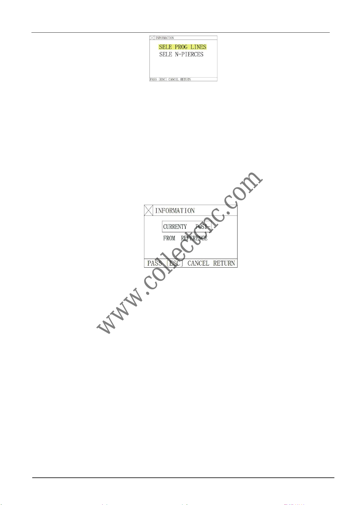
Press[F1]toselectSECTIONfunctionandthesystemwillshowamenuasshowninthefigurebelow:
Fig.3.5 Dialog box of restart options after system pause and breakpoint restoration
www.collectcnc.com
Model SH-2012AH-QG Cutting Machine(C002)12
Move the cursor with [↑] or [↓] key and make one choice from two machiningoptions.
Accordingtoyouroption,thesystemwillprompttoinputtheserialnumberoftheoption(programlinenumberortheserial
numberofpiercingpoint).
3.7.2.TwocasesforSECTIONmachiningoption:
3.7.2.1Transitionalmachining:tostartmachiningsomewheredifferentfromthestartpositionoftheprogram;
3.7.2.2Repeatthemachiningopearationstartingfromacertainsectionoftheprogram.
1)For the former case, a scrap work piece is often used for aiming at the piercing point and machining directly(HERE
POSITIONoption);
2)Forthelattercase,thereferencepointisusedforpositioning(REFPOSITIONoption).
3)Forthesetwooptions,thesystemwillpromptanoptionmenuasshownbelowafterstartup:
a) If "HERE POSITION" option is selected, the system will draw the full pattern first and then draw a large cross
cursoratthepiercingpoint.Operatormaypress[S]keyto zoominthepatternandobserveifitistheexpectedpiercing
position.Ifnotsatisfied,operatormaypress[ESC]toexitthemachiningmodeandtaketheoptionagain.
b)If it is the expected piercing point, use heavy-current control switch for ignition and preheat before
press [PIERCE] key to start operation.
c) If "REFPOSITION" option(Reference Point Positioning) is selected, operator should aim the cutting
torch at the reference point. After started up, the system will control the cutting torch to reach the
piercing point and then perform the operations as above.
3.8. MOVE HOLE for Thick Plate
1) In automatic mode, MOVE HOLE option is taken for thick plate.
2) For edge piercing method, it is important to move the cutting torch to the nearest edge of steel plate
before piercing operation.
3) Preheat the system and press [START] key at the end of preheat. The cutting torch will cut the steel plate
along a straight line to the piercing point at selected cutting speed and then go on machining.
4) When MOVE HOLE option is taken, it needs to change the MOVE HOLE option to 1 in the parameter
control menu, thus to enables the option. In this way, whenever it is time for piercing operation, the system
will prompt an option menu as shown below:
Fig. 3.5 SECTION function menu
Fig. 3.6 Option dialog box prompted by the system after machining start if SECTION machining is selected
www.collectcnc.com

Model SH-2012AH-QG Cutting Machine(C002)13
3.8.1HOLE
Topierceattheoriginalposition,whichisoftenusedforboring.
3.8.2MOVEHOLE
1)Operator may press [↑], [↓], [←] and/or [→] key to move the cutting torch to the edge of steel plate; in the mean time,
thespeedmultiplyingfactorisadjustedto5%automatically.Thesystemispreheated.
2)Press [START] key at the end of preheat. The cutting torch will reach the piercing point along a
straight line at selected cutting speed and then go on machining.
3.8.3NO HOLE
Instead of piercing, the system moves through the current piercing position to next, and new piercing prompt
appears.
Fig. 3.7 Option dialog box prompted by the system after reach piercing point if edge piercing method is selected
www.collectcnc.com

Model SH-2012AH-QG Cutting Machine(C002)14
Chapter IV. MAN(Manual Mode)
In main menu, press [F2] to enter MAN (manual) window, as shown in figure below:
Manual mode window(plasma cutting operation)
Manual mode window(flame cutting operation)
Fig.4.1 Manual mode window
4.1.DescriptionofManualModeWindow
The window display in manual mode is the same as it in automatic mode except that the multiplying factor is manually
adjustable,which affectsmanualoperation,returnspeedto referencepoint, move speed,etc..There aresome specialoperations in
Active speed
multiplying factor
Program name
Heavy-current control output
Piercing No. Kerf
Input/output
indication
Function keys
Coordinates
Pattern
Display
Space
Machining
Parameters
Indication
Main menu of
manual function
Workmode indicating
zone
www.collectcnc.com

Model SH-2012AH-QG Cutting Machine(C002)15
manualmodeasfollows:
4.1.1 [↑], [↓], [←], [→] directional control keys and [G] Continue Key
Generally, if any of the four direction keys is pressed and held, appropriate axial movement will carry on
until the key is released. However, if [G] Continue key is pressed and highlighted before any direction key is
pressed, the cutting torch will keep moving even if the key is released. The movement will not stop until the
direction key is pressed again. If two axial movements are required, let one axial movement start first and then
press the direction key for the other axial movement. Two axial movement will go on simultaneously. In this
case, the axial movement of cutting torch will stop if the corresponding direction key is pressed while the other
axial movement will go on until the corresponding direction key is pressed too. [PAUSE] key will stop the
movement as well.
4.1.2 【F1】AUTO
The system is switched to automatic mode.
4.1.3 【F2】MOVE
If MOVE function(highlighted) is selected, the system will prompt to input MOVE INCREMENT:
0050.000 (previous input value by default). In MOVE mode, if direction key is pressed once, the cutting
torch will move an increment at the speed of the current maximum speed limit multiplied by multiplying
factor.
4.1.4 [F2]P-START, [F3]P-END and Calibration function
This feature is used when the steel plate is not positioned perfectly or the steel plate needs to rotate an angle
before machining. Let the cutting torch go along a straight edge as long as possible. Pick up two points([F2]
for setting P-START and [F3] for P-END). The system will calculate automatically the rotation angle. Select
the ROTATE function in automatic mode. After acknowledged, the system will start the machining program at
the appointed rotation angle.
Note: Counterclockwise direction is taken as positive angle.
4.1.5 【F6】CLS-CO
Input X/Y coordinates with any value.
4.1.6 【F5】MDI
4.1.7 Speed
Atthetopleftcornerofthescreen,itshowsF×(speedmultiplyingfactorinmanualmode)=manualspeed.
It is allowed to adjust the speed quickly by pressing [F] key in this window. Apull-down menu will appear with 8 speed multiplying
factors available for selection with [↑] and/or [↓] key: 5%, 20%, 30%, 40%, 50%, 60%, 80% and 100%. And then, press RETURN key
toacknowledgetheselection.
www.collectcnc.com
Table of contents
Other CNC Cutter manuals


