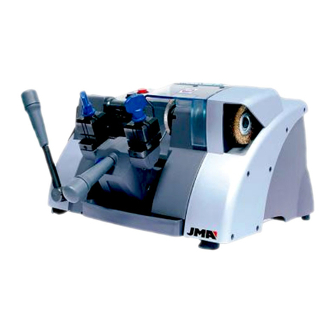
JMA AVANTCODE User manual

ELECTRONIC
AVANTCODE
USER GUIDE
Version 0.0

INDEX:
1INTRODUCTION AND OVERVIEW............................................................................................................1
1.1 OVERVIEW ........................................................................................................................................................ 1
1.2 TRANSPORT AND PACKAGING........................................................................................................................ 1
1.3 ID LABEL............................................................................................................................................................ 1
2MACHINE INSTALLATION AND CHARACTERISTICS ..................................................................................2
2.1 INSTALLATION ................................................................................................................................................. 2
2.2 DESCRIPTION OF THE MACHINE...................................................................................................................... 2
2.3 MAIN CHARACTERISTICS ................................................................................................................................ 4
2.4 KEY FAMILY ...................................................................................................................................................... 5
2.4.1 KEY TERMS .................................................................................................................................................. 5
2.5 MAIN PARTS OF THE MACHINE....................................................................................................................... 6
2.5.1 AVANTCODE (STANDARD) .......................................................................................................................... 6
2.5.2 AVANTCODE (KEY FEEDER) ......................................................................................................................... 7
2.6 TECHNICAL INFORMATION.............................................................................................................................. 8
2.7 MACHINE KEYBOARD AND KEY FUNCTION .................................................................................................... 9
2.8 CUTTING WITH ELECTRICITY.......................................................................................................................... 10
2.8.1 IMPROPER USE OF ELECTRICITY ............................................................................................................... 10
2.9 TYPES OF CUT ................................................................................................................................................. 11
2.10 ACCESORIES................................................................................................................................................... 12
3CONFIGURATIONS AND USE ................................................................................................................ 13
3.1 AVANTCODE (STANDARD)............................................................................................................................. 14
3.1.1 USING THE “MP1” STANDARD CLAMP.................................................................................................... 14
3.1.2 CUTTING CROSS KEYS .............................................................................................................................. 16
3.1.3 MOUNTING AND DISMOUNTING THE CLAMP......................................................................................... 17
3.2 AVANTCODE (KEY FEEDER) ............................................................................................................................ 18
3.2.1 USING THE AUTOMATIC CLAMP .............................................................................................................. 18
3.2.2 USING THE FEEDER.................................................................................................................................... 19
3.2.3 ASSEMBLY AND DISASSEMBLY OF THE AUTOMATIC CLAMP & FEEDER.............................................. 20
3.3 CONVERT THE AVANTCODE (STANDARD) INTO AN AVANTCODE (KEY FEEDER)......................................... 22
4OPERATION MANUAL .......................................................................................................................... 23
4.1 CUT KEY .......................................................................................................................................................... 24
4.2 READ FILE....................................................................................................................................................... 33
4.4 EDIT FILE ......................................................................................................................................................... 40
4.4.1 CREATE FILE ............................................................................................................................................... 40
4.4.2 MODIFY FILE............................................................................................................................................... 44
4.4.3 DELETE FILE................................................................................................................................................ 45
4.5 CONFIGURATION............................................................................................................................................ 45
4.6 MAINTENANCE .............................................................................................................................................. 50
4.6.1 Manufacturer values.................................................................................................................................. 50
4.6.2 Data connection ......................................................................................................................................... 50
4.6.3 Information................................................................................................................................................. 50
4.6.4 Speed ......................................................................................................................................................... 50
4.6.5 Password.................................................................................................................................................... 50
4.6.6 Other options.............................................................................................................................................. 51
4.7 PC OPERATION................................................................................................................................................ 53
5CLEANING AND SAFETY....................................................................................................................... 54
6MAINTENANCE.................................................................................................................................... 54

6.1 LOCATING MALFUNCTIONS........................................................................................................................... 55
6.2 REPLACING THE FUSES .................................................................................................................................. 56
6.3 REPLACING AND TENSING THE BELT ............................................................................................................ 57
6.4 REPLACING THE AUTOMATIC CLAMP SET .................................................................................................... 58
6.5 REPLACING THE MILLING TOOL ..................................................................................................................... 58
6.6 REPLACING THE CARRIAGE SENSOR............................................................................................................. 59
6.6.1 X AXIS ........................................................................................................................................................ 59
6.6.2 Y AXIS ........................................................................................................................................................ 59
6.7 REPLACING THE MOTOR ................................................................................................................................ 61
6.8 REPLACING THE KEYBOARD........................................................................................................................... 61
6.9 REPLACING THE LEDS..................................................................................................................................... 62
7WASTE DISPOSAL................................................................................................................................ 63
7.1 PACKAGING.................................................................................................................................................... 63
7.2 SHAVINGS ...................................................................................................................................................... 63
7.3 MACHINE........................................................................................................................................................ 64
8SUPPORT ............................................................................................................................................. 64
9CONSTITUENT PARTS .......................................................................................................................... 64

1
1INTRODUCTION AND OVERVIEW
1.1 OVERVIEW
The AVANTCODE key cutting machine has been designed in compliance
with EU safety regulations.
The safety of users of this type of machine is only achieved thanks to a
well designed safety program, the implementation of a maintenance
program and by following the recommendations for use, and complying
with the safety rules set out in this manual.
Although this machine is not hard to install, it’s advisable not to install,
adjust or handle it without having first read this manual.
The machine leaves our factory ready to use and only needs to be
calibrated for the type of operations for which it will be used.
1.2 TRANSPORT AND PACKAGING
The machine comes inside packaging with the following measurements:
Width = 640 mm, length = 770 mm, height = 575 mm
Machine weight including packaging = 60 kg.
Inspect the machine carefully on opening the parcel to ensure that no
damage occurred during transport. If there is an anomaly, please contact
the transport company immediately and do not use the machine until they
have carried out their inspection.
1.3 ID LABEL
The AVANTCODE duplication machine has an ID label (Fig. 1) showing
the serial number or machine registration number as well as the
manufacturer’s name and address, EC label and year of manufacture.
Fig.1

2
2MACHINE INSTALLATION AND CHARACTERISTICS
2.1 INSTALLATION
The machine has been assembled, calibrated and checked and is ready to use.
There is no need to perform any assembly operations. However, before using
the machine, it’s a good idea to carry out the following checks:
•Connect the AVANTCODE machine to a suitable power supply (220 V
50/60 Hz), in accordance with the information specified on the ID label
on the back of the machine.
•It is very important that the electricity supply is earthed. Ensure that the
machine is connected to the earth.
After unpacking the machine and connecting the power supply, move the switch
to position 1. (Fig.2).
Fig.2
Make sure the emergency button is not pressed down, if it is, release it.
When switched on, the JMA logo will appear alongside an internal test, then a
few moments later, the carriages will move to their start-up position (if not in
position already). The machine is ready to use.
2.2 DESCRIPTION OF THE MACHINE
The AVANTCODE machine has been designed to cut flat keys. The tiniest
details have been carefully designed to produce a compact machine that’s easy
to use and very precise. This is a mechatronic machine, with two stepper
motors for moving the carriages and a third motor to open the automatic clamp
(with key feeder).
One of the machine’s principle characteristics is that it allows you to use 2
different configurations without having to implement major changes. These two
options are as follows:
AVANTCODE (STANDARD): Standard clamp with 4 faces
AVANTCODE (KEY FEEDER): Automatic clamp and key feeder for
automatically cutting keys.

3
This is a versatile machine that can be used both with standard clamps or the
key feeder.

1
1INTRODUCTION AND OVERVIEW
1.1 OVERVIEW
The AVANTCODE key cutting machine has been designed in compliance with EU safety
regulations.
The safety of users of this type of machine is only achieved thanks to a well designed
safety program, the implementation of a maintenance program and by following the
recommendations for use, and complying with the safety rules set out in this manual.
Although this machine is not hard to install, it’s advisable not to install, adjust or handle it
without having first read this manual.
The machine leaves our factory ready to use and only needs to be calibrated for the type of
operations for which it will be used.
1.2 TRANSPORT AND PACKAGING
The machine comes inside packaging with the following measurements:
Width = 640 mm, length = 770 mm, height = 575 mm
Machine weight including packaging = 60 kg.
Inspect the machine carefully on opening the parcel to ensure that no damage occurred
during transport. If there is an anomaly, please contact the transport company immediately
and do not use the machine until they have carried out their inspection.
1.3 ID LABEL
The AVANTCODE duplication machine has an ID label (Fig. 1) showing the serial number or
machine registration number as well as the manufacturer’s name and address, EC label
and year of manufacture.
Fig.1

2
2MACHINE INSTALLATION AND CHARACTERISTICS
2.1 INSTALLATION
The machine has been assembled, calibrated and checked and is ready to use. There is no need to
perform any assembly operations. However, before using the machine, it’s a good idea to carry
out the following checks:
•Connect the AVANTCODE machine to a suitable power supply (220 V 50/60 Hz), in
accordance with the information specified on the ID label on the back of the machine.
•It is very important that the electricity supply is earthed. Ensure that the machine is
connected to the earth.
After unpacking the machine and connecting the power supply, move the switch to position 1.
(Fig.2).
Fig.2
Make sure the emergency button is not pressed down, if it is, release it.
When switched on, the JMA logo will appear alongside an internal test, then a few moments
later, the carriages will move to their start-up position (if not in position already). The machine is
ready to use.
2.2 DESCRIPTION OF THE MACHINE
The AVANTCODE machine has been designed to cut flat keys. The tiniest details have been
carefully designed to produce a compact machine that’s easy to use and very precise. This is a
mechatronic machine, with two stepper motors for moving the carriages and a third motor to open
the automatic clamp (with key feeder).
One of the machine’s principle characteristics is that it allows you to use 2 different
configurations without having to implement major changes. These two options are as follows:
AVANTCODE (STANDARD): Standard clamp with 4 faces
AVANTCODE (KEY FEEDER): Automatic clamp and key feeder for automatically cutting keys.
This is a versatile machine that can be used both with standard clamps or the key feeder.

3
The AVANTCODE machine, gives you the following options:
A database containing the key codes for locks, vehicles, etc. Flat keys in general. This gives you
tremendous flexibility and speed when cutting keys.
Connect the AVANTCODE to a compatible Intel PC with the Interactive Key Software (IKS)
installed. This program is a database containing key codes, identical to the machine’s database. It
provides a completely integrated working system (code search, selection of the bittings to cut,
additional information about the lock, complete digital JMA key catalogue, etc.)
Use the AVANTCODE to create your own keys using the laser reader that comes included in the
machine. Create and save your own new keys or enter the latest keys on the market into the
machine without having to wait for the database to be updated.
Use AVANTCODE to reproduce any type of flat key using the laser system.
Read the key code of a known key. Correct any cutting errors resulting from a variety of reasons
such as key wear, modification of the key data, etc.
2.3 MAIN CHARACTERISTICS
The main characteristics are described below:
•Movements
The 2 axes are moved using precision spindles that are activated by stepper motors on roller
guides.
•Standard clamp
Standard 4-sided clamp designed to grip almost all flat key models.
•Tool
Easy to replace, widia milling tool, with suitable resistance and cutting capabilities for this type
of work and rotation speed.
•Display screen
Located on the front of the machine, with an LCD Touch Screen measuring 5.7”.
•Laser reader
Laser for reading all keys to be copied.
KEY FEEDER
•Automatic clamp. (section. 3.2.1)
•Loading unit. (section 3.2.1)

4
2.4 KEY FAMILY
The AVANTCODE machine copies the following types of keys:
•Flat keys.
•Car keys.
•FORD, ABLOY and MAILBOX keys.
2.4.1 KEY TERMS
Diagram of a key showing the principle parts. (Fig.3)
1. Bow
2. Collar
3. Upper stop
4. Lower stop
5. Bittings
6. Blade
7. Back
8. Tip
1
2
43
75
6
8
Fig.3

5
2.5 MAIN PARTS OF THE MACHINE
2.5.1 AVANTCODE (STANDARD)
1. Milling tool.
2. Mill protector Fig.4
3. Standard clamp (MP1).
4. Mechanized clamp lever.
5. Clamp reading lever.
6. X carriage.
7. Y carriage.
8. Protective shield.
9. Keyboard.
10. Display screen.
11. Laser reader.
12. Shavings box.
13. Light.
14. Emergency button.
15. Mat.
16. Serial line cable (RS-232).
17. Socket.
18. On/off switch.
19. USB.
20. Ethernet.
1
2
4
6
5
7
3
9
8
11
12
13
15 10
14
2016 17 1819

6
2.5.2 AVANTCODE (KEY FEEDER)
1. Milling Tool.(Fig.4). Fig.5
2. Mill protector. (Fig.4)
3. Automatic clamp.
4. Loading unit.
5. Reader clamp.
6. X carriage.
7. Y carriage.
8. Protective shield.
9. Keyboard.
10. Display screen.
11. Laser reader. (Fig.4)
12. Shavings box.
13. Light.
14. Emergency button.
15. Mat.
16. Serial line cable (RS-232).
17. Socket.
18. On/off switch.
19. USB.
20. Ethernet
21. Key box.
12
3
8
4
13
5
6
7
10
14
21
9
15
2016 17 1819

7
2.6 TECHNICAL INFORMATION
The main technical information is set out below:
Motor........................ ..........................Single phase 220V, 50 Hz, 0.25 Kw, 3000 rpm, 2.04
Amp.
Milling.......................... Widia
∅
70 x 16 x 5.25 mm.
Speed.......................... 1500 rpm.
Clamps........................ Four faced.
Movement.................... Via ball spindles activated by stepper motors on
roller guides.
Strokes.................... X= 40 mm.
Y= 100 mm.
Light...................................... LED
Dimensions............................ Depth: 650 mm, Width: 495 mm, Height: 420 mm.
Display screen........................ 5.7” LCD Touch Screen.
Weight................................... 55 kg
CLASS 1 LASER DEVICE
•Maximum radiation excluding safety block: 200 μW
•Wavelength: 780 nm (not visible)
•Classified according to: EN 60825-1:1994 + E.C.1995 + A1:2002 + A2:2001

8
2.7 MACHINE KEYBOARD AND KEY FUNCTION
The machine keyboard basically comprises a Touch Screen LCD, with some raised keys for correct
use and an emergency button. The touch screen only uses icons and the raised keys are used in
all of the various screens (Fig. 6)
•This is a confirmation key. It’s the equivalent of ‘RETURN’ on a computer, used
to confirm the on-screen option and continue to the next menu, to save the information
from the keyboard and the computer.
•Cancel button, cancels the text on the screen, can also be used to exit a
previous menu or return to the main menu.
•Used to start the cutting operations and, if the cycle has stopped, to re-start it.
•Used to stop cutting operations.
•Used to delete the characters entered on screen.
Buttons to move
the cursor up,
down, left and
right.
Emergency
button
TOUCH SCREEN
PC connection
button
Icons
RAISED KEYS
Fi
g
.6

9
•The alphanumeric keys are used as follows:
•Each number has its own key.
•The letter keys work as follows:
1. To select the first letter, simply press it once.
2. Select the second letter on the keyboard by pressing the same key twice.
3. Select the third letter on the keyboard by pressing the same key three times. If you press
the same letter more than three times, it will go back to the first letter and so on.
2.8 CUTTING WITH ELECTRICITY
The machine comes equipped with a low current that enables numerous improvements when
cutting keys (Fig.7), such as:
a) Placing the key in the best clamp face (1, 2, 3, 4) to ensure a better grip.
b) Avoiding the need for pins and/or adaptors.
When the electricity is switched on, the cutting depth is automatically calculated once the key is
touched. Electricity can be used with steel, brass and zamak keys.
To activate the electricity, go to the final screen of the cutting menu, under the electricity section
and then press the START button (Fig.8)
Fig.7 Fig.8
2.8.1 IMPROPER USE OF ELECTRICITY
Do NOT cut anodized aluminum, plastic or other non-conductive materials.
CUT KEY
Cut key
New bittings
Number of keys
Cut - electricity
Type of cut - NORMAL
Material:
Steel-Nickel Silver
Electric contact

10
2.9 TYPES OF CUT
The machine can cut 3 different types - normal, ideal and flat. This option appears on the various
machine options - cut key, read key, copy key, edit key (see section 4.1). The cutting option is in
the last screen in the cutting window (Fig.9)..
Fig.9
CUT TYPES:
Normal: For standard vehicle and lock keys.
Ideal: This is the most innovative vehicle key - the join between the bitting angles is
automatically calculated by the AVANTCODE machine, to achieve variable angle
combinations. This makes it easier to move the key and prolongs the life of the lock.
Flat: Used particularly in vehicle keys, where bitting edges are eliminated to
make it easier to move the pins or covering when the key is inserted in the
lock.
Vertical: Used in special mailbox keys, for example Ford, Abloy, etc. A special
milling tool is required.
Radial: Used to produce a round between the base and the exit angle of the
key.
CUT KEY
Cut key
New bittings
Number of keys
Cut - electricity
Type of cut NORMAL
Material:
Steel-Nickel Silver

11
2.10 ACCESORIES
The AVANTCODE machine comes with a box of accessories for maintenance and repairs
(Fig.10). The following accessories are included::
18 mm spanner
2 mm Allen key
Fuse: T4A 250V
Mill blocking bar
2.5 mm Allen key
Stylus Touch scream
Brush
3mm T-shaped Allen key
USB
Set of tip stops
4mm Allen key
Set of II tip stops
5mm Allen key
Set of III tip stops
Calibration template
Fig.10

12
3CONFIGURATIONS AND USE
The AVANTCODE machine can have two separate configurations:
1. AVANTCODE (STANDARD): Clamp and reading clamps (Fig.11)
Fig.11
2. AVANTCODE (KEY FEEDER): Automatic and loading clamp and reading clamp
(Fig.12)
Fig.12
Automatic
clam
p
Feeder Reading
clam
p
Standard clamp
MP1
Cutting clamp Reading clamp

13
3.1 AVANTCODE (STANDARD)
3.1.1 USING THE “MP1” STANDARD CLAMP
The machine comprises two clamps, a clamp and a reading clamp. The keyblank to be cut is
placed in the clamp and the original key is placed in the reading clamp.
The key is fastened in the standard “MP1” clamp designed to hold various key types.
You have to consider two aspects when gripping the key: The side and top of the key.
•Side 1, 2, 3 and 4.
The standard clamp has 4 faces (numbering engraved on the top of the clamp)
allowing you to clamp the profile and back of keys. The standard clamp is
designed to hold various types of key.
The different sides and characteristics of the key to clamp are described
below:
a) Cutting keys supported on the back:
Side 1: keys with normal blades.
Side 2: keys with narrow blades.
b) Cutting keys by clamping the key by its profile:
Side 3: Key with guide on the lower part.
Side 4: Key with guide on the lower part.
Diagram of the standard model with images of the various clamps (Fig.13).
Fig.13

14
•Key stop.
Once you have selected the side of the clamp, position the key lengthwise, bearing in mind the
key stop. There are two types of stop, depending on the key model:
1. Collar stop (C): This is the most common type. The key is stopped by mechanically
blocking the clamp (Fig.14)
Fig.14
2. Pointed tip (1, 2, 3): The key tip is produced using the tip stop supplied as an accessory,
which is placed in the standard clamp slot beside the key.
Example of a key placed in side 1 and tip 2
(Fig.15)
Tip stop
Table of contents
Other JMA Cutter manuals