Coats CHD-9041 Manual

OPERATING AND MAINTENANCE INSTRUCTIONS
Electro-Hydraulic Tire Changer
For Medium and Large Size Tires
CHD-9041
8501077/00
Revision 06/08
READ these instructions before placing unit in service KEEP these
and other materials delivered with the unit in a binder near the
machine for ease of reference by supervisors and operators.
IMPORCOM EQUIPOS AUTOMOTRICES
Blvd. Leyva Solano #830 A Pte.
Culiacan Sinaloa CP 80000
(667) 276 8141
(667) 716 0102
ID 92*1038450*4

2
INDEX
1 - GENERAL INFORMATION...............................................................................................................................................3
2 - TECHNICAL DATA...........................................................................................................................................................3
3 - GENERAL SAFETY REGULATION.....................................................................................................................................3
4 - SAFETY DEVICES.............................................................................................................................................................3
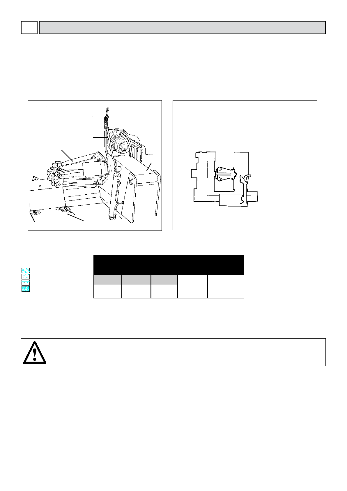
5 - TRANSPORT.....................................................................................................................................................................4
6 - UNPACKING...................................................................................................................................................................4
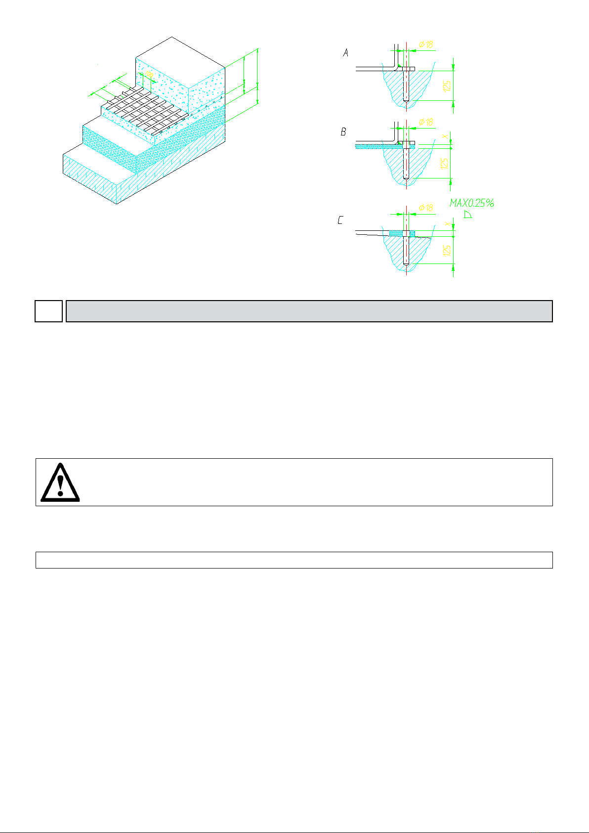
7 - INSTALLATION ................................................................................................................................................................4
7.1 Installation place...............................................................................................................................................................................4
7.2 Workplace requirements..................................................................................................................................................................5
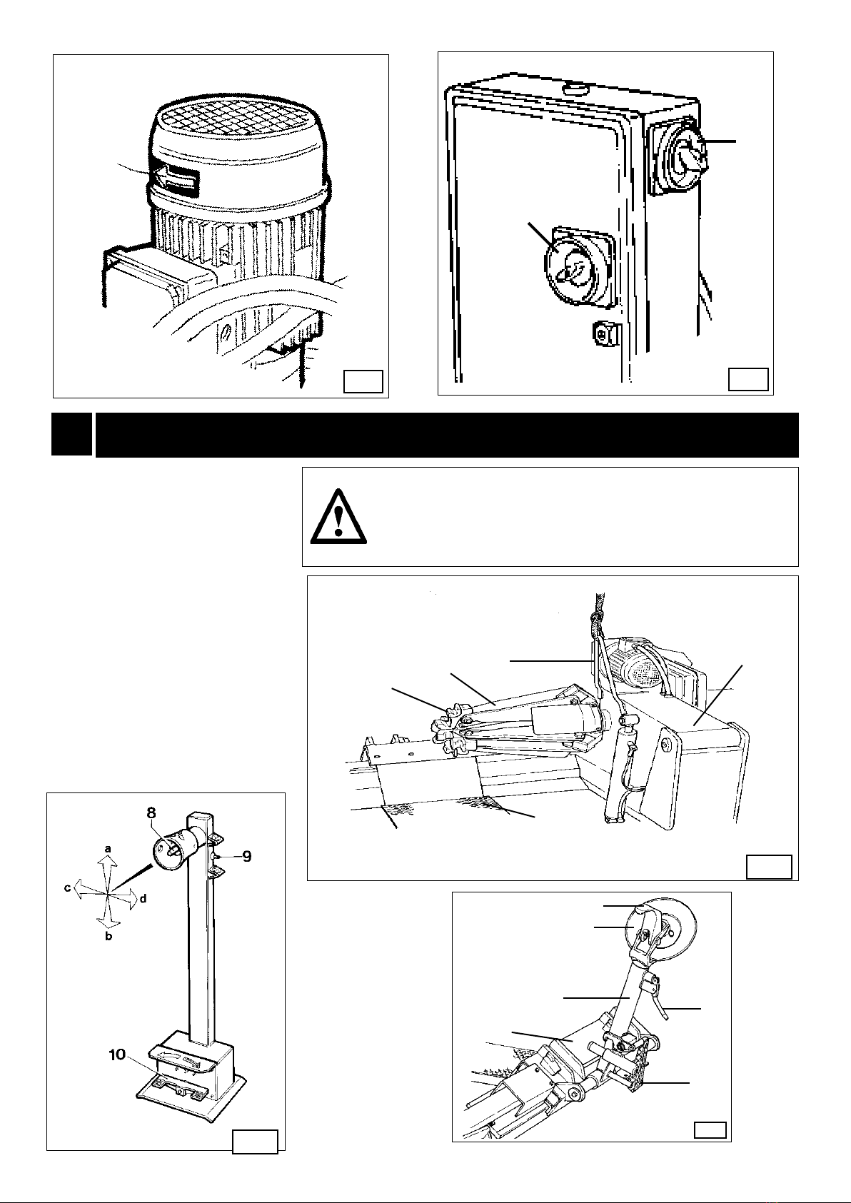
7.3 Electric hook up.................................................................................................................................................................................6
Sense of rotation check
8 - LAYOUT OF FUNCTIONAL PARTS...................................................................................................................................7
9 - IDENTIFYING WARNING SIGNALS.................................................................................................................................8
10 - IDENTIFICATION OF CONTROL....................................................................................................................................9
11- WORKING POSITION.....................................................................................................................................................9
12 - CORRECT OPERATION CHECKS..................................................................................................................................9
13 - OPERATION.................................................................................................................................................................11
13.1 Rim clamping......................................................................................................................................................................................11
Light-alloy rim clamping
13.2 Tubeless and supersingle tires...........................................................................................................................................................12
Bead losening
Demounting
Mounting
13.3 Tubed tires...........................................................................................................................................................................................17
Bead losening
Demounting
Mounting
13.4 Rims with split ring...............................................................................................................................................................................20
Bead losening and demounting
Mounting
14 - ORDINARY MAINTENANCE.......................................................................................................................................24
15 - TROUBLE SHOOTING..................................................................................................................................................25
16- MOVING THE MACHINE.............................................................................................................................................25
17- STORING......................................................................................................................................................................25
18- SCRAPPING A MACHINE............................................................................................................................................26
19- DATA ON SERIAL PLATE...............................................................................................................................................26
20- ACCESSORIES..............................................................................................................................................................27

3
GENERAL INFORMATION
1
This tire changer has been specically designed to t and remove truck, bus and commercial agriculture and Off road tires, with rims
from 14" to 56" and a maximum 90” (2,300 mm) diameter.
Any other use is improper and therefore not authorized. Before beginning any kind of work on or with this machine, carefully read and
understand the contents of these operating instructions.
The Manufacturer shall not liable for any injury to persons or damage to things caused by improper use of this machine.
KEEP THIS MANUAL NEAR THE MACHINE AND CONSULT IT AS NEEDED DURING OPERATIONS.
Any work, however minor, on the electric system must be done exclusively by professionally qualied electrician.
2
TECHNICAL DATA
3
GENERAL SAFETY REGULATIONS
The use of this machine is reserved to specially trained and authorized personnel.
Any unauthorized changes or modications to the machine, in particular to its electric system, relieve the manifacturer from all liability
and warranty claims.
Removing or tampering with the safety devices installed on this machine is a violation of International Safety Regulations, and, as such,
once again relieves the manufacturer from all liability and warranty claims.
4SAFETY DEVICES
The tire changer has a number of safety devices designed to guarantee the utmost operator safety:
1. Check valve on the spindle opening hydraulic line (inside the swivel connector, see g. B/1). This prevents the wheel from falling from
the spindle if the hydraulic line is accidentally broken.
2. Pressure relief valve factory set at 1,885 PSI (130 bar) ±10% (See Fig. B/2).
This limits the pressure in the hydraulic circuit and ensure correct operation of the plant.
3. Pump motor overload shut-off (inside the electric enclosure). This provides automatic shut-off for the motor to prevent damage from
overheating. This cuts in if the motor overheats to prevent it from burning out.
4. Check valve on the chuck arm lifting hydraulic line. This prevents the chuck arm from descending when any accidental break occurs
in the hydraulic circuit.
Pump motor
Gear-box motor
Handles rim from
Max. wheel diameter
Max. wheel width
Max. wheel weight
Weight (with standard accessories)
Acoustic pressure level (at work)
2.0 HP (1.5 kw)
1.7-2.4 HP (1.3 / 1.8 kw)
14" - 56"
90” (2,300 mm)
42” (1,065 mm)
3,300 lbs (1,500 kg)
1,698 lbs (770 Kg)
LpA <70 dB (A)
Electric Power requirement
220V - 3 PH - 60Hz 15 Amp

4
B/1 B/2
1,874 lbs
(KG. 850)
A/2
TRANSPORT
5
The machine is delivered in a wooden crate with pallet
The machine must be handled with a fork-lift truck with forks positioned as shown in gure A/2.
Shipping weight for the machine is 1,874 lbs (850 kg).
6
Once the packing material has been removed, check the machine visually for any signs of damage.
Keep the packing materials out of the reach of children as they can be a source of danger.
N.B.: Keep the packing for possible future transport.
UNPACKING
7INSTALLATION
Choose the place the machine is to be installed in compliance with current work place safety regulations. The oor should not be broken
or uneven so that the machine will be stable and the platform rollers can move freely.
If the installation is outdoor, it must be protected by some kind of roong against rain.
The following work environment conditions are applicable:
Relative humidity: from 30-95% without condensation;
Temperature: from 32°-131° F (0-55° C).
7.1
INSTALLATION PLACE
ATTENTION!
The machine must not be operated in explosive atmospheres.

5
B/5
A
98.4 inches
(2,500 mm)
1
3
4
2
7.2
The tire-changer must be installed on a levelled concrete oor at least 8” (20 cm) . thick, with a minimum concrete quality of B25 in
accordance with DIN 1,045 requirements (foundations).
For your reference see the side drawing as well as the table herebelow.
If a oor of this type is not available on site, fastening points of the specied concrete quality are acceptable.
The surface, on which the universal tire-changer is to be installed, must be at and well levelled in all directions.
Inclinations up to 0,25% relative to the horizontal can be compensated using suitable shims, wedges or alike.
By means of a Widia bit Ø 16 drill a 0.630 inch hole (130 mm) into the oor passing through the holes provided on the base frame.
If there is an additional oor covering (B), or if shims or wedges are necessary for levelling (C), longer anchor bolts must be used.
Place an anchor bolt into each hole.
Make sure the anchor bolts extend at least 4.90” (125 mm). into the concrete slab, as indicated in the drawing.
Tighten the anchor bolts completely.
Ground
Reinforced concrete
Electrowelded grid
Pebble gravel
Foundationsdimensions inch (cm). Concrete
quality
Min. pressure
resistence
Length Width Thickness
B25 937 lbs/sqft
(425 Kg / cm
2
)
78,74
(200)
64,5
(164)
5,9
(15)
When working with wheels, whose weight is higher than 2,204 lbs (1,000 kg)., it is necessary to fasten the
tire-changer to the oor by means of proper anchor bolts.
Maximum machine space requirements are 88.2X6.3 inches (2,240x 1,640 mm) with a minimum distance from walls as shown in the
diagram.
CAUTION! These measurements are also the tire changers working range. Persons other than specially trained and authorized operators
are expressly forbidden to enter this area.
Position the tire changer lifting it with the specic bracket (1, Fig. A) with the tool carrier arm (2, Fig. A) lowered all the way, the spindle
(3, Fig. A) closed and the tool carrier slide (4, Fig. A) at its stop close to the arm.
The mobile control unit has no xed position, but it must be
positioned in a way that the user can observe the machine when working
WORK PLACE REQUIREMENT
98.4 inches
(2,500 mm)
27.5 inches
(700 mm)
39.3 inches
(1,000 mm)

6
3,93
1,96
5,90
3,93
3,93
inches
7.3
ELECTRIC HOOK UP
Before making any electric hook up, check to be certain that the main voltage corresponds to that stamped on the voltage tag
(attached to the cord near the tire changer’s plug).
It is absolutely essential that :
- The system is equipped with a good grounding circuit.
- The current intake is adeguately protected against overcurrents with fuses or automatic magneto-thermic switch Note the
required power draw as highlighted on the data plate xed to the tire changer. Check to make sure the shop
electric wiring circuit is dimensioned sufciently to carry this.
Work on the electric system, even if minor, must be done exclusively by
professionally qualied electrician.
Manufacturer shall not be liable for any injury to persons or damage to things caused by failure to comply with these regulations and
can cancel warranty coverage.
Connect the machine to the mains, switch “ON” (5, g. B/7) and check that the gearbox motor rotation corresponds to the indicating
arrow (6, g. B/6).
If not, switch two wires in the plug .
SENSE OF ROTATION CHECKS
ø 0,31
inches
Ø 0,7
Ø 0,7
Ø 0,7
MAX 0,25%
4,9
4,9
4,9

7
B/6 B/7
12
5
6
8
LAYOUT OF FUNCTIONAL PARTS
1 - Lifting bracket
2 - Self-centering chuck holding arm
3 - Self-centering chuck
4 - Sliding ramp
8 - Handler
9 - Switch
10 - Pedal
13 - Carriage
14 - Tool holding arm
15 - Arm lever
17 - Bead losening disk
18 - Tool
19 - Pedal
22 - Jaw
WARNING!
During all operations, keep hands and other parts of the body as far
as possible from moving parts of the machine. Necklaces, bracelets
and too large clothes, can be dangerous for the operator.
A
4
31
22
2
CD
18
14
13
19
15
17

8
9
IDENTIFYING WARNING SIGNALS
WARNING:
Unreadable and missing warning labels must be replaced immediately.
Do not use the tire changer if one or more labels are missing.
Do not add any object that could prevent the operator from seeing the labels.
Use ref. code # 2019113 to order labels set, if needed

9
10
IDENTIFYING CONTROLS
The diagram B/8 illustrates the various working positions (A,B,C,D) referred to in the following pages describing how to use the tire changer.
Use of these positions ensures greater precision, speed and safety for those using the machine.
The mobile control unit (g. C) enables the operator to work at any position around the machine. On this mobile control unit the follow-
ing controls are located:
-The lever (8, g. C) which in position [a] lifts the chuck arm and in position [b] lowers it; in position [c] moves the tool holder arm and the
sliding table towards the self-centering chuck and in position [d] moves them away.
Note: in order to memorise this operation, there is a hole in the lever guard corresponding to position c.
-The chuck switch (9, g. C) when moved upwards, opens the arms of the self-centering chuck (LOCKING), and when moved down,
closes the arm of the self-centering chuck (UNLOCKING).
-The pedal (10, g. C) when pressed on the left or right side rotates the self-centering chuck in the same direction as shown by the ar-
rows placed on the foot pedal.
Both rotations can be made with two different speeds, just placing the selector (12, g. B/6) in position 1 for getting slow rotation and in
position 2 for fast rotation of the turntable
The tire changer also has:
Handle (15, Fig. D) to tip the tool carrier arm (14, Fig. 4) from its work to its non-working position and vice-versa.
Pedal (19, Fig. D) that permits alternative use of the bead-losening disk (17, Fig. D) or the hooked tool (18, Fig. D).
Pressing the emergency STOP BUTTON (12 g. C) will stop any operation in course
WORKING POSITION
CORRECT OPERATION CHECKS
12
Before using the tire changer, a number of checks should be made to ensure it works correctly.
CAUTION! The operations described here should be done with the tool carrier arm in its non-working position.
11
B/8
D
C
a
b
c
d
18
14
13
19
15
17

10
First use handle (15, Fig. D) to tip the arm to this position.
1) Move the joystick (8, Fig. C) up (a): the spindle carrier arm (2, Fig. A) should lift; move the joystick down (b): the arm should lower.
DANGER!
When the spindle carrier arm is lowered, there is always a potential for crushing anything in its
movement range. Always work from the position given in the instructions keep well out of the working
range of the various moving arms.
Move the joystick towards the left (c): the tool carriage and the mobile platform (13, Fig. D) should move towards the spindle (3, Fig. A);
move the joystick towards the right (d) the carriage and platform should move away from the spindle.
2) Turn switch lever (9, Fig. C) towards the top: the spindle arms (3, Fig. A) should open; move the lever down and the spindle arms
should close.
3) Depress the right pedal (10, Fig. C): the spindle (3, Fig. A) should turn clockwise; depress the left pedal: the spindle should turn counter
clockwise.
DANGER!
When the spindle arms open or closed, there is always a potential for crushing anything in their movement
range. Always work from the position given in the instructions keep well out of the spindle’s working
range.
CAUTION!
Do not move your face close to the tool carrier arm when you release it to tip it as needed.
D
C
E/1
18
14
13
19
15
4) Check to be certain the hydraulic circuit is working propenly:
- move switch lever (9, Fig. C) towards the top until the spindle arms are fully extended.
- hold the switch lever in this position (top) and check if the pressure shown on the gauge on the swivel tting is 1,885 PSI (130 bar)
±10%.
If the pressure shown in not as indicated here, DO NOT USE the tire changer and call your nearest Service Center.
17

11
13.1
RIM CLAMPING
13 OPERATION
WARNING!
In rim clamping, make sure that jaws are properly positioned on the rim, so as to prevent the tire from
falling over
1) Take the mobile control unit to work position B.
2) Pull the tool-holder arm (14, g. D) into the upright position.
3) Operating from the mobile control unit, move the sliding carriage (iten 13, g. D) away from the self-centering chuck and place the
tire assembly in vertical position oven the sliding ramp.
DANGER! POTENTIALLY HAZARDOUS OPERATION!
Do it manually only if you are certain you can keep the tire assembly balanced. For large and heavy tyres
an adequate lifting device must be used.
4) Continuing to operate from the mobile control unit, lift or lower the arm in order centre the self-centering chuck (3, g. A) relative to
the rim.
5) With the jaws (22, g. A) in the closed position, move the tire assembly on the sliding ramp to the self-centering chuck. Operate the
chuck switch (9, g. C) to open the self-centering chuck and clamp the inner side of the rim.
E/2 E/3
E/4 E/5

12
13.2
The most convenient clamping position on the rim may be selected according to gs E/1 - E/2 - E/3 - E/4 - E/5 and E/6.
Always remember that the safest locking is on the central ange.
For rims with a drop center clamping, clamp the wheel so that the drop center is near the outside of the rim (g. E/1).
For rims exceeding a diameter of 46" and without a ange with center hole, the rim can be clamped with the 4 clamping extensions
provided on demand (# 9299270)
(# 9299272) LIGHT-ALLOY RIM CLAMPING
A set of specialclamps - especially designed for operating on light alloy rims without damaging them - is available upon request.
These clamps are to be inserted (bayonet-like mounting) into the jaw support of the self-centering chuck (see g. E/7).
Thanks to a wing screw the clamp can be locked on the support.
Clamp the rim as illustrated in g. E/8. The specially-made alloy-rim pliers are also available (#9299272).
DANGER!
Do not walk across the work area with a wheel clamped on the tire changer and lifted up from the
oor.
TUBELESS AND SUPERSINGLE TIRES
BEAD LOSENING
1) Clamp the tire assembly on the self-centering chuck, as previously described, and ensure that the tyre is deated.
3) Lower the tool-holder arm (14, g. F) into is working position and allow it to lock.
2) Take the mobile control unit to work position C.
DANGER!
Always check to be certain that the arm is correctly hooked to the carriage.
E/6
E/7
E/8

13
5) Rotate the wheel and at the same time, advance the bead-loosener disk with small forward movements following the prole of the
rim.
6) Continue until the rst bead is fully detached.
To facilitate this operation, lubricate the bead and the edge of the rim with tire lubricant whilst the tire assembly is rotating.
CAUTION!
To avoid all risk, lubricate the beads turning the tire assembly CLOCKWISE if you are working on the outside
face and COUNTERCLOCKWISE if working on the inside face.
Remember that the stronger the tire’s adherence to the rim, the slower must be the disk’s penetration.
7) Move the tool carrier arm (14, Fig. F) back from the edge of the rim. Release the hook, raise the arm to its non-working position, shift
it and rehook it in its second work position (Fig. G).
DANGER!
Do not hold your hands on the tool when you bring it back to its work position.
Your hand(s) could be trapped between the tool and the tire assembly.
8) Push the double headed tool lever (19, g. G) and turn the head 180° until it locks automatically. Then slide the tool-holder arm along
the sliding carriage and lock it in position.
Repeat the operation previously described until the second bead is completely loosen.
During the bead loosenig operation, the claw (18, g.G) can be lowered so that it is out of the way.
9) Take the mobile control unit to work position D.
4) Operating from the mobile control unit, manoeuvre the wheel until the outside of the rim skims the bead-losened disk (g. F).
DANGER!
The bead breaker disk must NOT be pressed against the rim but against the tire bead.
F G

14
DEMOUNTING
Tubeless tires can be demounted in two ways:
1) If the tire is not difcult to demount, once the beads have been loosened, use the bead disk to push against the inside face of the
tire until both beads come off the rim (See Fig. H). Always keep the tire rotating while pushing on it with the bead disk.
2) With Supersingle or very hard tires the procedure described above cannot be used. The hook tool will have to be used as follows:
- Transfer the tool carrier arm to the outside face of the tire.
- Insert lever (17, Fig. I) between rim and bead at the right of the tool.
-Press down on the lever and lower the wheel to bring the edge of the rim about 2 inch (5 cm) from the hooked tool.
-Turn the wheel counterclockwise pressing down on lever until the bead is completely off.
-Move the tool carrier arm to its non-working position and then move it to the inside plane of the wheel.
- Rotate the wheel and at the same time move the hook tool forward inserting it between rim and bead until it is anchored to the bead
(See Fig. I).
-Move the rim 1,5-2 inch (4-5 cm) from the tool taking care that it does not unhook from the bead.
-Move the hook tool towards the outside until the red reference dot is by the outside edge of the rim.
-Place the tool carrier arm in its working position, then use bead discto push again.
-The inside face of the tite (see g. H). It is best to do this with the weel turning.
Take the mobile control unit to work position C.
Take the mobile control unit to position B.
Take the mobile control unit to work position D.
I
H
Always keep the tire rotating counterclockwise, while pushing with the bead disk
Turn the wheel counterclockwise pushing with disc until the tire comes completely off the rim.
DANGER!
When the beads come off the rim, the tire will fall. Check to make sure there are no bystanders
in the work area.
Take the mobile control unit to work position B.

15
MOUNTING
Tubeless tires can be mounted using either the bead loosener disk or the hook tool. If the tire is not problematic, use the bead loosener
disk. If the tire is very rigid, the hook tool must be used.
TIRE MOUNTING WITH DISK
Follow these steps:
1) If the rim has been removed from the spindle, put it back on the spindle as described in the section on “RIM CLAMPING”.
2) Lubricate both beads and the rim with tire manufacturer recommended lubricant.
3) Attach the g-clamp to the outside edge of the rim at the highest point (See Fig. M).
CAUTION!
Make sure the g-clamp is rmly attached to the rim.
Take the mobile control unit to work position B.
4) Put the tire on the platform and lower the spindle (make sure the g-clamp is at the high point).
5) Lift the rim with the tire hooked to it and turn it counterclockwise about 6-8 inches (15-20 cm). The tire will be positioned inclined
across the rim.
L
M
6) Position the bead loosener disk against the second bead of the tire and turn the spindle until the g-clamp is at the low point (at 6
o’clock).
7) Move the disk away from the tire assembly.
8) Remove the g-clamp and replace it at 6 o’clock outside the second bead (See Fig. N).
9) Turn the spindle clockwise 90° to bring the clip to 9 o’clock.
10) Move the disk forward until it is about 0.5-1 inch (1-2 cm) inside the edge of the rim. Begin to turn the spindle clockwise, checking to
make sure that, with a 90° turn, the second bead begins to slip into the drop center.
11) When the bead is fully mounted, move the tool away from the tire assembly, tip it to its non-working position and remove the g-
clamp.
12) Position the ramp under the tire assembly, lower the spindle until the tire rests on the platform.
Take the mobile control unit to work position C.
13) Close the arms of the spindle completely. Support the tire assembly to prevent it falling off.
DANGER!
Potentially hazardous operation!
Do it manually only if you are certain you can keep the tire assembly balanced. For large and heavy tires
an adequate lifting device must be used.
Take the mobile control unit to work position B.

16
14) Move the ramp to remove the tire assembly from the spindle.
15) Remove the tire assembly.
If the tire permits it, the operation described above can be speeded up by mounting both beads at the same time:
- Follow the steps described under points 1,2,3,4 described above but instead of attaching the g-clamp to just the rst bead (refer to
point 4) clip it to both.
- Lift the rim with the tire hooked to it and turn it counterclockwise 6-8 inches (15-20 cm) (clip at 10 o’clock).
- Follow the steps described in points 10,11,12,13,14,15 above.
N
MOUNTING WITH THE HOOKED TOOL
1) Follow the steps described in points 1,2,3,4,5 for mounting with the disk.
2) Move the tool carrier arm to its non-working position. Move it to the inside face of the tire and rehook it at this position.
3) Check to make sure the hook tool is positioned facing the tire bead. If not, press lever (19, Fig. G) and turn it 180°.
Take the mobile control unit to work position D.
4) Move the tool forward until the red reference dot is lined up with the outside edge of the rim and about 1/4 inches (5 mm) from it
(See Fig. O).
5) Move to the outside of the tire assembly and check the exact position of the hook visually and adjust it as needed. Then turn the
spindle clockwise until the g-clamp is at the bottom (6 o’clock). The rst bead will be mounted on the rim.
6) Remove the g-clamp.
Take the mobile control unit to work position D.
7) Remove the tool from the tire.
8) Move the tool carrier arm to its non-working position. Move it to the outside face of the tire and rehook it in this position.
9) Turn the tool 180° with lever (19, Fig. G).
10) Attach the g-clamp at the bottom (6 o’clock) outside the second bead (See Fig. N).
Take the mobile control unit to work position C.
11) Turn the spindle counterclockwise to about 90° (clip at 9 o’clock).
12) Bring the tool forward until the red reference dot is lined up with the outside edge of the rim and about 1/4 inches (5 mm) from it.
Begin to turn the spindle counterclockwise and check if, after about 90° of rotation the second bead has started to slip into the drop
center. Continue turning until the g-clamp is at the bottom (6 o’clock). The second bead will now be mounted on the rim.
13) Follow the steps described in points 11, 12, 13, 14, 15 for mounting with the disk, since this will ensure that the tire assembly is removed
correctly from the machine.
Take the mobile control unit to work position C.

17
ON
13.3
TUBE TIRES
BEAD LOOSENING
WARNING: Release ination valve when deating the tire so that the valve, falling inside the rim, is not an obstacle during bead loosening
Follow all the steps described previously for bead loosening tubeless tires.
With tube tires, however, stop disk movement as soon as the bead has loosened to avoid damaging the tube ination valve.
DEMOUNTING
Take the mobile control unit to work position C.
1) Tip the tool carrier arm (14, Fig. D) to its non-working position. Move it to the outside face of the tire and rehook it in this position.
2) Rotate the tire assembly and at the same time move the hook tool (18, Fig. D) forward inserting it between rim and bead until it is
anchored to the tool.
3) Move the rim 1,5-2 inches (4-5 cm) from the tool taking care that it does not unhook from the bead.
4) Move the hook tool towards the outside until the red reference dot is by the outside edge of the rim.
5) Insert lever (see Fig. P) between rim and bead at the right side of the tool.
6) Press down on the lever and lower the tire assembly to bring the edge of the rim about 1/4” (5 mm) from the hooked tool.
7) Turn the tire counterclockwise pressing down on lever until the bead is completely off.
8) Move the tool carrier arm to its non-working position. Lower the spindle until the tire is pressed down against the ramp. As the ramp is
moved slightly towards the outside, the tire will open a little and thus create enough space to remove the inner tube.
9) Remove the inner tube and lift the tire back up.
Take the mobile control unit to work position B.
D
18
14
13
19
15
17
P

18
Take the mobile control unit to work position D.
10) Move the tool carrier arm to the inside face of the tire, turn the hook tool 180° and lower the arm to its work position. Insert it between
rim and bead and move it until the bead is by the front edge of the rim (best to do this with the tire assembly turning).
11) Move the rim about 1.5-2 inches (4-5 cm) from the tool making sure the hook does not detach from the rim.
Take the mobile control unit to work position B.
12) Move the hook tool so that its red reference dot is about 1.2 inches (3 cm) inside the rim.
13) Insert lever between rim and bead at the right of the tool (See Fig. Q).
14) Press down on the lever and lower the tire to bring the edge of the rim about 2 inches (5 cm) from the hooked tool.
Turn the tire counterclockwise pressing down on lever until the tire comes completely off the rim.
DANGER!
When the beads come off the rim, the tire will fall. Check to make sure there are no bystanders in the
work area.
MOUNTING
1) If the rim has been removed from the spindle, put it back on the spindle as described in the section on “RIM CLAMPING”.
2) Lubricate both beads and the rim with tire manufacturer recommended lubricant.
3) Attach the g-clamp to the outside edge of the rim at the highest point (See Fig. R).
CAUTION!
Make sure the g-clamp is rmly attached to the rim.
4) Put the tire on the platform and lower the spindle (make sure the g-clamp is at the high point) to hook the rst bead on the g-
clamp.
Take the mobile control unit to work position B.
Q R
5) Lift the rim with the tire hooked to it and turn it counterclockwise about 6-8 inches (15-20 cm). The tire will be positioned inclined
across the rim.
6) Move the tool carrier arm to its non-working position. Move it to the inside face of the tire and rehook it in this position.
7) Check to make sure the hook tool is positioned facing the tire bead. If not, press the lever (15, Fig D) and turn it 180°.
8) Move the tool forward until the red reference dot is lined up with the outside edge of the rim and about 2 inches (5 mm) from it
(See Fig. S).
Take the mobile control unit to work position D.
Take the mobile control unit to work position C.

19
9) Move to the outside of the tire and check the exact position of the hook visually and adjust it as needed. Then turn the spindle clock-
wise until the g-clamp is at the bottom (6 o’clock). The rst bead will be mounted on the rim.
Remove the g-clamp.
Take the mobile control unit to work position D.
10) Remove the tool from the tire.
11) Move the tool carrier arm to its non-working position. Move it to the outside face of the tire.
12) Turn the tool 180° with lever (19,Fig. G).
13) Turn the spindle until the valve hole is at the bottom (6 o’clock).
14) Move the ramp (4 Fig. A) under the tire and lower the spindle until the tire is pressed down against the ramp . As the ramp is moved
slightly towards the outside, the tire will open a little and thus create enough space to insert the inner tube.
The valve hole may be asymmetrical to the centre of the rim. In this case position and insert the inner tube as shown in Fig. T.
Insert the valve through the hole and x it with its locking ring.
15) Place the inner tube in the drop center of the rim (to facilitate this, turn the spindle clockwise).
Take the mobile control unit to work position B.
T
S
16) Turn the spindle until the valve is at the bottom (6 o’clock).
17) Inate the inner tube a little (until it has no folds) so as not to pinch it while mounting the second bead.
18) Attach an extension to the valve and then remove the locking ring.
The purpose of this operation is to allow the valve to be loose so that it is not ripped out during second bead mounting.
19) Lift the tire again and attach the g-clamp outside the second bead about 8 inches (20 cm) to the right of the valve (See Fig. U).
20) Turn the spindle clockwise until the g-clamp is at 9 o’clock.
21) Move the tool carrier arm (14, Fig. D) to its working position.
22) Bring the tool forward until the red reference dot is lined up with the outside edge of the rim and about 1/4” (5 mm) from it.
23) Turn the spindle a little clockwise until you can insert the bead guide lever into its seating on the hook tool (See Fig. V). This lever
can be supplied on demand.
24) Pull back on this lever which will guide the bead into drop center. Continue to turn the spindle until the tire is completely mounted
on the rim.
25) Remove the g-ramp. Remove the hook tool by turning the spindle counterclockwise and moving it towards the outside.
26) Tip the tool carrier arm to its non-working position.
27) Position the ramp directly under the tire and lower the spindle until the wheel rests on the ramp.
28) When the tire is resting on the ramp, check to make sure the valve is perfectly centered with its hole. If it is not, turn the spindle slightly
to adjust the position. Fix the valve with its locking ring and remove the extension.
29) Close the arms of the spindle completely. Support the tire to prevent it from falling off.
Take the mobile control unit to work position B.
Take the mobile control unit to work position C.

20
DANGER! POTENTIALLY HAZARDOUS OPERATION!
Do it manually only if you are certain you can keep the tire assembly balanced. For large and heavy tires an adequate
lifting device must be used
U V
30) Move the ramp to release the tire from the spindle.
31) Remove the tire.
13.4
TIRE WITH SPLIT RING
BEAD LOOSENING AND DEMOUNTING
TIRE ASSEMBLY WITH 3-PIECE RINGS
1) Clamp the tire assembly on the spindle as described previously and check to make sure it has been deated.
2) Take the mobile control unit to work position B.
3) Lower the tool carrier arm (14, Fig. D) to its work position until it is locked in position by its hook.
4) Position the bead loosener disk as levelled with the rim (See Fig. W).
5) Turn the spindle and at the same time move the disk forward a bit at a time following the contour of the rim until the rst bead is
completely free (lubricate while doing this).
CAUTION! If the tire has an inner tube, work very carefully and be prepared to stop the disk immediately once the bead has been
loosened so as not to damage the valve and the inner tube.
6) Repeat this procedure but this time bring the disk against the split-ring (See Fig. Z) until the lock ring is freed. Remove this with the
special lever (19, Fig. Z) or with the help of the disk.
7) Remove the split-ring.
8) Move the tool carrier arm (14, Fig. D) back from the edge of the rim. Release the hook and tip the arm to its non-working position.
Move the tool carrier arm to the inside face of the tire.
9) Press lever (15, Fig. D) and turn the tool head 180° which will automatically lock in this position. Lower the arm to its working position.
10) Turn the spindle and at the same time bring the bead loosener disk up against the tire following the contour of the split-ring until the
second bead has been loosened (Lubricate during this process).
Continue to move the disk forward until about half the tire has been demounted from the rim (See Fig. K).
11) Move the tool carrier arm to its non-working position.
12) Move the ramp (4, Fig. A) directly under the tire.
13) Lower the spindle until the tire is resting on the ramp.
Table of contents
Other Coats Tyre Changer manuals
Popular Tyre Changer manuals by other brands

Fasep
Fasep RGU 264 E Use and maintenance instructions

Black Diamond Equipment
Black Diamond Equipment TC1024DCA instructions

Fasep
Fasep TOP AUTOMATIC 4.0 Operating and maintenance manual

Hunter
Hunter Revolution Series Operation instructions

Space
Space GA2645. Series instruction manual

SICE
SICE S50A Mobile instruction manual