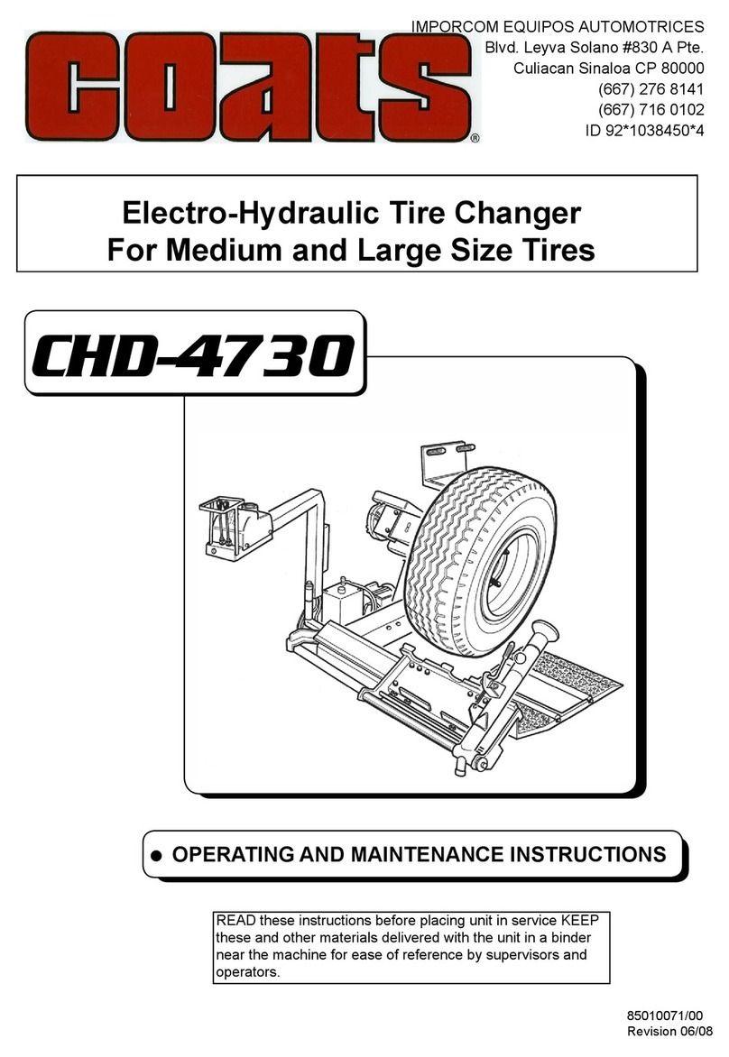
Coats CHD-4730W Manual

Parts Identification
The following pages include parts breakdowns with exploded view illustrations to help with ordering replacement
or spare kits. Assemblies are noted where it is recommended that individual parts not be ordered separately. Note
that the parts view illustrations are for multiple models and not all parts shown are on all models. Every effort is
made to supply accurate exploded views, however, due to interim changes in manufacturing operations, some
units may not be exactly as illustrated.

• COATS Wheel Balancer COATS Wheel Balancer •
Item Part No. Description
1 *84399827 SCREW M8x20 8.8
2 *84399829 WASHER 8 (8,4x16x1,5)
3 *86618196 SUPPORT
4 *83010283 HANDLE D.25 M10
5 *83009557 1/4” CARRIAGE HOSE L=2700
6 *84399953 SCREW 10x16
7 *83009566 POLYGROOVED RUBBER
3mm 395x195
8 *87918195 S.554 FRAME
9 *82109519 BEAD LOOSENER ARM PIN
10 *83001067 WASHER
11 * 84399302 SCREW 14x30 8.8
12 *87918194 ARM
13 *82409525 BRACKET
14 *84399966 SCREW M10x20 - 8.8
15 *84399945 SCREW M16x100 8.8
16 *84399828 WASHER 16 (17x30x3)
17 *84399963 SELF-LOCKING NUT M16
18 *86609462 LONG CYLINDER D.50 C=600
19 *84199249 1/4” UNION NUT
20 *84399256 WASHER 1/4” D.13x19x1,5
21 *83009544 TOOL-HOLDER SHAFT
22 *82109517 CARRIAGE
23 83018643 CARRIAGE SLIDING SHOE
24 83019036 SCRAPER 20x20
25 *84399951 SCREW 10x35 8.8
26 *84399228 SCREW 10x25 8.8
27 *84399378 WASHER D.10 (10,5x21x2)
28 *84399967 NUT M10
29 *84398849 SCREW M10x16
30 *86618193 FOOTBOARD
31 *84294232 ROLLER D.48 L=400
32 *84399295 NUT M16
33 84299251 ROLLER
34 *84399192 SPLIT PIN D.4x36
35 *84399813 WASHER 20 (21x37x3)
36 *83001039 ROLLER
37 *86618140 TOOL-HOLDER
38 83000114 BEAD LOOSENER SPRING
39 *82109539 HOOK
40 *83001031 CAM
Item Part No. Description
41 *84397334 SCREW 18x65 8.8
42 *84399316 SELF-LOCKING NUT M18x1,5
43 *84399228 SCREW 10x25
44 *84399967 NUT M10
45 *84399323 ELASTIC PIN D.6x18
46 *83001030 LEVER
47 *83001028 CONNECTING ROD
48 *82009977 TOOL-HOLDER GROUP
49 *84199145 STUD BOLT 1/4”
50 *83009556 1/4” CARRIAGE HOSE L=2100 PVC
51 *84297550 HANDLE D.28
52 *84399297 SCREW 8x130
53 83001038 SPRING
54 *83018125 EJECTOR
55 *84399903 WASHER 4 (4,5x12x1,5)
56 *84398945 SELF-TAPPING SCREW 4x12,6
57 *83001029 BOLT
58 *84399322 ELASTIC PIN D.8x32
59 83001040 SPRING
60 *84399321 ELASTIC PIN D.10x20
Frame Frame

• COATS Wheel Balancer COATS Wheel Balancer •
Item Part No. Description
1 *84298972 KNOB
2 *82109538 WHEEL CHUCKING RING NUT
3 *83009541 OVERSIZE CONE D.200-300 ALUM.
4 *83009540 SMALL CONE D.95-210 - ALUMIN.
5 *83009542 FLANGE D.200-280 - ALUM - MODEL 4730
*83012831 FLANGE - MODEL 4730W
6 *83019121 DRIVE PIN D.16 L=73
7 *82109521 CHUCK
8 *84294149 HANDWHEEL
9 *83018781 DRIVE PIN
10 *84398659 BELLEVILLE WASHER 12,2x28x1,5
11 *84399969 NUT M10
12 *82113879 FLANGE STIFFENER
13 *84399329 SCREW 10x40 8.8
14 *84398957 SCREW 10x60 8.8
15 *84399969 NUT M10
16 *83009523 CHUCK FRONT RING NUT
17 *84399378 WASHER D.10 (10,5x21x2)
18 *83001056 SPACER 81x105x0,5
19 *84297195 O-RING 181 (79,33x5,23)
20 *83009524 CHUCK REAR RING NUT
21 *84399956 SCREW 10x25 12.9
22 *83009629 GROOVED JOINT
23 *83009628 CHUCK SHAFT
24 *84399302 SCREW 14x30 8.8
25 *84398807 WASHER 14 (15x28x2,5)
26 *84399121 SCREW 6x6
27 *84399377 SCREW 10x30
28 *83018210 CHUCK FLANGE RUBBER PROTECTION
29 *83018209 CHUCK RUBBER PROTECTION
30 *84399971 SELF-LOCKING NUT M10
31 *84399837 SCREW 8x20
Self-Centering Chuck Self-Centering Chuck

• COATS Wheel Balancer COATS Wheel Balancer •
Item Part No. Description
1 *86618202 TANK
2 *86618204 TANK COVER
3 *84196472 MALE PLUG 1/4”
4 *84594305 MOTOR 3PH 200-240/345-415V.50/60HZ B5
5 *84198598 COPPER WASHER 3/8” 17x23x1,5
6 *84197600 UNION 3/8”
7 *86609461 CYLINDER D.50 C=250
8 *83009558 HOSE 1/4” L=2800
9 *84199250 UNION BOLT 1/4”
10 *84399256 COPPER WASHER 1/4” D.13x19x1,5
11 *83010651 OIL LEVEL PLUG 1/2” L=180
12 *84197240 90’’ UNION MF 3/8”
13 *84197239 SPACER 3/8”
14 *84197241 OIL FILTER 15 *4197873
16 *83009760 ELASTIC JOINT D.24
17 *84399121 HOSE 3/8” L=340
18 *84399956 SCREW 10x25
19 *84399829 WASHER 8 (8,4x16x1,5)
20 *84399299 SCREW 6x30
21 84398848 WASHER 6 (6,6x18x1,5)
22 *84197872 FLANGE GR.80 D.200 HL5L
23 *84197621 UNION 3/8”
24 *84399969 NUT M10
25 *84399786 SCREW 10x30
26 *84399827 SCREW 8x20
27 *84399998 WASHER 6 (6,4x12x1,6)
28 *84399976 NUT M8
29 82010985 REDUCTION GEAR
30 *86609531 SUPPORT
31 *86618198 MOTOR SUPPORT
32 *84594306 MOTOR 3PH 208-230V.50/60HZ Kw.1,1 B14 CSA
33 *83199596 GEARBOX PULLEY
34 *83003444 MOTOR PULLEY
35 84398826 SCREW 10x20
36 *83018181 BELT PROTECTIVE CASE
37 84294184 MEGADYNE BELT
38 *84399228 SCREW 10x25
39 *84399378 WASHER D.10 (10,5x21x2)
40 *83018173 EXHAUST PIPE 1/4” L=3000
41 *83018172 CONNECTING PIPE 1/4” L=3000
42 *84399969 NUT M10
43 *84399979 SEEGER RING D.30
44 *84398723 SCREW 6x12
45 *84197253 PUMP
46 *84396941 NUT M14
47 *84398802 NUT M14
Electric Motor and Hydraulic Power Unit Electric Motor and Hydraulic Power Unit

• COATS Wheel Balancer COATS Wheel Balancer •
Item Part No. Description
1 *86609533 CONTROL ARM SUPPORT
2 *84399329 SCREW 10x40 8.8
3 *84399378 WASHER D.10 (10,5x21x2)
4 *84399969 NUT M10
5 *83002601 WASHER D.10x45x4
6 *83002311 WASHER D.10x45x4
7 *84399228 SCREW 10x25 8.8
8 *86609534 CONTROL ARM
9 *83000069 CUP RING
10 *84299984 GREASE CUP
11 *86609781 CONTROL ARM COVER
12 *84399998 WASHER 6 (6,4x12x1,6)
13 *84399300 SCREW M6x12 8.8
14 *83009537 CONTROLS COVER
15 84595327 20A INVERSER
16 84597862 ISWITCH 3x12A
17 *84594177 OVERLOAD CUTOUT (230V - 60Hz)
*84597268 OVERLOAD CUTOUT (400V - 50Hz)
18 *84597276 OVERLOAD CUTOUT CASE
19 *83000174 REVERSER COVER
20 *84399885 SCREW TC 4x25
21 *84399996 NUT M4 6S
22 *86609973 REVERSER CONTROL LEVER
23 *84297981 KNOB
24 *84397178 SCREW 3x10 12.9
25 *84399903 WASHER 4 (4,5x12x1,5)
26 *84399121 SCREW 6x6
27 *84197349 HYDRAULIC DISTRIBUTION UNIT
28 *84398620 SCREW 6x45 8.8
29 *84399889 NUT M6
30 *84197330 3/8” UNION NUT
31 *84198598 COPPER WASHER 3/8” 17x23x1,5
32 *84199249 1/4” UNION NUT
33 *84399256 WASHER 1/4” D.13x19x1,5
34 *84199145 STUD BOLT 1/4”
35 *84398904 SCREW TSP 4x25 4.8
36 *83001976 PLASTIC RING
37 *83199628 BRUSH
38 *86611746 LEVER COVER
39 *84399229 SCREW TE M6x45 8.8
40 *86611747 LEVER COVER
41 *84597268 OVERLOAD CUTOUT
Control Device Control Device

• COATS Wheel Balancer COATS Wheel Balancer •
Item Part No. Description
1 *83030912 TUBELESS ROLLER SHAFT
2 *84394647 STEEL SHIM 52x65x1
3 *83018066 TYRE SUPPORT
4 *83018067 BEAD LOOSENER ROLLER
5 *84398880 SPRING PIN 4x12
6 *83018119 WASHER
7 *84399302 SCREW 14x30
9 *89218165 432/07 ROLLER FOR TUBELESS TIRE
10 *84397504 SCREW 12x30
11 *82110827 SUPPORT
13 *83010831 PIN
14 84396915 RING 41x52Ex0,5 (3)
15 *82019102 BEAD LOOSENING DISC
16 *82009782 PLIER
17 *84396916 SELF-LOCKING NUT 27x3
18 *84398657 NUT M12
19 *82110836 SHORT MOUNTING TOOL
20 *83010841 SPRING CONNECTION
21 83001266 SPRING D.18 L=72
22 *83000108 SPACER 12x18x11,5
23 *82019650 PLIERS
24 *83001304 SCREW ANCHOR
25 *83001303 COUPLING
26 *84399121 SCREW 6x6
27 89299271 138/90 PLIERS FOR ALLOY RIMS
28 *83001061 LEVER
29 *86601002 BEAD LIFTING LEVER
30 *82010852 DOUBLE TOOL
32 *84396878 STEEL SHIM 12x25x0,5
33 *82033519 CLAMP SPACER
34 84294076 BALL GRIP THP 25 M.6x15
35 87019167 CLAMP SUPPORT SPACER
Accessories and Options Accessories and Options

OPERATING AND MAINTENANCE INSTRUCTIONS
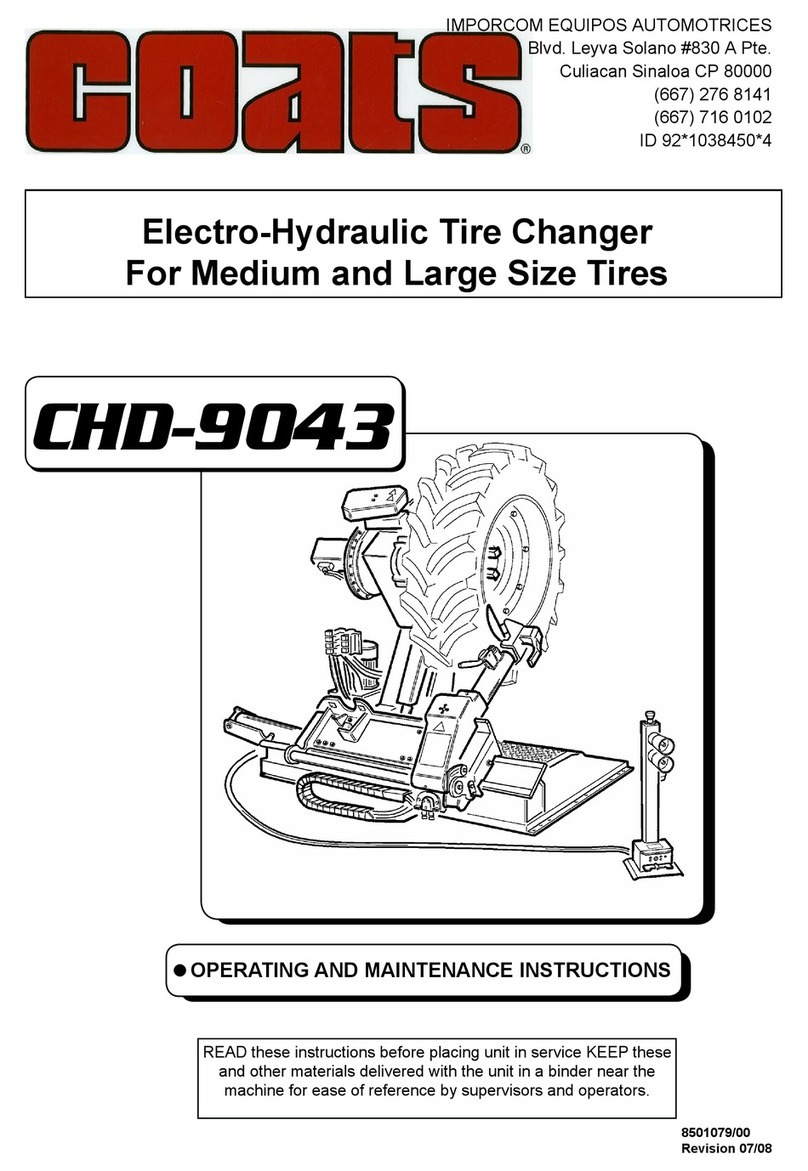
Electro-Hydraulic Tire Changer
For Medium and Large Size Tires
CHD - 4730 - 4730W
READ these instructions before placing unit in service KEEP
these and other materials delivered with the unit in a binder
near the machine for ease of reference by supervisors and
operators.

1. INTRODUCTION
Thank you for purchasing one of our tIre-changers: This label has been specically designed to t and remove truck, bus and commercial vehicle
tires, with rims from 14” to 26” and maximum 47” (1200 mm) diameter. Any other use is improper and therefore not authorized.
The machine has been constructed to the best quality principles.
This manual has been made in order to supply the owner as well as the user with the basic instructions for a correct use of the tire-changer.
That’s the only way to grant the respect of the conditions necessary to work safely and also grant the best efciency and a long life to the machine.
Read this manual with the utmost care before using the tire-changer.
Keep this manual as well as all the supplied technical literature in a safe place close to the tire-changer so as to help the users to consult it whene-
ver necessary.
The technical literature is an integral part of the machine and it must always follow the product, during it’s entire life
These instructions are intended for trained users and professionals, having a certain level of knowledge in the matter. We have therefore avoided
to describe each single operation. Always avoid to carry out operation beyond your own cability. In case of any need of assistance, your service.
Follow the directions given by this guide carefully.
Any other use not described is to be considered as
improper and irrational, and thus it will be under the
whole responsibility of the operator.
The manufacturer shall not be liable for any injury to persons or damage to things caused by improper use of this machine.
1.1. Technical data

Fig.2
11
12
5
16
17
10
9
8
76
7A
6A
19
20
20
2
4
3
1
14
15
13
10
18
17
1. ON/OFF main switch
2. Clamping chuck control lever for rotation
CLOCKWISE/COUNTERCLOCKWISE rotation
3. Control lever for FORWARD/BACKWARD
Movement of tool-arm carriage
4. Control lever for UP/DOWN movement of clamping chuck arm
5. Controls stand
6. The clamping xed ange plate
6A Tire clamping movable ange plate
7. 4”-8” (100 ÷ 200 mm.) clamping cone
7A 200 ÷ 300 mm. locking cone
8. Locking hub nut
9. Mounting/demounting tubeless roller
10. Wheel support sliding ramp
11. Tool tray
12. Motor belt protective cover
13. Bead loosening disk (optional)
14. Fingen tool (optional)
15. Tool lock/release pin
16. Carriage
17. Tool-arm
18. Arm locking handle
19. Movable ange locking knob
20. Anti rotation pin
21. Liofting hook
2. DESCRIPTION OF THE MACHINE
21

3. GENERAL
3.1_General SAFETY rules
The tire-changer has been designed and manufactured exclusively for mountig/demounting tires onto/from the rims.
Any other use is to be considered improper. The manufacturer cannot be held responsible for any damage or injury caused by an improper use.The
machine may only be used by adult staff, previously authorized and trained.
Any tampering or modication, relieves the manufacturer of eventual damages referred to the mentioned actions.The tire-changer is equipped with
instruction and warning stickers designed and produced to last over time.
In case they get damaged or destroyed the user must require the manufacturer for replacing them, using #2019026 for reference. Any work on the
electrics, however small, must be carried out by qualied staff according to the current national regulations.
Only use Original spare parts listed in the Spare Parts Catalogue. The manufacturer cannot be held responsible for any claim caused by use of
non-original spare parts.
The tire-changer may be equipped with accessories, which must be listed and approved by the manufacturer. The manufacturer cannot be held
responsible for any injury or damage deriving from unapproved accessories.
It is forbidden to use the tire-changer in places having potentially explosive atmosphere.
OIL
AGIP OSO
46
MAX.
130 bar
(1885 PSI)
Flow 4.2 lt./min
Max Press. 130 Bar
Tank Capacity
5,2 lt.
In case the warning labels are unreadable or have been removed, it is necessary to replace them immediately. Do not use
the tire-changer if one or more labels are missing. Do not add any object which could prevent the operator’s from seeing the
labels. When ordering the labels always use the ref. code given in this diagram as a reference
WARNING

4.
TRANSPORT, MOVING AND STORING
The machine is delivered in a cardboard box on wooden pallet.
The machine must be transported in its original package and kept in the position shown on the package itself.
Move the machine by means of a fork-lift truck having enough loading capacity. Fit the forks as shown in g.4
Should the machine be temporarily stored, make sure that the storing place has the following requirements:
- Max. relative humidity: 95%
- Temperature: min. 32°F (0°C); max. 131°F (55°C)
5. UNPACKING
After having removed the package, make sure that the tire-changer has not suffered any damage during transportation. Take out the standard deli-
vered accessories too.
The package units must be stored in a safe place, out of children’s reach, being them a possible source of danger.
Keep the packing for possible future transport
Unpack the machine by using the related hook for lifting it. Originally placed on the main chassy, close to the clamping chuck arm (21, g. 2). During
this phase pay attention not to damage the control unit, which is not xed.
After placing the machine in its installation position, always remove the liftinf hook, which may interfere with regular oparation.
55,1 inch(1400 mm)
29,5 inch(750 mm)
60 inch (1520mm)
Fig.4
1092 lbs
(Kg. 495)

Chose the installation site according to the current rules on Safety at Work.
The automatic tire-changer needs to be connected to the electric network. It is therefore advisable to install it in a place where this connection is
available.
Moreover, the installation space must allow the operator to use the machine and all its components without any restriction (see dimensions given in
g. 5) In case of installation outdoor it is necessary to protect the machine against rain by means of any kind of footing.
6. INSTALLATION
6.1_Installation site
IT IS FORBIDDEN to use the machine in explosive at-
mosphere
Fig.5
The tire-changer must be installed on a level concrete oor at least 6” (15 cm) thick, with a minimum concrete quality of B25 in compliance with DIN
1045 requirements (foundations). See the diagram herebelow.
If a oor of this type is not available on site, a suitable foundation under the bearing points must be provided. The installation surface must be levelled
in all directions.
Inclinations up to 0,25% relative to the horizontal can be compensated using suitable shims, wedges or the alike.
When working with wheels, whose weight is higher than 2,204 lbs (1,000 kg)., it is necessary to fasten the tire-changer
to the oor by means of proper anchor bolts.
Use a Ø 16 widia bit to drill the oor to a depth of at least 0.63 inch (130 mm)., passing through the holes already provided in the base frame.
If there is an additional oor covering (B), or if shims or wedges are necessary for levelling (C), longer anchor bolts must be used.
Place an anchor bolt into each hole.
Make always sure that the bolts extend at least 4.90” (125 mm) into the concrete slab, as shown in g. 6
Tighten the anchor bolts.
GROUND
REINFORCED CONCRETE
ELECTRO-WELDED GRID
PEBBLE GRAVEL
Foundationsdimensions inch (cm). Concrete
quality
Min. pressure
resistence
Length Width Thickness
B25 937 lbs/sqft
(425 Kg / cm
2
)
78,74
(200)
64,5
(164)
5,9
(15)

All the operations on electrics must be carried out by proffessional electrician. Before making electric hoop up, check to make
sure the main voltage corresponds to that pronted on the voltage tag (attacched to the cord near the plug)
It is absolutely essential that:
-the system is equipped with a good grounding circuit
- protected against overcurrents with fuses or automatic magneto-thermic switch
Note the required power drow as highlighted on the data plate xed to the tire charger. Make shure the shop electric wiring circuit is dimensioned
sufciently to carry this.
The voltage drop with full load must never exceed 4% of the voltage nominal value shown by the data plate.
Connect the tire-changer to the power supply network, switch it on and check the motor running direction (same as indicated by the arrow – g.9).
In case of opposite running direction, it is necessary to have two wires inverted in the plug.
The motor run made in the opposite direction, if longer than a few seconds, can cause irreparable damages to the motor itself.
Remarks: both electrical motor and hydraulic unit motor are equipped with an overload cutout (g.10) against overloads.
6.3_Electrical connection.
6.2_Parts assembling
Mount the control stand by tting the hose in its support and x as shown in g.7 Mount the tool tray and fasten it by means of the two bolts shown
in g.8
3,93
1,96
5,90
3,93
3,93
inches ø 0,31
inches
Ø 0,7
Ø 0,7
Ø 0,7
MAX 0,25%
4,9
4,9
4,9

Fig.9
Fig.7
Fig. 8
Fig.10
6.4_Operation test
Before working with tire-changer it is necessary to carry out some tests to check the correct operation and installation as well.
All the following operations must be carried out with the tool-arm (17 g 2) set in non-working position.
Press handle 18 to unlock the arm. Pull it and tip it in its non working position. Refer to g. 11 for carrying out the running test.
Switch on the main switch (1) on control panel. The machine must turn on.
Set lever (2) in the position indicated by the continuous arrow to let the clamping (6) turn COUNTERCLOCKWISE.
Set lever (2) in the position indicated by the dashed arrow to let the ange (6) turn CLOCKWISE.
Set lever (3) in the position indicated by the continuous arrow to move the carriage (16) AWAY FRON THE SPINDLE.
Set lever (3) in the position indicated by the dashed arrow to move the carriage (16) FORWARDS THE SPINDLE.
Set lever (4) in the position indicated by the continuous arrow to LOWER the spindle.
Set lever (4) in the position indicated by the dashed arrow to LIFT the spindle.
When the spindle carrier arm is lowered, there is always a potential for crushing anything in its movementrange. Always work
fron the position given in the intructions keeping well out of worning range of the various moving arm

Fig.11
11
12
5
16
17
10
9
8
76
7A
6A
19
20
20
2
4
3
1
14
15
13
10
18
17
7. OPERATION
7.1_Notes for operation
The non-observance of instructions and warnings can cause serious injuries to the operator or third persons.
Do not use the machine before having read and understood all the instructions given in this manual.
Keep unauthorized persons far from the working area.
Make always sure to respect all the rules as previously recomended in the manual, when installing the tire-changer installation. All the operators
must be suitably trained before using the machine. Never leave objects on tire-changer, which during the working phase could represent a source of
potential hazard.
Do not modify or tamper with the tire-changer. During working phase, draw up long hair, DO NOT wear large clothes, ties, chains, rings, watches,
which could be caught by moving parts.
Keep this manual in a safe place and do not forget to check it.
To stop tire-changer in emergency case:
- Switch off the main switch to “0”
- Disconnect the electric plug
Only use original accessories and spare parts.

7.2_Rim clamping
Tip the tool-arm (17, g. 11) in its non working position. By means of the lever (3) move the ramp (10) away from the spindle and place the tire as-
sembly in vertical position over the sliding ramp.
While clamping, make sure that the rim is well positionned on the ange plate, so as to prevent the tire from rolling down.
By means of the lever (4) lift or lower the spindle arm until the ange plate is best centered to the rim.
To facilitate this operation, it is advisable to keep the anti-rotation ange pin (20) in the lower part of the rim.
Let the anti-rotation pin (20) match with one of the lug holes of the rim as indicated in g.15 Place a clamping cone with suitable size in teh rim center
hole. Set the locking hub nut (8) on the shaft and lock everything by turning the hub nut as far as it goes.
The machine has been designed to work on 14”-26” tyres mounted on rims having central hole of min. 4” (100 mm.) – max. 12” (300 mm.) diameter.
According to the kind of rim, it is therefore, necessary to act in different ways to lock it onto the ange.
RIMS WITH CENTRAL HOLE Ø 4”- 8” (100 ÷ 200 mm)
To clamp these rims, use xed ange plate (A g. 13) together with small cone (B Fig.12)
RIMS WITH CENTRAL HOLE Ø 8” - 12” (200 ÷ 300 mm)
To clamp these rims, mount big ange plate (C, g. 13) and use big cone (D Fig. 14)
Fig.12 Fig.13
Fig.14
A
B
C
A
C
D
20
20
Fig.15
20
8
DANGER! POTENTIALLY HAZARDOUS OPERATION!
Do it manually only if you are certain you can keep the tire assembly balanced. For large and heavy tyres
an adequate lifting device must be used.

7.3.1_ Bead loosening and tire removing with ROLLER TOOL
1) Make sure that the tyre is clamped and deated.
2) Tip the tool-arm (17) in its working position, by lowering it until it gets hooked properly.
Always check that the arm is properly hooked to the carriage.
3) By means of levers (3) and (4) make the roller tool position close to the rim edge and outsideface of the tire(g.16)
4) Make the tire rotate and, at the same time, press the roller against the tire bead at brief steps.
5) Go on until the bead is completely detached.To facilitate the operation, when the tire is turning, grease the bead and the rim edge all around
(g.17)
Pay attention not to put ngers between tire and tool. In order to avoid any possible risk, turn CLOCKWISE when operating on the
outer face of the tire, and COUNTERCLOCKWISE when operating on the inner face.
6) Move the tool-holder away from the rim, release the anloock, lift the arm out of work, slide it towards the spindle and lock it in its second working
position
DO NOT keep your hands on the tool when setting it in working position so as to avoid any possible crushing between tire and
tool.
7) Repeat the operations (3), (4) and (5) above until the second bead is completely
detached (g.18)
8) Go ahead pushing the tire, it comes completely off the rim (g.19)
7.3 TUBELESS TIRE
DANGER!
When the beads come off the rim, the tire will fall. Check to make sure there are no by-standers in the work
area.

Fig.17
Fig.19
Fig.16
17A
18
17A
17B
7.3.3_Bead loosening and demountig with DOUBLE TOOL (optional # 9209552)
1) Make sure that the tire is clamped and deated.
2) Tip the tool-arm (17) in the working position, by lowering it until it gets hooked on the carriage.
Always check that the arm is correctly hooked to the carriage.
3) By means of levers (3) and (4) move the tool arm close to the outside rim edge and outside face of the tire.
(double tool must be locked by handle 15,g. 11, with disk facing the spindle)
4) Rotate the tire and, at the same time, move the disk forward against the tire bead at brief steps (g.20)
5) Go on until the bead is completely detached. To facilitate this operation, when the tire is turning grease the bead and the rim edge all around.
Pay attention not to put ngers between tire and tool. In order to avoid any possible risk, turn CLOCKWISE when operating on the
outer face of the tire and COUNTERCLOCKWISE when operating on the inner face.
6) Move the tool-arm away from the rim, release the lock, tip the arm into its non working position, slide it towards thr spindle and lock it in its second
working position.
7) Unlock and turn the tool 180°, to have the disk facing the inside face of the tire (g. 21)
17B
Fig.18

DO NOT keep your hands on the tool when setting it in working position so as to avoid any possible crushing between tire and
tool.
8) Repeat the operations of points (5) and (6) until the second bead is completely detached (g.21)
9) Go ahead on pushing the tire it comes completery off the rim (g.22)
Fig.20 Fig.21
Fig.22
1
2
34
15
18
7.3.4_Tire mounting with roller tool.
1) Make sure that the rim is clamped properly (see paragraph on “Rim Clamping”).
2) Lubricate both beads and the rim with tire manufacturer recommended lubricant.
3) Attach the g-clamp to the outside edge of the rim. at its highest point.
DANGER!
When the beads come off the rim, the tire will fall. Check to make sure there are no by-standers in the work
area.
CAUTION!
Make sure the g-clamp is rmly attached to the rim.
This manual suits for next models
1
Table of contents
Other Coats Tyre Changer manuals
Popular Tyre Changer manuals by other brands

Fasep
Fasep RGU588E Installation, use and maintenance guide

Cormach
Cormach LIGRO Use and maintenance manual

Mondolfo Ferro
Mondolfo Ferro AQUILA RAPTOR Operator's manual

GIULIANO
GIULIANO S 226 Installation, operation & maintenance manual

Hofmann
Hofmann monty 1520m quick start guide

Hofmann
Hofmann monty 1675 smartSpeed Operation manual