4
NOTE: Set-ups and adjustments will be made in subsequent steps, this will require
access to both the front and rear of the unit. Plan the installation and wiring
accordingly.
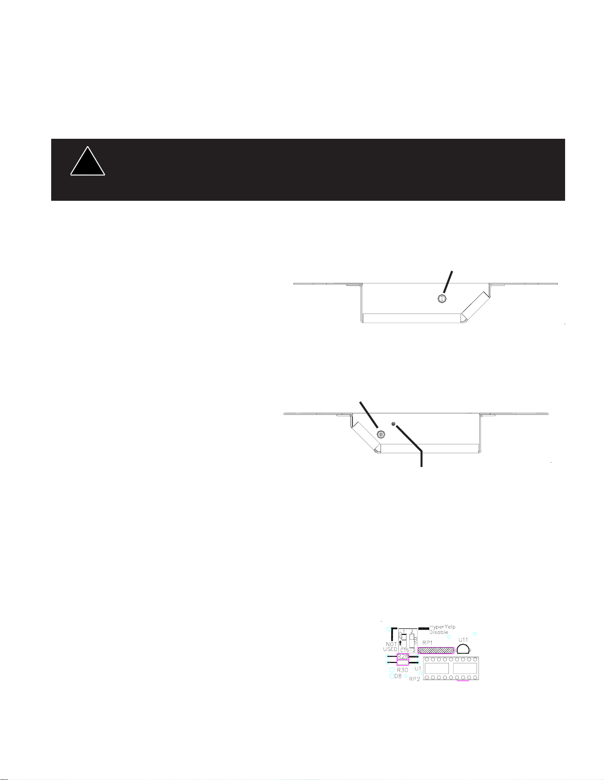
Connections (see Figure 1), motorcycle wiring harness.
Speaker - Connect to 100W ( 11 ohm ) speaker leads.
IGNITION - Connect (18 AWG wire) to the motorcycle's ignition switch so that +12VDC is applied to
this wire only when the ignition switch is in the ON position.
+12V - Connect (14 AWG wire) to a positive +12 volt DC source. It is recommended that the user
protect this wire with a 10 Amp fuse or circuit breaker located at the source.
CONNECTION OF A 58 WATT SPEAKER TO THE SPKR TERMINAL WILL CAUSE THE
SPEAKER TO BURN OUT, AND WILL VOID THE SPEAKER WARRANTY!
The sound projecting opening should be pointed forward, parallel to the ground, and not obstructed
or muffled by structural components of the vehicle. Concealed or under-hood mounting in some
cases will result in a dramatic reduction in performance. To minimize this eduction, mount the
speaker so the sound emitted is projected directly forward and obstruction by vehicle components
such as hoses, brackets, grille, etc. is minimized.
Electromechanical sirens and electronic siren speakers should be mounted as far from the
occupants as possible using acoustically insulated compartments and isolation mountings to
minimize the transmission of sound into the vehicle. It may be helpful to mount the device on the
front bumper, engine cowl or fender; heavily insulate the passenger compartment; and operate the
siren only with the windows closed.
Each of these approaches may cause significant operational problems, including loss of siren
performance from road slush, increased likelihood of damage to the siren in minor collisions, and
the inability to hear the sirens on other emergency vehicles.
APPROPRIATE TRAINING OF VEHICLE OPERATORS IS RECOMMENDED TO ALERT THEM
TO THESE PROBLEMS AND MINIMIZE THE EFFECT OF THESE PROBLEMS DURING
OPERATIONS.
Larger wires and tight connections will provide longer service life for components. For
high current wires it is highly recommended that terminal blocks or soldered connections be used
with shrink tubing to protect the connections. Do not use insulation displacement connectors (e.g.
3M®) Scotchlock type connectors). Route wiring using grommets and sealant when passing
through compartment walls. Minimize the number of splices to reduce voltage drop. High ambient
temperatures (e.g. underhood) will significantly reduce the current carrying capacity of wires,
fuses, and circuit breakers. Use "SXL" type wire in engine compartment. All wiring should
conform to the minimum wire size and other recommendations of the manufacturer and be
protected from moving parts and hot surfaces. Looms, grommets, cable ties, and similar
installation hardware should be used to anchor and protect all wiring.
Fuses or circuit breakers should be located as close to the power takeoff points as possible and
properly sized to protect the wiring and devices. Particular attention should be paid to the location
and method of making electrical connections and splices to protect these points from corrosion
and loss of conductivity. Ground (Earth) terminations should only be made to substantial chassis
components, preferably directly to the vehicle battery.
The user should install a circuit breaker sized to approximately 125% of the maximum Amp
capacity in the supply line to protect against short circuits. For example, a 30 Amp circuit breaker
should carry a maximum of 24 Amps.
DO NOT USE 1/4" DIAMETER GLASS FUSES AS THEY ARE NOT SUITABLE FOR
CONTINUOUS DUTY IN SIZES ABOVE 15 AMPS. Circuit breakers are very sensitive to high
temperatures and will "false trip" when mounted in hot environments or operated close to their
capacity.
!
WARNING!
!
WARNING!