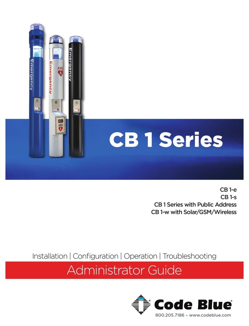
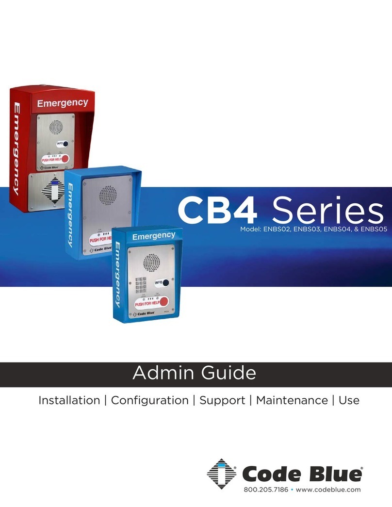
Code Blue CB 1 Series Manual

CB 1 Series
page 2 of 31
Administrator Guide
WARNING
ONLY QUALIFIED PERSONNEL SHOULD INSTALL THESE UNITS. THE INSTALLATION
SHOULD CONFORM TO ALL LOCAL CODES. IN SOME COUNTRIES, A CERTIFIED
ELECTRICIAN MAY BE REQUIRED.
NOTICE TO USERS
Copyright © Code Blue Corporation. All rights reserved. This guide or software
described herein, in whole or part, shall not be reproduced, translated or reduced to any
machine-readable form without prior written approval from Code Blue Corporation.
CODE BLUE CORPORATION PROVIDES NO WARRANTY WITH REGARD TO THIS
GUIDE, THE SOFTWARE OR OTHER INFORMATION CONTAINED HEREIN AND HEREBY
EXPRESSLY DISCLAIMS ANY IMPLIED WARRANTIES OF MERCHANTABILITY OR
FITNESS FOR ANY PARTICULAR PURPOSE WITH REGARD TO THIS GUIDE, THE
SOFTWARE OR SUCH OTHER INFORMATION. IN NO EVENT SHALL CODE BLUE
CORPORATION BE LIABLE FOR ANY INCIDENTAL, CONSEQUENTIAL, OR SPECIAL
DAMAGES, WHETHER BASED ON TORT, CONTRACT, OR OTHERWISE, ARISING OUT
OF OR IN CONNECTIONS WITH THIS GUIDE, THE SOFTWARE OR OTHER
INFORMATION CONTAINED HEREIN OR THE USE THEREOF.
Code Blue Corporation reserves the right to make any modifications to this guide or the
information contained herein at any time without notice. The software described herein
may also be governed by the terms of a separate user license agreement.
Code Blue® is a registered trademark of Code Blue Corporation. The names of actual
companies and products mentioned herein may be the trademarks of their respective
owners.
GU-157-FF
Code Blue • 259 Hedcor Street • Holland, MI 49423 USA • 800.205.7186 • www.codeblue.com

CB 1 Series
Table of Contents
Administrator Guide
Section
Section Title
Page #
2
Introduction
4
CB1 Model Photos
5
3
Safety Information
6
4
Installation Instructions
7
Tools Required
7
Getting Started
8
Anchor Bolt Kit
9
Deck Mount Kit
10
Base Gasket
11
Overhead Camera Mount
12
Equipment Ring
13
Dome Top
14
S-1000 & S-1050 Strobe/Beacon
15
5
Programming
16
6
Power Requirements
17
7
Wiring Diagram
21
100-240 AC / DC or 24V AC @ 60 Watt or 24V DC
21
PoE DIN Rail Power System | 48V DC 12.96w or 25.5w
22
NightCharge® 120-240V AC @ 5 Amps w/ Area Light | 12VDC 10
Amps
23
NightCharge® 120-240V AC @ 3 Amps NO Area Light | 12VDC 10
Amps
24
120-277V AC DIN Rail Power w/ 150W Audio Paging | 12 or 24V
DC 10 Amps Max
25
Multi-Tap Transformer (Power Brick) 110-347VAC
26
8
Locating Unit Serial Numbers
27
9
Maintenance Schedule
28
10
Warranty
30
11
Download Information
31
12
Legal and Regulatory Information
32
GU-157-FF page 3 of 31
Code Blue • 259 Hedcor Street • Holland, MI 49423 USA • 800.205.7186 • www.codeblue.com

2 Introduction
GU-157-FF
CB 1 Series
Administrator Guide
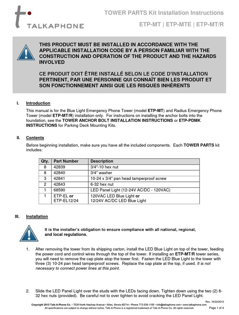
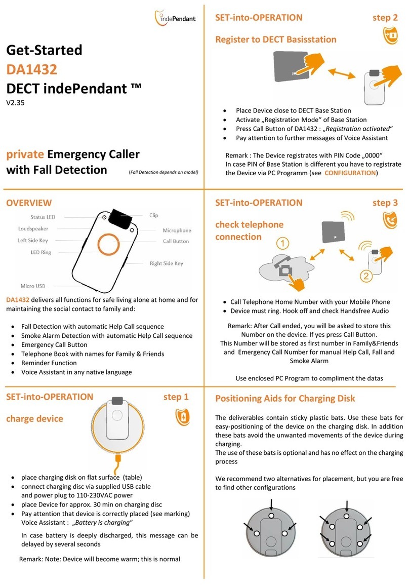
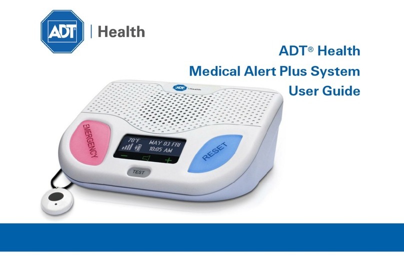
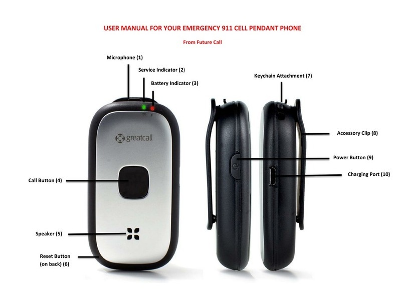
Thank you for choosing the CB 1 Series for your Code Blue application.
The CB 1 Series of products are the original Code Blue pedestal units that set the industry
standard for rugged construction, full feature availability and high visibility. The CB 1 Series is
easily recognized throughout a full 360-degree area. The user friendly lighted faceplate and the
integral area light ensure rapid location in an open environment. The high output strobe is easily
identifiable by security when activated.
The CB 1 Series is an excellent choice for walkways, parks, college and commercial campus areas,
open landscape areas and anywhere a freestanding pedestal unit is required.
The exclusive analog InterAct and VoIP speakerphones are designed for maximum reliability,
vandal resistance, auxiliary functions, mass notification control, and fault monitoring and
reporting capability. (See IA4100 or LS1000 guides for more information.)
Our unmistakable craftsmanship makes our Help Points® the most rugged on the market,
withstanding the punishment of natural and man-made disasters. With durable construction, our
pedestal units can meet any requirement or purpose. CB 1 Series units have a rugged steel
construction, shatterproof Lexan Lens, industrial engineering grade reflective graphics and
weather, UV and graffiti resistant paint. They are illuminated by a high-powered, 270 lumens/92
candela LED blue beacon/strobe.
IP and analog phones
Low power consumption LED faceplate light
Long-life LED area light
NightCharge® & PoE power options
360° Audio Paging Speaker
Custom colors and graphics
Second Opening for camera, card reader, directory, & other customizable options
Overhead Camera Mounts
Mounting Rings
Other options include:
page 4 of 31
Code Blue • 259 Hedcor Street • Holland, MI 49423 USA • 800.205.7186 • www.codeblue.com

CB 1 Series
Administrator Guide
This guide contains all of the CB 1 Series information for the CB 1-e, & CB 1-s. This
guide contains a general overview of the CB 1 Series options and its application,
installation and wiring
CB 1-e CB 1-s CB 1-s with
Dual Faceplate
GU-157-FF page 5 of 31
Code Blue • 259 Hedcor Street • Holland, MI 49423 USA • 800.205.7186 • www.codeblue.com

Indicates a hazardous situation which, if not avoided, will result in
death or serious injury.
Indicates a hazardous situation which, if not avoided, could result in
death or serious injury.
CAUTION
Indicates a hazardous situation which, if not avoided, could result in
minor or moderate injury.
NOTICE
Indicates a situation which, if not avoided, could result in damage to
property.
IMPORTANT
Indicates significant information that is essential for proper product
functionality.
NOTE
Indicates useful information that helps get the most out of a
product.
3 Safety Information
HAZARD LEVELS LEGEND
CB 1 Series
Administrator Guide
WARNING
DANGER
Safety Instructions
Code Blue products shall be installed by trained professionals. The installation should
conform to all local codes. In some countries, a certified electrician may be required.
When transporting a Code Blue product, use the original packaging or equivalent to
prevent damage to the product.
Code Blue products shall be used in compliance with local laws and regulations.
Store the Code Blue product in a dry and ventilated environment.
Do not install the product on unstable brackets, surfaces or walls.
Use only applicable tools when installing Code Blue products.
Do not use chemicals, caustic agents, steel wool or aerosol cleaners other than those
tested and recommended by Code Blue.
Use only accessories that comply with technical specifications of the product. These
can be provided by Code Blue or a third party.
Use only spare/replacement parts provided by or recommended by Code Blue.
Transportation
When transporting a Code Blue product, use the original packaging or equivalent to
prevent damage to the product.
WARNING
NOTICE
NOTICE
GU-157-FF page 6 of 31
Code Blue • 259 Hedcor Street • Holland, MI 49423 USA • 800.205.7186 • www.codeblue.com

Tools Needed
CB 1 Series
Administrator Guide
4 Installation Instructions
GU-157-FF
All CB1 Units Require:
• Ladder to reach the top of the unit.
• Drill & Security Bit for removing & inserting security screws on
phone, dome top, & access door.
• 1-1/8” Socket set & extension
• Phillips and flat head screwdrivers
CB1 Units w/ NightCharge® Require:
• ½” wrench for NightCharge® batteries.
page 7 of 31
Code Blue • 259 Hedcor Street • Holland, MI 49423 USA • 800.205.7186 • www.codeblue.com

Important Notes:
Getting Started
CB 1 Series
Administrator Guide
EIA/TIA, ANSI, CSA and BICSI cabling or similar standards shall be adhered to
for proper operation of Code Blue communication devices connected to
copper or fiber infrastructures communications cable and electrical cable in
the same conduit is not an acceptable installation and shall not be supported.
Analog phones require a minimum of 23mA for proper operation (26-29mA
recommended).
Each analog speakerphone requires its own phone line or PBX extension.
Multiple units shall not be supported.
Speakerphones require programming before operation. Consult the
speakerphone’s Administrator Guide for instructions.
If you are installing IP speakerphones, please read the appropriate manuals
and consult with your Network Administrator.
Size electrical wiring based on length of run.
GU-157-FF page 8 of 31
Code Blue • 259 Hedcor Street • Holland, MI 49423 USA • 800.205.7186 • www.codeblue.com

2. PULL WIRING
IMPORTANT:
1. FOUNDATION
Four 24-inch L-shaped anchor bolts and an aligning
template are supplied for anchoring the Code Blue
unit. The bolts should be set into the foundation so
that six inches are left showing above the finished
grade level. The anchor bolts should be aligned, using
the supplied template in such a way that the phone
faceplate on the unit face in the desired direction.
The foundation should be at least 24 inches in
diameter and to the correct depth for the frost line in
your area, with a mini- mum depth of at least three
feet (follow local building codes for foundations).
Electrical and telephone line conduit, with a maximum
combined diameter of four inches, should be run up
through the center of the foundation hole. A minimum
of four inches and a maximum of six inches of conduit
above the finished grade level is required. To ensure
proper grounding, a ½-inch x 8-foot copper rod should
be inserted in the center of the foundation and tied to
the steel pedestal.
A minimum of two feet of wire must be available from
the con- duit for electrical and communications wiring.
Anchor Bolt Kit Instructions
1.1 Run Conduit
1.2 Pour the Foundation
1.3 Set the Anchor Bolts in the Wet Foundation
2.1 Pull Power and Phone Line up through Conduits
• Wire gauge must be selected to meet code for voltage/current required for the product to
operate correctly: Minimum 14 AWG.
• Conduit used must comply to National Electrical Standards as observed locally.
NOTE: Follow all national and local codes governing this installation.
NOTE: Communications wire must be shielded phone line. The
phone line must be pulled into the unit using a separate conduit
from the power. Along with a service loop of wire, as noted by the
NEC standards.
CB 1 Series
Administrator Guide
GU-157-FF page 9 of 31
Code Blue • 259 Hedcor Street • Holland, MI 49423 USA • 800.205.7186 • www.codeblue.com

2. PULL WIRING
IMPORTANT:
1. DECK
FOUNDATION
Drill a fifth hole in the center to accommodate the conduit.
To prevent tampering, it is advisable to tack weld the
lower nuts to the threaded rod.
Drill four holes through the deck or floor for the four
3/4” threaded rods. The holes should be aligned, using
the tem- plate provided in such a way that the phone
faceplate on the unit will face in the desired direction.
Position the second plate working from below the deck.
Have another worker hold the upper plate and rods in place
from above the deck.
1.4.1 Place the second plate gasket and then the second
plate over the threaded rods.
1.4.2 Secure the second plate with nuts and washers pro-
vided. If required, readjust the nuts so that six inches of the
rods are above the top of the upper plate.
A minimum of two feet of wire must be available from the
conduit for electrical and communications wiring.
Position the first plate working from above the deck.
1.3.1 Thread a nut and washer on the end of each rod so
that approximately six inches extends beyond the base of
the washer.
1.3.2 Insert each rod through the top side of the plate, plate
gasket, and down through the four holes in the deck.
Electrical and telephone line conduit is run through the deck
and the center openings (two-inch diameter) of the upper and
lower deck plates. A minimum of four inches and a maximum of
six inches of conduit above the upper plate is required.
Deck Mount Kit Instructions
2.2 Conduit
1.1 Drill Deck Holes
1.2 Drill Conduit Hole
1.5 Secure Lower Nuts
1.3 Position Upper Deck Plate
1.4 Position Lower Deck Plate
2.1 Pull Power and Phone Line up through Conduits
NOTE: The top of the plate is the side with the tapered edge.
Wire gauge must be selected to meet code for voltage/current required for the product to
operate correctly: Minimum 14 AWG. Conduit used must comply to National Electrical Standards as
ob- served locally.
NOTE: Communications wire must be shielded phone line. The phone line must be pulled into the unit using
a separate conduit from the power. Along with a service loop of wire, as noted by the NEC standards.
CB 1 Series
Administrator Guide
GU-157-FF
SKIP if installation does not include a Deck Mount Kit
page 10 of 31
Code Blue • 259 Hedcor Street • Holland, MI 49423 USA • 800.205.7186 • www.codeblue.com
3. SECURE THE UNIT
1. SET THE NUTS AND WASHERS
2. SET UNIT UPRIGHT ON ANCHOR BOLTS
Set the gasket on the bolts and cut a small hole where the
conduit is located.
Stretch the screen tightly around the conduit pipe. Slide the
gasket over the bolts to the base of the unit.
Align the phone plate in the desired direction and lift the
Code Blue unit over the anchor bolts. The unit may be lifted
using the bracket on the inside of the unit.
After the foundation has set, screw one set of nuts, followed
by one set of washers, onto the anchor bolts. Set the nuts so
the lowest washer is about 2½ inches above the concrete at
an even height.
Access the mounting studs through the door on the side
of the unit.
Place the second washer on the anchor bolt and place the nut
on top.
Tighten the mounting nuts onto the anchor bolts. This may be
more convenient if a long socket (extension and universal joint)
is used to tighten the hardware.
Base Gasket Instructions
IMPORTANT: A ½-inch minimum
air gap is required between the
foundation and the unit to
prevent moisture problems.
IMPORTANT: Leveling the
bottom nuts is crucial to leveling
the unit.
A small error will be magnified
after installation.
Fasten
Place the base gasket
Use Access Door to reach mounting studs
Set the Code Blue unit on the anchor bolts:
Screw one set of nuts and washers onto the anchor bolts:
*For an extra-strong seal, a bead of silicone caulk can be put on the gasket from bolt
hole to bolt hole before setting the gasket into place and around the conduit.
CB 1 Series
Administrator Guide
GU-157-FF
Note that the unit weighs approximately 200-400 pounds.
Use appropriate lifting materials and methods to avoid
possible injury and/or damage.
To accomplish this, use a small level and check from front to
back, side to side, & diagonally. These nuts are NOT
adjustable after the unit is in place.
The bottom edge of the Code Blue unit will be 1/2" above
the concrete when in stalled.
page 11 of 31
Code Blue • 259 Hedcor Street • Holland, MI 49423 USA • 800.205.7186 • www.codeblue.com
Camera and wiring is installed into the male 1 ½ NPT.
2.1 Locate and install the three ½ x 1-inch hex Allen screws from
the inside of the mounting ring. Be sure the Allen screws do not
extend beyond the outside of the ring.
2.2 Install the camera mount on top of the unit. Rotate to
desired position.
2.3 Verify camera mount is evenly positioned to ensure gasket seal
is seated appropriately 360 degrees.
4.1 Remove the clear Lexan dome from the black metal casting.
4.2 The casting, complete with strobe, should be brought to the
top of the unit (Overhead Camera Mount) where the wiring will be
connected (see wiring instructions).
4.3 After the wiring is complete, set the casting on top of the unit
and fasten the casting to the Overhead Camera Mount by reach-
ing through the casting openings and tightening the three 10-24 X
1-inch stainless steel thumbscrews against the inner wall.
4.4 Finally, reattach the clear Lexan dome to the black metal cast-
ing with the security screws provided.
The three Allen screws MUST be used to secure the Overhead
Camera Mount to the unit.
SKIP if installation does not include an Overhead Camera
Mount accessory.
NOTE: If retrofitting existing unit with three countersunk holes near
the top of the bollard, the Overhead Camera Mount may be rotated
to align the clearance holes with holes in the unit. The three
counter- sunk screws and nuts provided may be used to cover
these holes.
CB Unit
Gasket Seal
LED Area Light
Dome Metal
Casting
Lexan Dome
Top
Overhead Camera Mount Accessory
3.0
3.1
4.0
TOOLS REQUIRED
INSTALL CAMERA
INSTALL THE DOME TOP ASSEMBLY
1.0 RETRO-FITTING EXISTING UNIT
1.1 If applicable, remove dome top assembly prior to installation.
New style dome top assembly is required to access installation
screws on Overhead Camera Mount.
2.0 INSTALL CAMERA MOUNT
6
1
2
3
5
4
Overhead
Camera Mount
Access Panel
Security Bit
7/16
Wrench
Allen
Wrench Ladder
CB 1 Series
Administrator Guide
GU-157-FF
4
2.4 Apply downward pressure while simultaneously tightening the
three 1/2" set screws until snug against the inside of the pedestal.
page 12 of 31
Code Blue • 259 Hedcor Street • Holland, MI 49423 USA • 800.205.7186 • www.codeblue.com
5.25” Mounting
Ring
5.25" Mounting
Ring w/ Antenna
Post
• Allen wrenches
All Rings: CB 1-e and CB 1-s
• Security bit • Ladder(if retrofitting)
The 1 Series power configuration is only intended to support the electronics Code Blue
installs as standard equipment.
• Mounting Ring with screws
Code Blue has blank Mounting Rings as optional features for its 1 Series Pedestal Help
Points®. De- signed in three varieties, these rings allow a customer to internally and
externally mount third party communication and security equipment to their unit to
enhance connectivity and functionality.
Equipment Ring Accessory
SKIP if installation does not include an Equipment Ring accessory.
POWER:
INSTRUCTIONS:
TOOLS REQUIRED:
INSTALLATION FOR:
*IF A CUSTOMER INSTALLS THEIR OWN POWER SOURCE, IT WILL VOID THE ENCLOSURE’S
UL LISTING.
CB 1 Series
Administrator Guide
GU-157-FF
If applicable, remove dome top assembly using security bit prior to installation. New style
dome top assembly (part #40259) is required to access installation screws on Mounting
Ring. Locate and install the three ½ x 1-inch hex Allen screws from the inside of the
Mounting Ring using the Allen wrench. Be sure the Allen screws do not extend beyond
the outside of the ring.
Install the mounting ring on top of the unit. Rotate to desired position.
NOTE: If retrofitting existing unit with three countersunk holes near the top of the unit,
the Mounting Ring may be rotated to align the clearance holes with holes in the unit.
The three countersunk screws and nuts provided may be used to cover these holes.
The three Allen screws MUST be used to secure the mounting ring to the unit.
NOTE: If installed on a unit with an Overhead Camera Mount, the Mounting Ring should
be mounted on top of the Overhead Camera Mount ring.
Verify Mounting Ring is evenly positioned to ensure gasket deal is seated appropriately
360 degrees.
Apply downward pressure while simultaneously tightening the three 1/2" set screws until
Mounting Ring is snug against the inside of the unit.
Install Beacon/Strobe dome top assembly.
page 13 of 31
Code Blue • 259 Hedcor Street • Holland, MI 49423 USA • 800.205.7186 • www.codeblue.com

3. CONNECT THE CORD
1. REMOVE THE PACKAGING
2. INSTALL THE LIGHT FIXTURE
Dome Top
CB 1 Series
Administrator Guide
GU-157-FF
Remove the clear Lexan dome from the black metal casting.
The casting complete with strobe should be brought to the top
of the unit (pedestal) where the wiring will be connected.
Match black and red wire connectors (match yellow to yellow
connectors).
After the wiring is complete, set the white disc on top of the
lens located inside the unit (CB1-s only). Set the casting on top
of the pedestal and fasten the casting to the bollard by
reaching through the openings and tightening the three 10-24
x 1-inch stainless steel thumbscrews against the inner wall.
page 14 of 31
Code Blue • 259 Hedcor Street • Holland, MI 49423 USA • 800.205.7186 • www.codeblue.com

CAUTION
The Steadyburn Mode will be ON in dark or night ambient environments and OFF in
bright or daylight ambient environments. The S-1050 LED Beacon/Strobe has two
built-in photo response features: (a) dawn/dusk transition delay of 15-30 minutes
and (b) transient light acknowledgement delay of at least 3 minutes.
To activate the LEDs in the PRIMARY-STEADYBURN MODE, connect the BLACK and
RED wires to 12-24 volts AC or DC.
When in PRIMARY-STEADYBURN MODE, to change the LEDs to SECONDARY-FLASH
MODE, connect both YELLOW control wires together (i.e., CLOSED = ON).
DRY CONTACT
CLOSED = "ON"
RED
BLACK
YELLOW
YELLOW
(FLASH MODE)
(FLASH MODE)
COMMON (GROUND)
POSITIVE (12-24V DC or AC)
S-1000 & S-1050 Strobe Operation
OPERATION
PHOTOCELL FEATURE (S-1050 MODEL)
REMOVE ALL POWER FROM UNIT BEFORE SERVICING.
CB 1 Series
Administrator Guide
GU-157-FF
NOTE: Instructions pertain to:
Model S-1000 LED Beacon/Strobe and
Model S-1050 LED Beacon/Strobe only.
page 15 of 31
Code Blue • 259 Hedcor Street • Holland, MI 49423 USA • 800.205.7186 • www.codeblue.com

Mode Number
Primary-Steadyburn Mode
Secondary-Flash Mode
1
High
Single - 60 FPM
2
OFF
Single - 60 FPM
3
Low
Single - 60 FPM
4
High
Single - 150 FPM
5
OFF
Single - 150 FPM
6
Low
Single - 150 FPM
7
High
Single - 375 FPM
8
OFF
Single - 375 FPM
9
Low
Single - 375 FPM
10
High
Neobe - 75
11
OFF
Neobe - 75
12
Low
Neobe - 75
13
High
Neobe - 150
14
OFF
Neobe - 150
15
Low
Neobe - 150
16
High
Double - 125
17
OFF
Double - 125
18
Low
Double - 125
19
High
Double - 250
20
OFF
Double - 250
21
Low
Double - 250
INPUT VOLTAGE RANGE: 12-24V AC or DC
TEMPERATURE RATING: -40°C to +65°C (-40°F to 149°F)
TYPICAL POWER CONSUMPTION AT 25°C
Voltage Flash Mode
Steady Mode - High
12V DC
0.24 A Max
0.24 A
24V DC
0.12 A Max
0.12 A
12V AC
1.1 A rms Max
0.53 A rms
24V AC
0.22 A rms Max
0.22 A rms
NOTE: Average current draw in Flash Mode will vary by selected Flash mode. The above maximum amperage draw is
stated at Single 60 FPM.
5 Programming
PROGRAMMING PRIMARY & SECONDARY MODES
CB 1 Series
Administrator Guide
GU-157-FF
1. Remove power from unit.
2. Short the Yellow wires together.
3. Restore power to the unit and wait until the unit begins to flash. Once the unit begins to flash, remove the short. The unit will
alternately demonstrate the Secondary-Flash Mode and Primary-Steadyburn Mode that will be displayed during operation. For
approximately 4 seconds the Secondary-Flash Mode will be demonstrated, followed by the Primary-Steadyburn Mode.
4. To select the next mode of operation, momentarily short the yellow wires. The unit will cycle to the next mode in the list above.
5. There are seven Flash Modes and three Steadyburn Modes combinations to choose from.
6. When you reach the desired mode of operation, remove power from the unit. You MUST leave power disconnected for 20 seconds
BEFORE reapplying. When power is reapplied, the unit will operate as programmed above.
NOTE: If you do not leave power disconnected for 20 seconds before reapplying power, the light will default to Program Mode.
page 16 of 31
Code Blue • 259 Hedcor Street • Holland, MI 49423 USA • 800.205.7186 • www.codeblue.com

CB 1 Series
Administrator Guide
GU-157-FF
6 Power Requirements
The following tables on pages 17-20 include CB1 and ALL OTHER Code Blue devices &
enclosures for reference.
page 17 of 31
Code Blue • 259 Hedcor Street • Holland, MI 49423 USA • 800.205.7186 • www.codeblue.com

CB 1 Series
Administrator Guide
GU-157-FF page 18 of 31
Code Blue • 259 Hedcor Street • Holland, MI 49423 USA • 800.205.7186 • www.codeblue.com

CB 1 Series
Administrator Guide
GU-157-FF page 19 of 31
Code Blue • 259 Hedcor Street • Holland, MI 49423 USA • 800.205.7186 • www.codeblue.com

CB 1 Series
Administrator Guide
GU-157-FF page 20 of 31
Code Blue • 259 Hedcor Street • Holland, MI 49423 USA • 800.205.7186 • www.codeblue.com
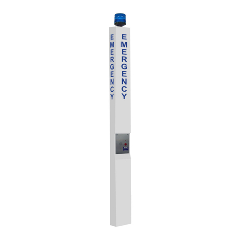
Other manuals for CB 1 Series
2
This manual suits for next models
6
Table of contents
Other Code Blue Emergency Phone manuals
Popular Emergency Phone manuals by other brands

Assistive Technology Services
Assistive Technology Services Help Dialer 700 troubleshooting guide

RATH MICROTECH
RATH MICROTECH SMARTPHONE IV Simplified Programming Instructions

TWIG
TWIG Bracer Getting started guide

Viking
Viking E-1600-02A supplementary guide

Memco
Memco C100 BASE1 installation guide

Memco
Memco C100 Base 4 installation guide