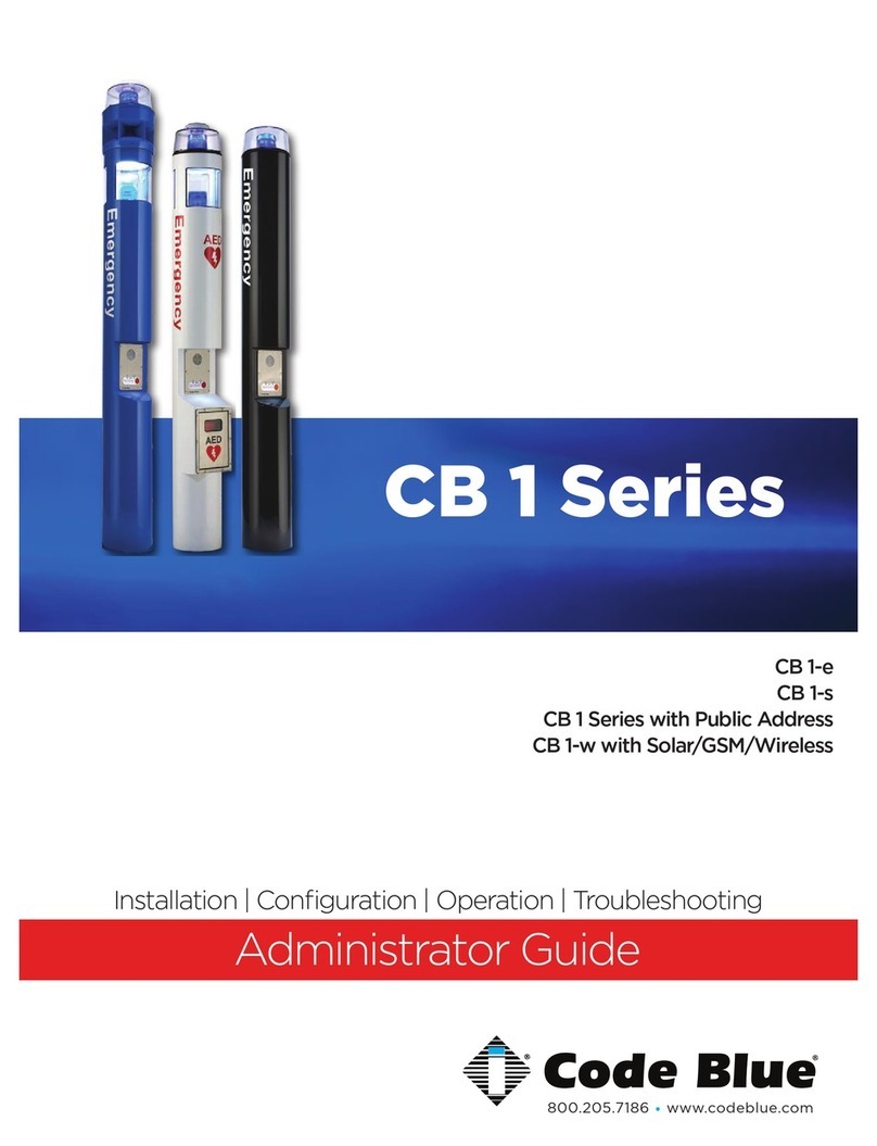
Code Blue CB 4 Series Manual

800.205.7186 • www.codeblue.com
CB4 Series
Model: ENBS02, ENBS03, ENBS04, & ENBS05
Admin Guide
Installation | Configuration | Support | Maintenance | Use

page 2 of 37
CB 4 Series
Administrator Guide
WARNING
ONLY QUALIFIED PERSONNEL SHOULD INSTALL THESE UNITS. THE INSTALLATION
SHOULD CONFORM TO ALL LOCAL CODES. IN SOME COUNTRIES, A CERTIFIED
ELECTRICIAN MAY BE REQUIRED.
NOTICE TO USERS
Copyright © Code Blue Corporation. All rights reserved. This guide or software
described herein, in whole or part, shall not be reproduced, translated or reduced to any
machine-readable form without prior written approval from Code Blue Corporation.
CODE BLUE CORPORATION PROVIDES NO WARRANTY WITH REGARD TO THIS
GUIDE, THE SOFTWARE OR OTHER INFORMATION CONTAINED HEREIN AND HEREBY
EXPRESSLY DISCLAIMS ANY IMPLIED WARRANTIES OF MERCHANTABILITY OR
FITNESS FOR ANY PARTICULAR PURPOSE WITH REGARD TO THIS GUIDE, THE
SOFTWARE OR SUCH OTHER INFORMATION. IN NO EVENT SHALL CODE BLUE
CORPORATION BE LIABLE FOR ANY INCIDENTAL, CONSEQUENTIAL, OR SPECIAL
DAMAGES, WHETHER BASED ON TORT, CONTRACT, OR OTHERWISE, ARISING OUT
OF OR IN CONNECTIONS WITH THIS GUIDE, THE SOFTWARE OR OTHER
INFORMATION CONTAINED HEREIN OR THE USE THEREOF.
Code Blue Corporation reserves the right to make any modifications to this guide or the
information contained herein at any time without notice. The software described herein
may also be governed by the terms of a separate user license agreement.
Code Blue® is a registered trademark of Code Blue Corporation. The names of actual
companies and products mentioned herein may be the trademarks of their respective
owners.
Code Blue • 259 Hedcor Street • Holland, MI 49423 USA • 800.205.7186 • www.codeblue.com GU-160-W

page 3 of 37
CB 4 Series
Administrator Guide
Table of Contents
Section
Section Title
Page #
2
Introduction
4
CB4 Model Photos
5
3
Safety Information
6
4
Installation Instructions
7
Getting Started
7
Tools Required
8
CB 4-s Installation Instructions
9
CB 4-s with Dual Faceplates Installation Instructions
11
CB 4-r Installation Instructions
13
CB 4-u Installation Instructions
15
5
Mounting Installation Instructions
18
CB 4 Series Pole Mount Installation Instructions
18
CB 4 Series Curb Mount Installation
19
6
Wiring Diagrams
21
6
Power Requirements
17
7
Wiring Diagram
21
100-240 AC / DC or 24V AC @ 60 Watt or 24V DC
21
PoE DIN Rail Power System | 48V DC 12.96w or 25.5w (CB 4-u
Only)
22
NightCharge® 120-240V AC @ 3 Amps NO Area Light | 12VDC 10
Amps (CB 4-u Only)
23
PoE - Non-DIN Rail Power System 480V DC 30 Watts PSE |
12.96w or 25.5w PD (CB 4-r & CB 4-s Only)
24
Multi-Tap Transformer (Power Brick) 110-347VAC (CB 4-u Only)
25
S-1000 & S-1050 Beacon/Strobe Operation
26
7
Power Requirements
28
8
Locating Unit Serial Numbers
32
9
Maintenance Schedule
33
10
Warranty
35
11
Download Information
36
12
Legal & Regulatory Information
37
Code Blue • 259 Hedcor Street • Holland, MI 49423 USA • 800.205.7186 • www.codeblue.com GU-160-W

page 4 of 37
2 Introduction
Thank you for choosing the CB 4 Series for your Code Blue application.
The CB 4 Series is our basic communication unit designed for wall or pole installations in
interior and exterior applications. The all-steel housing and Code Blue’s speakerphone
system meet the need for a highly vandal resistant unit, while providing a cost-effective
and reliable solution.
The CB 4 Series is a good choice for dorm and building entrances, hallways and transit
centers. The exclusive analog InterAct and VoIP speakerphones are designed for maximum
reliability, vandal resistance, auxiliary functions, mass notification control, and fault
monitoring and reporting capabilities. (see IA4100 or LS1000 guides for more information
on our speakerphones)
Our unmistakable craftsmanship makes our enclosures the most rugged on the market,
withstanding the punishment of natural and man-made disasters. CB 4 Series units have a
rugged steel construction, industrial engineering grade reflective graphics and weather, UV
and graffiti resistant paint.
Other options include:
• IP and analog phones
• Low power consumption LED faceplate light
• 180° Audio Paging Speaker
• Remote Mount Beacon/Strobe
• Cellular Communication – CB 4-u only
• NightCharge® – CB 4-u only
• Directory Plate
• Color IP Camera – CB 4-s with Dual Faceplates only
• Custom Cut-out Stainless Steel Plate – CB 4-u only
CB 4 Series
Administrator Guide
Code Blue • 259 Hedcor Street • Holland, MI 49423 USA • 800.205.7186 • www.codeblue.com GU-160-W

page 5 of 37
This guide contains all of the Code Blue CB 4 Series information for the CB 4-s, CB 4-u,
and CB 4-r. This guide contains a general overview of the CB 4 Series options and its
application, installation and wiring.
CB 4-s CB 4-r CB 4-s with
Dual Faceplates
CB 4-u
CB 4 Series
Administrator Guide
Code Blue • 259 Hedcor Street • Holland, MI 49423 USA • 800.205.7186 • www.codeblue.com GU-160-W

Code Blue • 259 Hedcor Street • Holland, MI 49423 USA • 800.205.7186 • www.codeblue.com page 6 of 37
CB 4 Series
Administrator Guide
Indicates a hazardous situation which, if not avoided, will result in
death or serious injury.
Indicates a hazardous situation which, if not avoided, could result in
death or serious injury.
CAUTION
Indicates a hazardous situation which, if not avoided, could result in
minor or moderate injury.
NOTICE
Indicates a situation which, if not avoided, could result in damage to
property.
IMPORTANT
Indicates significant information that is essential for proper product
functionality.
NOTE
Indicates useful information that helps get the most out of a
product.
3 Safety Information
HAZARD LEVELS LEGEND
WARNING
DANGER
Safety Instructions
Code Blue products shall be installed by trained professionals. The installation should
conform to all local codes. In some countries, a certified electrician may be required.
When transporting a Code Blue product, use the original packaging or equivalent to
prevent damage to the product.
Code Blue products shall be used in compliance with local laws and regulations.
Store the Code Blue product in a dry and ventilated environment.
Do not install the product on unstable brackets, surfaces or walls.
Use only applicable tools when installing Code Blue products.
Do not use chemicals, caustic agents, steel wool or aerosol cleaners other than those
tested and recommended by Code Blue.
Use only accessories that comply with technical specifications of the product. These
can be provided by Code Blue or a third party.
Use only spare/replacement parts provided by or recommended by Code Blue.
Transportation
When transporting a Code Blue product, use the original packaging or equivalent to
prevent damage to the product.
WARNING
NOTICE
NOTICE
GU-160-W

page 7 of 37
CB 4 Series
Administrator Guide
Important Notes:
Getting Started
EIA/TIA, ANSI, CSA and BICSI cabling or similar standards shall be adhered to
for proper operation of Code Blue communication devices connected to
copper or fiber infrastructures communications cable and electrical cable in
the same conduit is not an acceptable installation and shall not be supported.
Analog phones require a minimum of 23mA for proper operation (26-29mA
recommended).
Each analog speakerphone requires its own phone line or PBX extension.
Multiple units shall not be supported.
Speakerphones require programming before operation. Consult the
speakerphone’s Administrator Guide for instructions.
If you are installing IP speakerphones, please read the appropriate manuals
and consult with your Network Administrator.
Size electrical wiring based on length of run.
4 Installation Instructions
Code Blue • 259 Hedcor Street • Holland, MI 49423 USA • 800.205.7186 • www.codeblue.com GU-160-W

page 8 of 37
CB 4 Series
Administrator Guide
Tools Needed
Ladder to reach above unit - For Remote Beacon/Strobe Only
Drill & Security Bit for removing & inserting security screws on phone.
3/8” Socket set & extension to mount unit onto wall
Banding Tool if using Pole Mount kit
Drill & Security Bit for removing & inserting security screws on phone &
access plate.
3/8” Socket set & extension to mount unit onto wall
Banding Tool if using Pole Mount kit
CB 4-s & CB 4-r Units:
CB 4-u Units:
Code Blue • 259 Hedcor Street • Holland, MI 49423 USA • 800.205.7186 • www.codeblue.com GU-160-W

PRE-INSTALLATION
Electrical preparation – The unit may have supply wires run from either A) behind
the unit through the wall, or B) below the unit using an external conduit through
the bottom of the unit’s back plate. Holes in the back and bottom of the unit have
been provided for this purpose.
INSTALLATION PROCEDURES
Mark the mounting holes – In order to comply with the Americans with Disabilities
Act (ADA) of 1990, the speakerphone button(s) should be positioned between 34
and 48 inches from grade level. (Consult an ADA specialist in your area to verify
local and federal guidelines.)
Drill all marked holes.
Secure the housing to the wall – Four anchors of appropriate size and type should
be used to securely fasten the housing to the wall or pole mount.
Connect electrical and communications wiring. Follow all federal and local codes
that apply.
CONNECT THE POWER WIRING
Wiring
Grounding - One input power connector has been provided for power source
termination
Low Voltage - 12-24V AC or DC source voltage, choice is limited to the most
restricted voltage and type of voltage (ac or dc) required for the configuration
selected. See label with voltage and type inside the enclosure.
Maximum wattage - 12.96 watts
Pin 1 = Hot or Positive
Pin 2 = Neutral or Negative
Pin 3 = Ground
PoE Power Option
PoE cable must be terminated using a RJ-45 configured EIA/TIA T568b
configuration
Grounding - Depending on the facilities PoE deployment, grounding may be
terminated in the enclosure, or at the PoE source.
Connect the Phone Line (if required) - See phone installation instructions
Apply Power - The enclosure should become operational immediately after the
PoE Ethernet cable has been connected.
CB 4-s Installation Instructions
IMPORTANT: If wiring is coming in from the back, ensure that the conduit is aligned at
this time.
WARNING PoE is considered HIGH VOLTAGE (NEC) (range is 37-57v DC)
CAUTION - When PoE is grounded back at the switch/injector, use a shielded PoE
surge protector to eliminate ground loop potential, which can create data signal
corruption issues, as well as create a safety issue for users.
page 9 of 37
CB 4 Series
Administrator Guide
Code Blue • 259 Hedcor Street • Holland, MI 49423 USA • 800.205.7186 • www.codeblue.com
See diagrams next page
GU-160-W

page 10 of 37
BOTTOM
13 5/16 REF
4 9/16 REF
BOTTOM PLATE
Ø7/8
(KNOCKOUT FOR
Ø1/2 CONDUIT)
5 3/4
10 1/4 REF
2 7/8
5 1/8 REF
1 3/16
2 1/2 REF
2 1/4 REF
2 7/8
4 1/16
8
41-5/8
MOUNTING SURFACE
4 X Ø7/16 MOUNTING HOLES
Ø7/8 THRU BOTTOM PLATE
(KNOCKOUT FOR Ø1/2 CONDUIT)
GROUND/FLOOR
For dual button faceplate, deduct 3.25 inches.
For keypad faceplate, deduct 4.5 inches.
For wheelchair direct facing access only, deduct 6 inches.
Suggested installation dimensions shown from ground to lower right mounting hole are for
single button faceplates.
DISCLAIMER: The dimensions above are intended as guidelines only. For specific
installation requirements, reference your local codes.
All wiring must be installed and connected by experienced and certified personnel to meet local and
national electrical codes, and will include a service disconnect.
CB 4 Series
Administrator Guide
Code Blue • 259 Hedcor Street • Holland, MI 49423 USA • 800.205.7186 • www.codeblue.com GU-160-W

page 11 of 37
See diagrams next page
CB 4 Series
Administrator Guide
Code Blue • 259 Hedcor Street • Holland, MI 49423 USA • 800.205.7186 • www.codeblue.com
PRE-INSTALLATION
Electrical preparation – The unit may have supply wires run from either A) behind
the unit through the wall, or B) below the unit using an external conduit through the
bottom of the unit’s back plate. Holes in the back and bottom of the unit have been
provided for this purpose.
INSTALLATION PROCEDURES
Mark the mounting holes – In order to comply with the Americans with Disabilities
Act (ADA) of 1990, the speakerphone button(s) should be positioned between 34
and 48 inches from grade level. (Consult an ADA specialist in your area to verify
local and federal guidelines.)
Drill all marked holes.
Secure the housing to the wall – Four anchors of appropriate size and type should
be used to securely fasten the housing to the wall or pole mount.
Connect electrical and communications wiring. Follow all federal and local codes
that apply.
CONNECT THE POWER WIRING
Wiring
Grounding - One input power connector has been provided for power source
termination
Low Voltage 12-24V AC or DC source voltage, choice is limited to the most
restricted voltage and type of voltage (ac or dc) required for the configuration
selected. See label with voltage and type inside the enclosure.
Maximum wattage - 12.96 watts
Pin 1 = Hot or Positive
Pin 2 = Neutral or Negative
Pin 3 = Ground
PoE Power Option
PoE cable must be terminated using a RJ-45 configured EIA/TIA T568b
configuration
Gounding - Depending on the facilities PoE deployment, grounding may be
terminated in the enclosure, or at the PoE source.
Connect the Phone Line (if required) - See phone installation instructions
Apply Power - The enclosure should become operational immediately after the PoE
Ethernet cable has been connected.
IMPORTANT: If wiring is coming in from the back, ensure that the conduit is aligned at this
time.
WARNING PoE is considered HIGH VOLTAGE (NEC) (range is 37-57v DC)
CAUTION - When PoE is grounded back at the switch/injector, use a shielded PoE
surge protector to eliminate ground loop potential, which can create data signal
corruption issues, as well as create a safety issue for users.
CB 4-s with Dual Faceplates Installation Instructions
GU-160-W

page 12 of 37
BOTTOM
25 3/4 REF
4 9/16 REF
BOTTOM PLATE
Ø7/8
(KNOCKOUT FOR
Ø1/2 CONDUIT)
5 3/4
10 1/4 REF
2 7/8
5 1/8 REF
1 3/16
8 3/4 REF
2 1/4 REF
4 1/16
8
47-7/8
MOUNTING SURFACE
4 X Ø7/16 MOUNTING HOLES
Ø7/8 THRU BOTTOM PLATE
(KNOCKOUT FOR Ø1/2 CONDUIT)
GROUND/FLOOR
All wiring must be installed and connected by experienced and certified personnel to meet local
and national electrical codes, and will include a service disconnect.
For dual button faceplate, deduct 3.25 inches.
For keypad faceplate, deduct 4.5 inches.
For wheelchair direct facing access only, deduct 6 inches.
Suggested installation dimensions shown from ground to lower right mounting hole are for
single button faceplates.
DISCLAIMER: The dimensions above are intended as guidelines only. For specific
installation requirements, reference your local codes.
CB 4 Series
Administrator Guide
Code Blue • 259 Hedcor Street • Holland, MI 49423 USA • 800.205.7186 • www.codeblue.com GU-160-W

G R A P H I C
PRE-INSTALLATION
Electrical preparation – The unit may have supply wires run from either A)
behind the unit through the wall, or B) below the unit using an external conduit
through the bottom of the unit. Holes in the back and bottom of the unit have
been provided for this purpose.
INSTALLATION PROCEDURES
Mark the mounting holes – In order to comply with the Americans with
Disabilities Act (ADA)of 1990, the speakerphone button(s) should 15-1/4 be
positioned between 34 and 48 inches from grade level (Consult an ADA
specialist in your area to verify local and federal guidelines).
Drill all marked holes.
Secure the housing to the wall – Four anchors of appropriate size and type
should be used to securely fasten the housing to the wall or pole mount.
Connect electrical and communications wiring. Follow all federal and local
codes that apply.
CONNECT THE POWER WIRING
Wiring
Grounding - One input power connector has been provided for power source
termination
Low Voltage 12-24V AC or DC source voltage, choice is limited to the most
restricted voltage and type of voltage (ac or dc) required for the configuration
selected. See label with voltage and type inside the enclosure.
Maximum wattage - 12.96 watts
Pin 1 = Hot or Positive
Pin 2 = Neutral or Negative
Pin 3 = Ground
PoE Power Option
PoE cable must be terminated using a RJ-45 configured EIA/TIA T568b
configuration
Grounding - Depending on the facilities PoE deployment, grounding may be
terminated in the enclosure, or at the PoE source.
Connect the Phone Line (if required) - See phone installation instructions
Apply Power - The enclosure should become operational immediately after the
PoE Ethernet cable has been connected.
IMPORTANT: If wiring is coming in from the back, ensure that the conduit is aligned at
this time.
WARNING PoE is considered HIGH VOLTAGE (NEC) (range is 37-57v DC)
CAUTION - When PoE is grounded back at the switch/injector, use a shielded PoE
surge protector to eliminate ground loop potential, which can create data signal
corruption issues, as well as create a safety issue for users.
page 13 of 37
CB 4 Series
Administrator Guide
Code Blue • 259 Hedcor Street • Holland, MI 49423 USA • 800.205.7186 • www.codeblue.com
CB 4-r Installation Instructions
GU-160-W

page 14 of 37
BOTTOM
15 1/4 REF
4 9/16 REF
BOTTOM PLATE
Ø7/8
(KNOCKOUT FOR
Ø1/2 CONDUIT)
5 3/4
10 1/4 REF
2 7/8
5 1/8 REF
1 3/16
2 3/4 REF
2 1/4 REF
2 7/8
4 1/16
8
41-5/8
MOUNTING SURFACE
4 X Ø7/16 MOUNTING HOLES
Ø7/8 THRU BOTTOM PLATE
(KNOCKOUT FOR Ø1/2 CONDUIT)
GROUND/FLOOR
For dual button faceplate, deduct 3.25 inches.
For keypad faceplate, deduct 4.5 inches.
For wheelchair direct facing access only, deduct 6 inches.
Suggested installation dimensions shown from ground to lower right mounting hole are for
single button faceplates.
DISCLAIMER: The dimensions above are intended as guidelines only. For specific
installation requirements, reference your local codes.
All wiring must be installed and connected by experienced and certified personnel to meet local and national
electrical codes, and will include a service disconnect.
CB 4 Series
Administrator Guide
Code Blue • 259 Hedcor Street • Holland, MI 49423 USA • 800.205.7186 • www.codeblue.com GU-160-W

page 15 of 37
CB 4-u Installation Instructions
CB 4 Series
Administrator Guide
Code Blue • 259 Hedcor Street • Holland, MI 49423 USA • 800.205.7186 • www.codeblue.com
PRE-INSTALLATION
Electrical preparation – The unit may have supply wires run from either (a) behind the
unit through the wall, or (b) below the unit using an external conduit through the bottom
of the unit’s back plate. Holes in the bottom of the unit have been provided for this
purpose. Holes in the back of the unit must be provided by others.
INSTALLATION PROCEDURES
Mark the mounting holes – In order to comply with the Americans with Disabilities Act
(ADA) of 1990, the speakerphone button(s) should be positioned between 34 and 48
inches from grade level. (Consult an ADA specialist in your area to verify local and federal
guidelines.)
Drill all marked holes.
Secure the housing to the wall – Four anchors of appropriate size and type should be
used to securely fasten the housing to the wall or pole mount.
Connect electrical and communications wiring (see wiring instructions). Follow all
national and local codes that apply.
CONNECT THE POWER WIRING
Wiring
Grounding - One input power connector has been provided for power source
termination
Low Voltage 12-24V AC or DC source voltage, choice is limited to the most restricted
voltage and type of voltage (ac or dc) required for the configuration selected. See
label with voltage and type inside the enclosure.
Maximum wattage - 12.96 watts
Pin 1 = Hot or Positive
Pin 2 = Neutral or Negative
Pin 3 = Ground
PoE Power Option (range is 37-57v DC)
PoE cable must be terminated using a RJ-45 configured EIA/TIA T568b configuration
Grounding - Depending on the facilities PoE deployment, grounding may be
terminated in the enclosure, or at the PoE source.
NightCharge Option (voltage range 110 – 220 Max wattage of 600w)
See diagram and instructions on page 25
Power Brick Option (voltage range 110 - 347 210 watts)
See diagram and instructions on page 27
Connect the Phone Line (if required) - See phone installation instructions
Apply Power - The enclosure should become operational immediately after the PoE
Ethernet cable has been connected.
IMPORTANT: If wiring is being supplied from the back, ensure that the conduit is aligned at this
time.
CAUTION - When PoE is grounded back at the switch/injector, use a shielded PoE surge
protector to eliminate ground loop potential, which can create data signal corruption issues, as
well as create a safety issue for users.
GU-160-W

page 16 of 37
CB 4 Series
Administrator Guide
Code Blue • 259 Hedcor Street • Holland, MI 49423 USA • 800.205.7186 • www.codeblue.com GU-160-W

page 17 of 37
All wiring must be installed and connected by experienced and certified personnel to meet local and national
electrical codes, and will include a service disconnect.
BOTTOM
25 3/4 REF
Ø1-1/8 THRU TOP PLATE
(KNOCKOUT FOR Ø3/4 CONDUIT)
8 7/8 REF
BOTTOM PLATE
2 7/8
5 3/4
14 REF
1 5/8 REF
2 1/2
8
1 5/8
9 1/8 REF
4 1/8 REF
40-1/4
MOUNTING SURFACE
4 X Ø9/16 MOUNTING HOLES
Ø1-1/8 THRU BOTTOM PLATE
(KNOCKOUT FOR 3/4 CONDUIT)
GROUND/FLOOR
CB 4 Series
Administrator Guide
Code Blue • 259 Hedcor Street • Holland, MI 49423 USA • 800.205.7186 • www.codeblue.com GU-160-W

page 18 of
37
5 Mounting Installation Instructions
CB 4 Series Pole Mount Installation Instructions
Banding tool sold separately.
See Parts Order Form, part #41441.
CB 4 Series
Administrator Guide
Code Blue • 259 Hedcor Street • Holland, MI 49423 USA • 800.205.7186 • www.codeblue.com
THREAD MOUNTING STRAPS THROUGH SLOTS
Use outside slots for larger poles and inside slots for smaller poles.
HOLD BRACKET TO POLE
Set the height of the bracket (C) so that the speakerphone push button(s)
on the unit will be at desired height (please check with local codes for ADA
compliance).
BAND THE BRACKET TO THE POLE AT DESIRED HEIGHT
To eliminate waste, pull band (A) from carton as needed. With ears of
buckle (B) away from operator, slide the buckle on the banding. Lace
banding around the object being clamped and again through buckle.
Bend end of band under buckle.
Slide band in tool nose slot. Press down on gripper with thumb and tension
clamp by turning the handle. Maximum tension has been reached when the
band stops moving through the buckle.
When maximum tension has been reached, roll tool over buckle, at same
time reversing handle carefully at approximately three-quarters turn to
avoid breakage. The band that is released will be used in the bend and
therefore there is no loss of tension.
Lift cutter lever and the band will be cut to correct length. While holding
the stub of the band with your thumb, hammer flat over bridge of buckle.
Complete application by hammering the buckle ears over the stub.
ATTACH ENCLOSURE TO BRACKET
Place a rubber washer (D) on each of the four studs.
Align and place the back plate of the unit over the four studs.
Place a second set of rubber washers on each of the four studs (inside the
unit).
Place a steel washer (E) on each of the four studs.
Turn a nut (F) on each of the four studs.
GU-160-W

page 19 of 37
CB 4 Series Curb Mount Installation
CB 4 Series
Administrator Guide
Code Blue • 259 Hedcor Street • Holland, MI 49423 USA • 800.205.7186 • www.codeblue.com
PRE-INSTALLATION – Use outside slots for larger poles and inside slots for
smaller poles.
Electrical Preparation – The unit will need phone and electrical wires
running through the curb mount with at least 16 inches of wire coming out
of the top of the curb mount to connect to the Code Blue phone. A 7/8 inch
conduit hole in the back of the unit has been provided.
INSTALLATION PROCEDURES – Curb Mounts should be mounted on concrete
bases with a minimum depth of 4 inches, using the correct mounting bolts for
your application.
Mounting Holes – In order to comply with the Americans with Disabilities
Act (ADA) of 1990, the speakerphone button(s) should be positioned
between 34 and 48 inches from grade level (consult an ADA specialist in
your area to verify local and federal guidelines).
Secure the housing to the Curb Mount – Four bolts with 4 lock nuts, 4
rubber washers and 8 steel washers are provided to securely fasten the
housing to the curb mount. Connect electrical and communications wiring.
Follow all federal and local codes that apply.
See curb mount diagrams on next page
GU-160-W

page 20 of 37
CB 4 Series
Administrator Guide
Code Blue • 259 Hedcor Street • Holland, MI 49423 USA • 800.205.7186 • www.codeblue.com GU-160-W
Other manuals for CB 4 Series
1
This manual suits for next models
7
Table of contents
Other Code Blue Emergency Phone manuals
Popular Emergency Phone manuals by other brands

Tunstall
Tunstall Caresse Installation and user guide

EmerCom Technologies
EmerCom Technologies EMC-60 user guide

GAI-Tronics
GAI-Tronics PHP400 Design installation and user guide

Viking
Viking E-1600A-BLT-EWP product manual

Hubbell
Hubbell Gai-Tronics Red Alert 300 Series manual

Talkaphone
Talkaphone AOR-8 installation guide