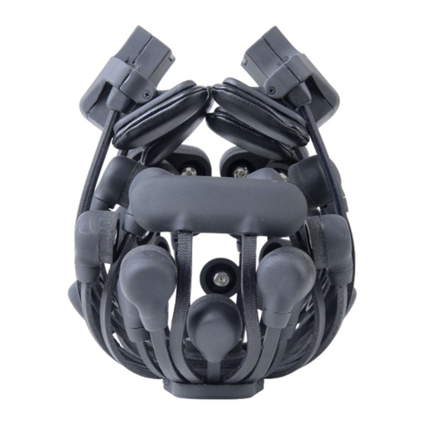
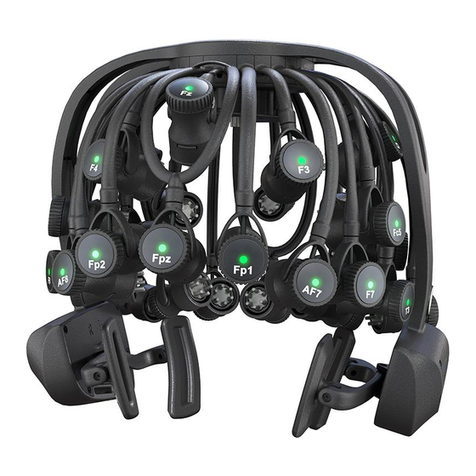
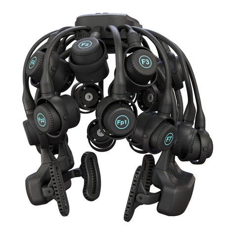
Cognionics Quick-20 User manual

QUICK-20 DRY EEG HEADSET
USER GUIDE
Cognionics, Inc.
8445 Camino Santa Fe
Suite 205
San Diego, CA 92121
!"#$%"$%&'

Cont ent s
1AbouttheManual 3
2StandardPackageContents 5
3AbouttheQuick-20 9
3.1 Part s of t he Headset . . . . . . . . . . . . . . . . . . . . . . . 9
3.2 SensorLayout .......................... 13
3.3 Specifications .......................... 14
4CareandHandling 15
5PreparingtheHeadset 17
5.1 Insert ing t he Bat t ery . . . . . . . . . . . . . . . . . . . . . . . 17
5.2 Inst alling t he Sensors . . . . . . . . . . . . . . . . . . . . . . . 19
5.3 St art ing t he Acquisit ion Soft ware . . . . . . . . . . . . . . . . 20
6ApplyingtheHeadsetandOptimizingSensorContact 23
6.1 Placing t he Headset . . . . . . . . . . . . . . . . . . . . . . . 23
6.2 Opt imizing Sensor Cont act . . . . . . . . . . . . . . . . . . . 28
1

Cont ent s
7Recording 33
7.1 Using t he Cognionics Dat a Acquisit ion Soft ware . . . . . . . . 33
7.2 UsingtheSDCard........................ 33
8Removal,CleaningandStorage 35
8.1 Removing t he Headset . . . . . . . . . . . . . . . . . . . . . . 35
8.2 Cleaning t he Headset . . . . . . . . . . . . . . . . . . . . . . 35
8.3 Removing and Cleaning t he Sensors . . . . . . . . . . . . . . . 36
8.4 Storage.............................. 37
9Troubleshooting 39
9.1 Reset t ing t he Amplifier . . . . . . . . . . . . . . . . . . . . . 39
9.2 Power .............................. 39
9.3 Connectivity ........................... 39
9.4 SignalQuality .......................... 40
2

CHAPT ER 1
About the Manual
Congrat ulat i ons on t he purchase of your new Cogni oni cs Quick-20 Dry EEG
Headset . This manual is organized as a detailed step-by-step guide on set ting up
and using t he device. Please read t hrough t he ent ire manual first t o familiarize
yourself wit h t he operat ion of your headset before proceeding wit h your first
recording.
Note: The Quick-20 is for invest igat ional use only. It is not a FDA-approved
medical device.
3


CHAPT ER 2
St andar d Package Cont ent s
Your Quick-20 kit includes all of the necessary components for conducting dry
EEG recordings:
1. Quick-20 Headset
-ThedryEEGheadsetcontainingtheamplifierand
wireless t ransmit t er.
2. Bluetooth Dongle
-EachQuick-20ispairedtoadedicatedhigh-
reliability, high-speed reciever dongle which plugs into your computer’s
USB port .
3. Flex Sensor -flexibledryelectrodeforuseoverhair.
4. Drypad Sensor
-Flatdryelectrodeforuseoverareaswithlightorno
hair.
5. Ear Clip W ire
-Theearclipwiresareusedtoplacedrypadsensorson
to the earlobes.
6. Battery
-TheQuick-20acceptsCanonNB-9L3.7voltlithium-ionbat-
teries.
7. Battery Charger -Wallchargerforthebattery.
8. microSD card and adapter
-ThekitcomeswithamicroSDHC8GB
card for o!ine recordings.
5

2. St andar d Pack age Cont ent s
9. Electric Cleaning Brush
-MotorizedbrushforcleaningtheQuick-20
Headset .
10. Hand Sanitizer -Fluidforusewiththecleaningbrush.
Depending on your specific configuration, you may have also received ad-
dit ional component s such as our Wireless Trigger or Auxiliary Input Module.
Please refer t o t heir specific manuals for det ailed inst ruct ions.
Please verify t hat you have received all t he it ems list ed on your purchase
order. Cont act us immediat ely if you are missing any component s.
6

Quick- 20 Headset
Bl ue t oo t h
Dongle
Pur e ll Ha nd San it iz er
Dryp ad Sensors
Recha r geab le Li-ion
Ba t t er i e s w it h Ch a r g er
Ear Cl i p Wir e
Flex Sensors
Ele ct r ic Br u sh
microSD card
with Ad apter
Standard Quick-20 Kit Components
7


CHAPT ER 3
About the Quick-20
3.1 Part s of t he Headset
The Cognionics Quick-20 integrates the EEG amplifier and wireless transmitter
into an easy-to-use, self-contained headset. The main components include:
1. Power Button
-Pushbuttontoturntheheadsetonando".Thepower
but t on is also used as a reset swit ch t o bring t he amplifier’s set t ings t o
their default values. To reset the device, turn the headset o".Thenpress
and hold t he power but t on unt il t he main power LED flashes blue.
2. Battery Compartment
-TheQuick-20containstwobatterycompart-
ment s. T he Lit hium-ion rechargeable bat t eries can be hot swapped during
use.
3. Power LED
-Indicatorofpowerandbatterystatus. Seepicturefor
descript ion of LED color codes.
4. Trigger LED
-Indicatoroftriggerlinkstatus. Seepicturefordescription
of LED color codes.
5. flexible Leg
-TheQuick-20usesanarrayofflexiblelegstoconformto
di"er ent head si zes and shapes.
6. Sensor Pod
-Eachsensorpodiscapableofswivelingtomatchthe
cont ours of t he head. T he pod also houses an act ive amplifier t o bu"er
9

3. A bout t he Quick -20
the EEG signal and a conductive outer layer, forming a faraday cage, to
shi el d t he el ect r ode f r om ext er nal el ect r i cal i nt er f er ence.
7. Sensor Connect or
-Sensorsareattachedviaaminiaturesnapconnector.
8. Accessory Connector
-TheQuick-20hasaportforattachinganAuxil-
iary Input Module for external sensors. The port can also be used with
the wired data dongle.
Do not connect the Quick-20 to a standard USB port.
9. microSD Card Slot
-TheQuick-20acceptsmicroSDcardsforrecording
to flash memory.
10. Ear Band -flexiblebandsupportingtheearpads.
11. Ear Pad -Cushionedpadtocuparoundthesubject’sear.
12. Ear Clip Connector
-Jackforattachingthetwoearclipwiresforthe
A1 and A2 positions.
10

3.1. Parts of the Headset
Po w er B u t t o n
Po w e r L ED
Green –On
+Red Bl i n k –20%battery life
+Red –10%battery life
microSD Slot
Connector f or
t he A ux iliary Input Mo du le
or Wired Data Dongle
Trigger Status LED
+BlueDi m –Trigger in range
+Bl u e Fl ash – New m ark er recei ved
11

3. A bout t he Quick -20
Pow er But t o n
Bat t ery Cover
Fl e x i b l e Le g
Sensor Pod
Sensor Connect or
Ea r Pa d
Ear Cli p Connect or
12

3.2. Sensor Layout
3.2 Sensor Layout
The Quick-20 follows the international 10-20 layout with a total of 23 electrode
positions (20-channels plus reference plus 2 grounds). The common reference
is located at A1 via the ear clip. Two grounds, for redundancy, are located
adj acent t o t he Fp1 and Fp2 posit ions. Not e: some headset s have cust om
layouts. If so, refer to your order for specifics.
Always ensure that reference and ground are physically touching the skin.
The impedance check and all of the channels rely on the reference and ground
el ect r odes havi ng cont act wi t h t he subj ect ’s ski n.
O1O2
P7
P3PzP4
P8
T4 C4 Cz C3 T3
F7
F3FzF4
F8
Gnd Fp 2 Fp 1 Gn d
A2
A1/
Ref
Standard full Quick-20 sensor placement. The Quick-20 approximates the
st andar d 10- 20 l ayout acr oss most head si zes.
13

3. A bout t he Quick -20
3.3 Specificat ions
Channel Count 20 plus reference and ground
Sensor Type Active electrodes with active shielding
Analog-to-digital Conversion 24-bit simult aneous sampling
Sampl i ng Rat e 500 and 1,000 samples/ sec
Impedance Monitoring Real-t ime wit h EEG acquisit ion
Noise 0.7 µV RMS from 1-50 Hz, shorted inputs
Wireless Cust om high-speed Bluet oot h
Power Lithium-ion, 8 hr wireless, 16 hr microSD
Triggering Cogni oni cs wi reless t rigger
Weight 450 g wit h bat t eries
Note: specificat ions subject to change depending on model revisions and
requested customizations.
14

CHAPT ER 4
Care and Handl i ng
The Quick-20 is designed to be a robust, durable headset suitable for use in
real-world environments. To keep your Quick-20 functioning optimally, take
not e of t he following it ems:
•Avoid excessively bending the legs or earband
-TheQuick-20relies
on t he flexibilit y of t he leg mat erial t o deflect and conform across t he
many variat ions in head shapes. Do not grab and deliberat ely bend t he
legs or ear bands beyond the range necessary to apply the system on a
subj ect .
•Never connect the Quick-20 to a standard USB port
-Themi-
croUSB port on t he Quick-20 is designed t o work only wit h Cognionics
accessories, which provide elect rical isolat ion t o prot ect t he headset and
subj ect f r om el ect r i cal shock. Di r ect l y connect i ng t he Qui ck -20 t o a
PC, wit hout t he special isolat ion dongle, will not work. Connect ing t he
Quick-20 t o a USB port will not recharge t he bat t eries. Misuse of t he
USB port may result in damage t o t he headset .
•Do not immerse the headset in a liquid
-Whencleaningthesystem
wit h isopropyl or sanit izer, use just enough liquid t o moist en t he brush.
Avoid dispensing liquid into the sensor pods or any other opening in the
headset t o prevent damage t o t he headset ’s elect ronics.
•Do not compress the legs of the headset
-Usethesuppliedcarrying
case t o st ore and ship t he Quick-20. Avoid placing t he Quick-20 in boxes
15

4. Car e and Handl ing
that apply pressure to the legs since long-term compression may cause
the headset to deform. If the legs of the headset become compressed, the
syst em may become t i ght and uncomf or t abl e f or t he subj ect .
•Do not pull on the ear clip wire
-Whenremovingtheearclipfrom
the headset, grasp the base of the connector, rather than the wire.
16

CHAPT ER 5
Preparing t he Headset
5.1 Insert ing t he Bat t ery
Make surethebatteries arefully charged. Place theprovided lithium-ion batteries
into the charger and wait until the charger indicates that the battery is full.
The Quick-20 features dual hot-swappable batteries on each earpad. The
device will funct ion wit h a bat t ery in eit her, or bot h, compart ment s. If bot h
bat t eries are insert ed, t he right hand side bat t ery will be used t o recharge t he
left side battery.
17

5. Pr epar ing t he Headset
a b
(a) Open the battery cover. (b) Insert one lithium-ion battery. Make sure
that the battery is inserted in the correct orientation. The metal contacts
on the battery should be oriented towards the top of the headset.
18

5.2. Installing the Sensors
5.2 Installing the Sensors
a b
Insert flex sensors for areas that are covered by hair. On most subjects, this
is all positions except for Fp1, Fp2, F7 and F8. (a) Grasp the sensor and
(b) push down on the center of the sensor into the receptacle. For areas
wit h light or no hair, insert drypad sensors.
When inserting sensors, always push at the center of the sensor. For flex
sensor s, do not appl y pr essur e or b end t he sensor t i ps t o avoi d damage. When
removing sensors, always pry between the sensor and the connector. Do not pull
on the tips of the flex sensors to avoid damage.
19
Other manuals for Quick-20
1
Table of contents
Other Cognionics Laboratory Equipment manuals
Popular Laboratory Equipment manuals by other brands

SynOptics
SynOptics SYNBIOSIS aCOLyte 3 HD quick guide

Christ
Christ Epsilon 2-10D LSCplus operating manual

cytiva
cytiva Amersham ERASER operating instructions

Thermo Scientific
Thermo Scientific Neslab EX-7 Installation, Operation, Basic Maintenance

Renfert
Renfert SILENT EC2 Faq

PerkinElmer
PerkinElmer Panthera-Puncher 9 user manual

MicroDigial
MicroDigial Nabi user manual

Keysight
Keysight E8257D Option H1K Installation notes

Cole Parmer
Cole Parmer TR-200 Series instruction manual

K-Systems
K-Systems AV1 user manual

Waters
Waters ACQUITY CM-30S Overview and maintenance guide

Zymo Research
Zymo Research ZymoPURE Plasmid Miniprep instruction manual