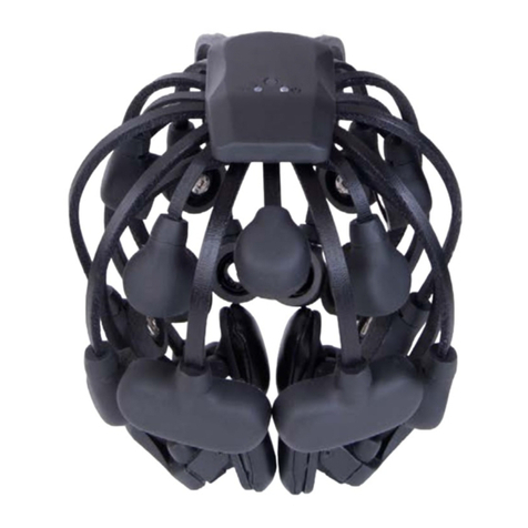
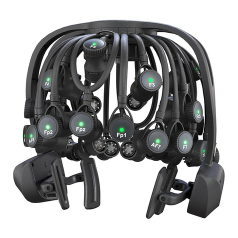
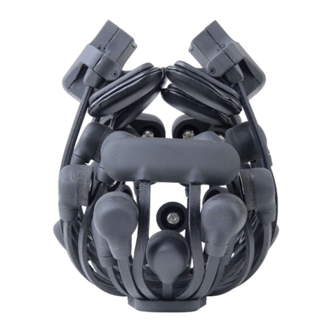
Cognionics Quick Series User manual

Contents
1 About the Manual 3
1.1 The Quick-20 and the Quick-30 ................. 3
2 Standard Package Contents 5
3 About the Quick Headsets 9
3.1 Parts of the Headset ....................... 9
3.2 Sensor Layout .......................... 13
3.3 Specifications .......................... 14
4 Preparing the Headset 17
4.1 Inserting the Battery ....................... 17
4.2 Installing the Sensors ....................... 19
4.3 Starting the Acquisition Software ................ 21
5 Applying the Headset 23
5.1 Placing the Headset ....................... 23
5.2 Optimizing Sensor Contact ................... 28
1

Contents
6 Beginning a Recording 33
6.1 Using the Cognionics Data Acquisition Software ........ 33
6.2 Using the microSD Card ..................... 33
7 Ending a Session 35
7.1 Removing the Headset ...................... 35
7.2 Storage .............................. 35
8 Care and Handling 37
9 Troubleshooting 39
9.1 Resetting the Amplifier ..................... 39
9.2 Power .............................. 39
9.3 Other Issues ........................... 39
2

CHAPTER 1
About the Manual
Congratulations on the purchase of your new Cognionics Quick Series Dry EEG
Headset. This manual is organized as a detailed step-by-step guide on setting up
and using the device. Please read through the entire manual first to familiarize
yourself with the operation of your headset before proceeding with your first
recording.
1.1 The Quick-20 and the Quick-30
This documentation is written for both the Quick-20 and the Quick-30, as they
share many characteristics. Both have the same fundamental 10/20 channel
layout, though the Quick-30 has 10 additional channels in addition to the
standard 10/20 channels. The Quick-20 contains two grounds in the outer
sensors of the two dual-pods in the front, while the Quick-30 contains one
ground, which is located in the center of the triple pod in the front. The
Quick-30 also has two dual pods in the back of the headset. Regardless of
which headset you’ve received, this documentation serves as a guide to help
you set up and use your headset. In addition, our wiki contains resources to
help you get started with your Quick-20 or Quick-30 headset. It is located at
http://www.cognionics.com/wiki/.
Note: The Quick-20 and Quick-30 are for investigational use only. They
are not FDA-approved medical devices.
3


CHAPTER 2
Standard Package Contents
Your Quick-20 or Quick-30 kit includes all of the necessary components for
conducting dry EEG recordings:
1. Quick-20/Quick-30 Headset
- The dry EEG headset containing the
amplifier and wireless transmitter.
2. Bluetooth Dongle
- Each Quick headset is paired to a dedicated high-
reliability, high-speed reciever dongle which plugs into your computer’s
USB port.
3. Flex Sensor - flexible dry electrode for use over hair.
4. Drypad Sensor
- Flat dry electrode for use over areas with light or no
hair.
5. Ear Clip Wire
- The ear clip wires are used to place drypad sensors on
to the earlobes.
6. Battery
- The Quick headsets accept Canon NB-9L 3.7 volt lithium-ion
batteries.
7. Battery Charger - Wall charger for the battery.
8. microSD card and adapter
- The kit comes with a microSDHC 8GB
card for o✏ine recordings.
5

2. Standard Package Contents
9. Electric Cleaning Brush
- Motorized brush for cleaning the Quick-20
and Quick-30 Headsets.
10. Hand Sanitizer - Fluid for use with the cleaning brush.
Depending on your specific configuration, your headset may look di↵erent
from that shown in the pictures below. You may have also received additional
components such as our Wireless Trigger or Auxiliary Input Module. Please
refer to their specific manuals for detailed instructions.
Please verify that you have received all the items listed on your purchase
order. Contact us immediately if you are missing any components.
6

Quick series Headset
Standard Quick Kit Components
7


CHAPTER 3
About the Quick Headsets
3.1 Parts of the Headset
The Cognionics Quick-20 and Quick-30 integrate the EEG amplifier and wireless
transmitter into an easy-to-use, self-contained headset. The main components
include:
1. Power Button
- Push button to turn the headset on and o↵.Thepower
button is also used as a reset switch to bring the amplifier’s settings to
their default values. To reset the device, turn the headset o↵. Then press
and hold the power button until the main power LED flashes blue.
2. Battery Compartment
- The Quick-20 and Quick-30 contain two battery
compartments. The Lithium-ion rechargeable batteries can be hot swapped
during use.
3. Power LED
- Indicator of power and battery status. See picture for
description of LED color codes.
4. Trigger LED
- Indicator of trigger link status. See picture for description
of LED color codes.
5. flexible Leg
- The headset uses an array of flexible legs to conform to
di↵erent head sizes and shapes.
9

3. About the Quick Headsets
6. Sensor Pod
- Each sensor pod is capable of swiveling to match the
contours of the head. The pod also houses an active amplifier to bu↵er
the EEG signal and a conductive outer layer, forming a faraday cage, to
shield the electrode from external electrical interference.
7. Sensor Connector
- Sensors are attached via a miniature snap connector.
8. Accessory Connector
- The Quick headsets have a port for attaching
an Auxiliary Input Module for external sensors. The port can also be used
with the wired data dongle.
Do not connect your headset to a standard USB port.
9. microSD Card Slot
- The Quick-20 and Quick-30 accept microSD cards
for recording to flash memory.
10. Ear Band - flexible band supporting the ear pads.
11. Ear Pad - Cushioned pad to cup around the subject’s ear.
12. Ear Clip Connector
- Jack for attaching the two ear clip wires for the
A1 and A2 positions.
10

3.1. Parts of the Headset
Power B utton
Power LED
Green –On
+Red Bli nk –20% battery life
+Red –10% battery life
microSD Slot
Connector for
the Auxiliary Input Module
or Wired Data Dongle
Trigger Status LED
+Blue Di m –Trigger in range
+Blu e Flash –New m ark er rec ei ved
11

3. About the Quick Headsets
Power Button
Battery Cover
Flexible Leg
Sensor Pod
Sensor Connector
Ear Pa d
Ear Clip Connector
12

3.2. Sensor Layout
3.2 Sensor Layout
The standard Quick-20 follows the international 10-20 layout with a total of 23
electrode positions (20-channels plus reference plus 2 grounds). The standard
Quick-30 incorporates all of these positions as well as 10 extra channels. The
common reference is located at A1 via the ear clip. On the Quick-20, Two
grounds for redundancy are located adjacent to the Fp1 and Fp2 positions. On
the Quick-30, the ground is between Fp1 and Fp2. Note: some headsets have
custom layouts. If so, refer to your order for specifics.
Always ensure that reference and ground are physically touching the skin.
The impedance check and all of the channels rely on the reference and ground
electrodes having contact with the subject’s skin.
13

3. About the Quick Headsets
Quick-20
Quick-30
Standard full Quick series sensor placement. The headsets are seen from
the front. The Quick headsets approximate the standard 10-20 layout
across most head sizes, though the Quick-30 has additional channels.
3.3 Specifications
14

3.3. Specifications
Headset Quick-20 and Quick-30
Channel Count 20, 30, or custom amount plus reference and ground
Sensor Type Active electrodes with active shielding
Analog-to-digital Conversion 24-bit simultaneous sampling
Sampling Rate 500 and 1,000 samples/sec
Impedance Monitoring Real-time with EEG acquisition
Noise 0.7 µVRMSfrom1-50Hz,shortedinputs
Wireless Custom high-speed Bluetooth
Power Lithium-ion, 8 hr wireless, 16 hr microSD
Triggering Cognionics wireless trigger (USB or Full)
Note: specifications subject to change depending on model revisions and
requested customizations.
15


CHAPTER 4
Preparing the Headset
4.1 Inserting the Battery
Make sure the batteries are fully charged. Place the provided lithium-ion batteries
into the charger and wait until the charger indicates that the battery is full.
Both the Quick-30 and Quick-20 feature dual hot-swappable batteries on each
earpad. The devices will function with a battery in either, or both, compartments.
If both batteries are inserted, the right hand side battery will be used to recharge
the left side battery.
17

4. Preparing the Headset
a b
(a) Open the battery cover. (b) Insert one lithium-ion battery. Make sure
that the battery is inserted in the correct orientation. The metal contacts
on the battery should be oriented towards the top of the headset.
18

4.2. Installing the Sensors
4.2 Installing the Sensors
a b
Flex sensors should be used on areas with hair. On most subjects, this is all
positions except for Fp1, Fp2, F7 and F8. Positions where the subject has
no hair should be equipped with drypad sensors. (a) Grasp the sensor and
(b) push down on the center of the sensor into the receptacle.
When inserting sensors, always push at the center of the sensor. For flex
sensors, do not apply pressure or bend the sensor tips to avoid damage. When
removing sensors, always pry between the sensor and the connector. Do not pull
on the tips of the flex sensors to avoid damage.
19

4. Preparing the Headset
a b
(a) Grab the two supplied ear clip wires. Pinch the ear clip to expose the
snap connector and (b) insert a drypad sensor, if one is not already
installed.
ba
(a) Grab the connector end of the ear clip wire. (b) Firmly insert the
connector into the jacks at the base of each ear band. You should feel a
’click’ when the connector is fully seated.
20
This manual suits for next models
2
Table of contents
Other Cognionics Laboratory Equipment manuals
Popular Laboratory Equipment manuals by other brands

Heraeus
Heraeus CRYOFUGE 6000i operating instructions

Reverberi
Reverberi SERENA Use and maintenance manual for the technician

Oxford Instruments
Oxford Instruments OpAL System manual

Campbell
Campbell SkyVUE 8M Quick Deploy Guide

Julabo
Julabo EH operating manual

cytiva
cytiva ReadyToProcess STF - Dry operating instructions

Univex
Univex DR11 Operator's manual

Biotage
Biotage Extrahera LV-200 Installation checklist

Graco
Graco GCI Series instructions

Koehler
Koehler KV4000 Installation, operation and instruction manual

Four E's Scientific
Four E's Scientific MultiEX 032 operating instructions

Cole Parmer
Cole Parmer V-100 Series instruction manual