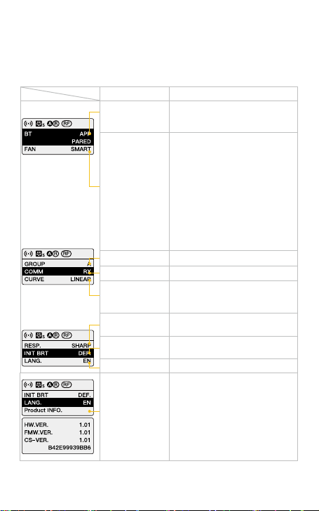
None grouping status. The product defaults to the factory
status, and will not be aected by other groups.
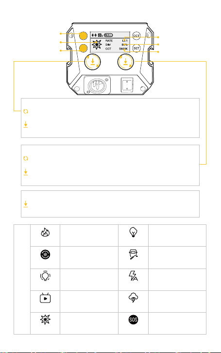
If the icon ashes, it means that the internal temperature of the
product is too high, and cooling measures need to be taken. If
the icon disappears, it means that the operation is normal.
③ Group Status Icon
④ Product Overheated Alarm Icon
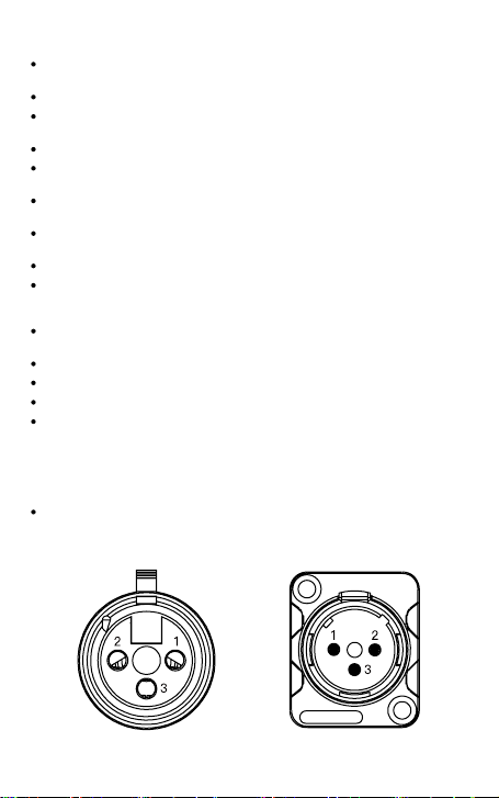
A stands for Group A. There are fteen groups (A~O). T
stands for Tx.
A stands for Group A. There are fteen groups (A~O). R
stands for Rx.
A stands for Group A. There are fteen groups (A~O). TR
stands for TxRx.
Operation Instructions
1. Please remove the COB protective cover before using the light.
2. Turn on the lamp: After conrming that the power connection is normal,
press the switch to "-", and the screen will display the brand and product
module, and then enter the operation interface. (Default mode: CCT)
3. Turn o the lamp: press the switch to "o" to turn o the power switch.
1. Status Icon Description
After selecting wireless connection in Settings menu, the
icon will be displayed dynamically.
The icon is always on to indicate successful pairing with
mobile APP.
The icon disappears to indicate mobile APP pairing failure, or
the product is unpaired.
Smart Mode. The product will adjust the fan speed according
to the internal detected temperature to ensure that it is in
optimal working condition.
Quiet Mode. The fan keeps running at low speed for minimum
noise, and overheating protection will be activated if the
product temperature is higher than the alarm value.
Performance Mode. Fan runs at the highest speed to ensure
heat dissipation.
① APP Connection Status Icon
② Fan Status Icon