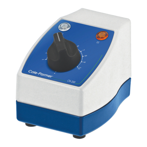
Cole Parmer Electrothermal MC810B User manual

Digital Heating
Controller
MC810B, MC810BX1
Instruction Manual
M6493 / Version 10.5

Please take your time to read this Instruction manual in order to understand the safe and
correct use of your new Electrothermal product.
It is recommended the responsible Body for the use of this equipment reads this instruction
manual and ensures the user(s) are suitably trained in its operation.
Contents Page
Section 1 Introduction 3
Section 2 Symbols and using this Instruction Manual 4
Section 3 Safety Information 5
Section 4 Unpacking and Contents 7
Section 5 Installation 8
Section 6 Environmental Protection 9
Section 7 Equipment Operation 10
Section 8 Technical Specication 18
Section 9 Maintenance 19
Section 10 Spares and Accessories 21
Section 11 Customer Support 21
Section 12 Notes 22
Section 13 EC Declaration of Conformity 23
© The copyright of this instruction manual is the property of Cole-Parmer Limited. This instruction manual is supplied
by Cole-Parmer Limited on the express understanding that it is to be used solely for the purpose for which it is supplied.
It may not be copied, used or disclosed to others in whole or part for any purpose except as authorised in writing by
Cole-Parmer Limited. Cole-Parmer Limited reserves the right to alter, change or modify this document without prior
notication.
In the interest of continued development Cole-Parmer Limited reserve the right to alter or modify the design and / or
assembly process of their products without prior notication.
This product is manufactured in Great Britain by Electrothermal, part of the Cole-Parmer Group of companies.
Cole-Parmer Ltd.
Beacon Road,
Stone,
Staffordshire,
ST15 0SA,
United Kingdom
Tel: +44 (0)1785 812121
2

1.1 INTRODUCTION
1.1. The Electrothermal MC810B Digital Controller provides a convenient means of
temperature control, using microprocessor techniques to give ease of operation and
good accuracy. It can be used either in ON/OFF mode with the hysteresis loop
controlling power switching or it can be used as a PID (Proportional, Integrated,
Derivative) controller. Alternatively it may be used simply as a temperature
measuring device.
1.2. Temperature sensing is performed by a plug-in platinum resistance probe. The
sample temperature is displayed on the LED display. This product is suitable for
bench and retort stand mounting or wall mounting using the bracket and screws
provided.
1.3. The MC810B has a short mains output lead with an IEC socket to connect it to the
resistive load. An accessory extension mains lead is available where remote
operation is required (e.g. in a fume extraction unit).
1.4. The MC810B controller must be used in conjunction with a suitable heating or
cooling device e.g. mantle, electric Bunsen or hotplate. For cooling applications
please contact your distributor / suppler or contact Cole-Parmer at the address in
section 11. Customer Support.
3

2. SYMBOLS AND USING THIS INSTRUCTION MANUAL
2.1. Throughout this Instruction manual the following symbols are shown to identify
conditions which pose a hazard to the user, or to identify actions that should be
observed. These symbols are also shown on the product, or its packaging. When a
symbol is shown next to a paragraph or statement it is recommended the user takes
particular note of that instruction in order to prevent damage to the equipment or to
prevent injury to one’s self or other people.
The Responsible Body and the Operator should read and be familiar with this
instruction manual in order to preserve the protection afforded by the
equipment.
To prevent injury or equipment damage it is the manufacturer’s
recommendation that all persons using this equipment are suitably trained
before use.
2.2. Symbols Dened.
Caution, risk of danger. See note or adjacent symbol.
Protective conductor terminal to be earthed.
(Do not loosen or disconnect).
Caution / Risk of electric shock.
Recyclable Packaging Material.
Do not dispose of product in normal domestic waste.
Bio Chemical Hazard. Caution required. May require
decontamination.
Refer to Instruction manual.
Info / Enter button
Modify Setpoint 1 / Decrease button
Increase / Modify Setpoint 2 button.
Exit / Standby button.
Alarm (This feature is not available on MC810B).
4
Page 4 of 24 M6493 Issue 10.3
2. SYMBOLS AND USING THIS INSTRUCTION BOOK.
2.1. Throughout this Instruction book the following symbols are shown to identify
conditions which pose a hazard to the user, or to identify actions that should be
observed. These symbols are also shown on the product, or its packaging. When a
symbol is shown next to a paragraph or statement it is recommended the user takes
particular note of that instruction in order to prevent damage to the equipment or to
prevent injury to one’s self or other people.
The Responsible Body and the Operator should read and be familiar with this
Instruction book in order to preserve the protection afforded by the equipment.
To prevent injury or equipment damage it is the manufacturer’s
recommendation that all persons using this equipment are suitably trained
before use.
2.2. Symbols Defined.
Caution, risk of danger. See note or adjacent symbol.
Protective conductor terminal to be earthed.
(Do not loosen or disconnect).
Caution / Risk of electric shock.
Recyclable Packaging Material.
Do not dispose of product in normal domestic waste.
Bio Chemical Hazard. Caution required. May require
decontamination.
Refer to Instruction book.
Info / Enter button
Modify Setpoint 1 / Decrease button
Increase / Modify Setpoint 2 button.
Exit / Standby button.
Alarm (This feature is not available on MC810B).

5
3. SAFETY INFORMATION
This product has been designed for safe operation when used as detailed in accordance
with the manufacturer’s instructions.
NOTE: Failure to use this equipment in accordance with this instruction manual may
compromise your basic safety protection afforded by the equipment and may invalidate
the warranty / guarantee. The warranty / guarantee does not cover damaged caused by
faulty installation or misuse of the equipment.
3.1. Prevention of Fire and Electric shock.
To prevent a risk of re or electric shock, do not open your product case
without authorisation. Only qualied Service personnel should attempt to
repair this Controller.
Only replace fuses with the type as listed in Technical Specication section
(See fuse type and rating).
Ensure the Mains Power Supply conforms to rating found on the data plate
located on the base of this product.
Never operate this equipment without connection to earth / ground. Ensure
the mains supply voltage is correctly earthed / grounded in accordance with
current area legislation.
Do not install or remove any heating apparatus from the controller
whilst power is applied.
3.2. General Safe Operating Practice.
Always follow good laboratory practice when using this equipment. Give
due recognition to your company’s safety and legislative health & safety
procedures and all associated legislation applicable to your areas of operation.
Check laboratory procedures for substances being heated and ensure all
hazards (e.g. explosion, implosion or the release of toxic or ammable gases)
that might arise have been suitably addressed before proceeding. When
heating certain substances the liberation of hazardous gases may require the
use of a fume cupboard or other means of extraction.
Ensure equipment is used on a clean, dry, non-combustible, solid work surface
with at least 300mm suitable clearance all around from other equipment.
Do not position the product so that it is difcult to disconnect from the mains
supply.
Do not immerse the controller in water or uids.
Do not spill substances onto this unit. If spillage does occur, disconnect
unit from mains supply and follow instructions as detailed in Section
‘Maintenance’.
To prevent electronic overheat and potential re, do not cover this product
when connected to the mains power supply.
Page 5 of 24 M6493 Issue 10.3
3. SAFETY INFORMATION.
This product has been designed for safe operation when used as detailed in
accordance with the manufacturer’s instructions.
NOTE: Failure to use this equipment in accordance with this instruction book may
compromise your basic safety protection afforded by the equipment and may
invalidate the warranty / guarantee. The warranty / guarantee does not cover
damaged caused by faulty installation or misuse of the equipment.
3.1. Prevention of Fire and Electric shock.
To prevent a risk of fire or electric shock,
DO NOT
open your
product case without authorisation. Only qualified Service
personnel should attempt to repair this Controller.
Replace fuses only with the type as listed in section, Parts and
Accessories and Technical Specifications. (See fuse type and
rating).
Ensure the Mains Power Supply conforms to rating found on the
data plate located on the base of this product.
Never
Operate this equipment with out connection to earth /
ground. Ensure the mains supply voltage is correctly earthed /
grounded in accordance with current area legislation.
Do not
install or remove any heating apparatus from the controller
whilst power is applied.
3.2. General Safe Operating Practice.
Always follow good laboratory practice when using this
equipment. Give due recognition to your company’s safety and
legislative health & safety procedures and all associated legislation
applicable to your areas of operation. Check laboratory procedures
for substances being heated and ensure all hazards (e.g. explosion,
implosion or the release of toxic or flammable gases) that might
arise have been suitably addressed before proceeding. When
heating certain substances the liberation of hazardous gases may
require the use of a fume cupboard or other means of extraction.
Ensure equipment is used on a clean, dry, non-combustible, solid
work surface with at least 300mm suitable clearance all around
from other equipment.
Do not
position the product so that it is difficult to disconnect from
the mains supply.
Do not
immerse unit in water or fluids.
Do not
spill substances onto this unit. If spillage does occur,
disconnect unit from mains supply and follow instructions as
detailed in Section ‘Maintenance’.
To prevent electronic overheat and potential fire
Do not cover this product when connected to the mains power
supply.
It is
not
recommended to leave any heating apparatus unattended
during operation.
Only use Original Equipment manufacture’s spares and
accessories. Ref Section 11.

6
It is not recommended to leave any heating apparatus unattended
during operation.
Only use original equipment manufacturer’s spares and accessories. Refer to
Section 10.
The equipment is not spark, ame or explosion proof and has not been
designed for use in hazardous areas in terms of BSEN 60079-14:1997.
Keep ammable, low ash point substances away from heating apparatus.
Do not operate or handle any part of this product with wet hands.
Keep the Mains Plug and Lead set cable away from the
heating apparatus being controlled.
Refer to Instructions manual / product data label for the resistive load
of equipment to ensure controller is suitable for application.
Always observe the manufacturer’s operating and safety instructions for the
equipment to be connected to the controller.
NOTE: if this product is not used in accordance with the manufacturer’s instructions
then the basic safety protection afforded by the equipment may not be preserved and
the guarantee invalidated.
Page 5 of 24 M6493 Issue 10.3
3. SAFETY INFORMATION.
This product has been designed for safe operation when used as detailed in
accordance with the manufacturer’s instructions.
NOTE: Failure to use this equipment in accordance with this instruction book may
compromise your basic safety protection afforded by the equipment and may
invalidate the warranty / guarantee. The warranty / guarantee does not cover
damaged caused by faulty installation or misuse of the equipment.
3.1. Prevention of Fire and Electric shock.
To prevent a risk of fire or electric shock,
DO NOT
open your
product case without authorisation. Only qualified Service
personnel should attempt to repair this Controller.
Replace fuses only with the type as listed in section, Parts and
Accessories and Technical Specifications. (See fuse type and
rating).
Ensure the Mains Power Supply conforms to rating found on the
data plate located on the base of this product.
Never
Operate this equipment with out connection to earth /
ground. Ensure the mains supply voltage is correctly earthed /
grounded in accordance with current area legislation.
Do not
install or remove any heating apparatus from the controller
whilst power is applied.
3.2. General Safe Operating Practice.
Always follow good laboratory practice when using this
equipment. Give due recognition to your company’s safety and
legislative health & safety procedures and all associated legislation
applicable to your areas of operation. Check laboratory procedures
for substances being heated and ensure all hazards (e.g. explosion,
implosion or the release of toxic or flammable gases) that might
arise have been suitably addressed before proceeding. When
heating certain substances the liberation of hazardous gases may
require the use of a fume cupboard or other means of extraction.
Ensure equipment is used on a clean, dry, non-combustible, solid
work surface with at least 300mm suitable clearance all around
from other equipment.
Do not
position the product so that it is difficult to disconnect from
the mains supply.
Do not
immerse unit in water or fluids.
Do not
spill substances onto this unit. If spillage does occur,
disconnect unit from mains supply and follow instructions as
detailed in Section ‘Maintenance’.
To prevent electronic overheat and potential fire
Do not cover this product when connected to the mains power
supply.
It is
not
recommended to leave any heating apparatus unattended
during operation.
Only use Original Equipment manufacture’s spares and
accessories. Ref Section 11.
Page 6 of 24 M6493 Issue 10.3
The equipment is not spark, flame or explosion proof and has not
been designed for use in hazardous areas in terms of BSEN 60079-
14:1997. Keep flammable, low flash point substances away from
heating apparatus.
Do not
operate or handle any part of this product with wet hands.
Keep the Mains Plug and Lead set cable away from the
heating apparatus being controlled.
Refer to Instructions book / product data label for the resistive load
of equipment to ensure controller is suitable for application.
Always observe the Manufacturer’s operating and safety
instructions for the equipment to be connected to the controller.
NOTE: if this product is not used in accordance with the Manufacturer’s Instructions then the basic
safety protection afforded by the equipment may not be preserved and the guarantee invalidated.

7
Page 7 of 24 M6493 Issue 10.3
4. UNPACKING AND CONTENTS.
Item
No
Description
Qty
1
Mains cord and moulded IEC plug and lead set.
(May be different from illustration).
As
Req
2
MC810B MKII Digital Controller.
1
3
Instruction Book
1
4
Wall fixing Bkt x 1 and screws x 2 – per bag.
1
5
Temperature Probe
1
For future reference
please record your
products Serial and
Model Numbers.
Serial Number Model Number
4. UNPACKING AND CONTENTS

8
5. INSTALLATION
5.1. Electrical safety and Installation
5.2. This equipment is designed for safe operation under the following conditions:-
• Indoor use.
• Altitude up to 2000 meters.
• Temperatures between -10°C and +50°C.
• Maximum relative humidity 80% for temperatures up to 31°C decreasing
linearly to 50% relative humidity at 40°C.
• Mains supply voltage uctuations up to ± 10% of the nominal voltage.
• Transient overvoltages typically present on the mains supply. (Overvoltage
category II).
• Applicable rated pollution degree 2.
5.3. This equipment must be earthed / grounded to a xed earth / grounded mains
socket outlet. The mains supply is to be earthed / grounded in accordance with
current legislation.
5.4. Ensure only the correct rated mains input fuses are tted. (Where applicable ensure
the correct mains cable fuse if tted). See Technical Specication, Section 8 of this
Instruction manual.
5.5. Check the voltage on the product data label of this unit. Ensure the rating conforms
to your local supply. Only connect to resistive loads = 1500Watts @230V~AC or
750Watts @ 115V~AC. Refer to Technical Specification, Section 8 of this Instruction
manual.
5.6. This product must be connected to a mains supply source which incorporates an
RCD or GFCI device.
5.7. The unit is supplied with a moulded mains cord and plug set wired as follows:-
Green /Yellow or Green = Earth / Ground
Blue or White = Neutral
Brown or Black = Live / line hot.
5.8. If the controller is to be used on a retort rod, make sure it isn’t positioned over any
heating apparatus.
5.9. If using the wall mounting bracket provided, carefully mark and drill two suitable
holes using the bracket as a template. Ensure there are no cables etc buried in the wall.
Plug the holes with suitable raw plugs (not supplied) and fasten the bracket to the
wall in the correct orientation using the screws provided. Place the controller over the
bracket.
Page 8 of 24 M6493 Issue 10.3
5. INSTALLATION.
5.1. Electrical safety and Installation.
5.2. This equipment is designed for safe operation under the following conditions:-
•Indoor use.
•Altitude up to 2000 meters.
•Temperatures between -10°C and +50°C.
•Maximum relative humidity 80% for temperatures up to 31°C decreasing
linearly to 50% relative humidity at 40°C.
•Mains supply voltage fluctuations up to ± 10% of the nominal voltage.
•Transient overvoltages typically present on the mains supply. (Overvoltage
category II).
•Applicable rated pollution degree 2.
5.3. This equipment must be earthed / grounded to a fixed earth / grounded mains
socket outlet. The mains supply is to be earthed / grounded in accordance with
current legislation.
5.4. Ensure only the correct rated mains input fuses are fitted. (Where applicable ensure
the correct mains cable fuse if fitted). See Technical Specification, Section 8 of this
Instruction book.
5.5. Check the voltage on the product data label of this unit. Ensure the rating conforms
to your local supply. Only connect to resistive loads = 1500Watts @ 230V~AC or
750Watts @ 115V~AC. Refer to Technical Specification, Section 8 of this Instruction
book.
5.6. This product must be connected to a mains supply source which incorporates an
RCD or GFCI device.
5.7. The unit is supplied with a moulded mains cord and plug set wired as follows:-
Green /
Yellow
or Green =Earth / Ground
Blue
or
White
=
Neutral
Brown
or
Black
=
Live / line hot.
5.8. If the controller is to be used on a retort rod, make sure it isn’t positioned over any
heating apparatus.
5.9. If using the wall mounting bracket provided, carefully mark and drill two
suitable holes using the bracket as a template. Ensure there are now cables etc
buried in the wall. Plug the holes with raw plugs and fasten the bracket to the wall in
the correct orientation using the screws provided. Place the controller over the
bracket.

6. ENVIRONMENTAL PROTECTION
6.1. Maximum consideration has to be given to environmental issues within the design and
manufacturing process without compromising end product performance and value.
6.2. Packaging materials have been selected such that they may be sorted for
recycling.
6.3. At the end of your product and accessories life, it must not be discarded as
domestic waste. Ref: EU Directive 2012/19/EU on Waste Electrical and Electronic
Equipment Directive (WEEE). Please contact your distributor / supplier for further
information. For end users outside of the EU consult applicable regulations.
6.4. This product should only be dismantled for recycling by an authorised recycling
company.
This product and accessories must be accompanied by a completed
Decontamination Certicate prior to any Disposal. Copies of the Certicate are
available from Distributor/Manufacturer.
9
Page 9 of 24 M6493 Issue 10.3
6. ENVIRONMENTAL PROTECTION.
6.1. Maximum consideration to environmental issues within the design and
manufacturing process without compromising end product performance and value.
6.2. Packaging materials have been selected such that they may be sorted for
recycling.
6.3. At the end of your product and accessories life, it must not be discarded as
domestic waste. Ref: EU Directive 2002/96/EC on Waste Electrical and Electronic
Equipment Directive (WEEE). Please contact your distributor / supplier for further
information. For end users outside of the EU consult applicable regulations.
6.4. This product should only be dismantled for recycling by an authorised recycling
company.
This product and accessories must be accompanied by a completed
Decontamination Certificate prior to any disposal. Copies of the Certificate are
available from your distributor of Bibby Scientific products, or you may copy
and enlarge from ‘Appendix A’ of this instruction book.
Bibby Scientific’s Electrothermal branded product range is registered with the Environment Agency under the name of as
Electrothermal Engineering Limited as being a producer of WEEE (Waste Electronic and Electrical Equipment) through b2b
Compliance,an authorised waste collection compliance scheme.

7. EQUIPMENT OPERATION
7.1. The MC810B controller has been designed for easy operation. The illustrations
below show detailed layouts of this control unit.
1 Instruction Manual label (refer to this Manual).
2 Mains input IEC socket with fuses.
3 3 digit LED display
4 Orange Neon power on indication lamp.
5 Exit / Standby button
6 Mains Output IEC plug.
7 Earth protective conduct terminal.
8 Temperature probe
9 On / Off, I/O power switch.
10 Retort rod clamp
11 Data plate label
12 Wall bracket clamp.
13 5 Pin DIN socket for temperature probe.
10
Check the data plate label and ensure your mains electrical supply voltage is
compatible with this product.
Page 10 of 24 M6493 Issue 10.3
7. PRODUCT OPERATION.
7.1. The MC810B controller has been designed for easy operation. The illustrations
below show detailed layouts of this control unit.
1
Instruction book label (refer to this book).
2
Mains input IEC socket with fuses.
3
3 digit LED display
4
Orange Neon power on indication lamp.
5
Exit / Standby button
6
Mains Output IEC plug.
7
Earth protective conduct terminal.
8
Temperature probe
9
On / Off, I/O power switch.
10
Retort rod clamp
11
Data plate label
12
Wall bracket clamp.
13
5 Pin DIN socket for temperature probe.
Check the data plate label and ensure your mains electrical supply voltage is
compatible with this product.

7.2. Connection
7.2.1. Plug in the temperature probe to the 5 pin DIN socket. Place the temperature probe
into the sample ensuring that at least 40mm of the probe tip is in contact with the
sample. Ensure the temperature probe is correctly plugged into the 5-pin DIN socket at
the rear of the MC810B Controller.
Note: Should the temperature probe become disconnected or fail open circuit,
the display will indicate “or” and a dot next to the alarm symbol will illuminate.
7.2.2. Connect the IEC output plug to your heating apparatus as illustrated.
7.2.3. Connect to the mains electricity supply. Turn on using the On / Off Power switch. The
amber neon will illuminate when power is being supplied to the output. Depending on
the operating mode, the amber neon may be on continuously, or switch on and off.
7.3. Control Modes Explained
7.3.1. Basic On / Off Controller
The On / Off controller output has only two states. Fully on and fully off. Fully on
is when the temperature is anywhere below set point, and fully off, when the
temperature is anywhere above the desired set point.
7.3.2. On-Off Controller plus Hysteresis
To prevent detrimental control chattering as the temperature crosses the set point, an
On / Off differential or ‘hysteresis’ can be added to the controller function.
When a hysteresis value is entered (for example, say 3°C), the controller will switch off
once the set point temperature has been reached and will not switch back on again
until the measured temperature falls 3°C below the set point.
For example, in a heating application, with a 150°C set point and a 3°C hysteresis value
entered, the controller will switch off at 150°C (there may be some overshoot) and will
not come back on again until the temperature falls to 147°C.
The hysteresis gure should be set to give improved control of temperature without
excessive chatter. The amount of hysteresis determines the minimum temperature
variation possible, although process characteristics will add to this differential.
On / Off functions are only accurate when the heating mass is relatively large, and the
heater will cause overshoot and wide variations in temperature.
11
Page 11 of 24 M6493 Issue 10.3
7.2. Connection.
7.2.1. Plug in the temperature probe to the 5 pin DIN socket. Place the temperature
probe into the sample ensuring that at least 40mm of the probe tip is in contact
with the sample. Ensure the temperature probe is correctly plugged into the 5-
pin DIN socket at the rear of the MC810B Controller.
Note: Should the temperature probe become disconnected or fail open circuit,
the display will indicate “or” and a dot next to the alarm symbol will illuminate.
7.2.2. Connect the IEC output plug to your heating apparatus as illustrated.
or
7.2.3. Connect to the mains electricity supply. Turn on using the On / Off Power
switch. The amber neon will illuminate when power is being supplied to the
output. Depending on the operating mode, the amber neon may be on
continuously, or switch on and off.
7.3. Control Modes Explained.
7.3.1. Basic On / Off Controller.
The On / Off controller output has only two states. Fully on and fully off. Fully
on is when the temperature is anywhere below set point, and fully off, when
the temperature is anywhere above the desired set point.
7.3.2. On-Off Controller plus Hysteresis.
To prevent detrimental control chattering as the temperature crosses the set
point, an On / Off differential or ‘hysteresis’ can be added to the controller
function.
When a hysteresis value is entered (for example, say 3°C), the controller will
switch off once the set point temperature has been reached and will not
switch back on again until the measured temperature falls 3°C below the set
point.
For example, in a heating application, with a 150°C set point and a 3°C
hysteresis value entered, the controller will switch off at 150°C (there may be
some overshoot) and will not come back on again until the temperature falls
to 147°C.
The hysteresis figure should be set to give improved control of temperature
without excessive chatter. The amount of hysteresis determines the minimum
temperature variation possible, although process characteristics will add to
this differential.
On / Off functions are only accurate when the heating mass is relatively large,
and the heater will cause overshoot and wide variations in temperature.

7.3.3. Proportional, Integral and Derivative Control
A proportional controller continuously adjusts the power, so the heat input to the
process is approximately in balance with the process heat requirements in order to
maintain a stable temperature. The range of temperature over which power is adjusted
is from 0% to 100%. This temperature range is called the ‘Proportional Band’. The
proportional band is adjustable for differing process conditions (zero proportional band
returns the controller to basic on / off control).
The temperature difference between the stabilised temperature and the set point is
called the ‘Offset’. The offset can be reduced by adjusting the integral term of the PID
controller. This is achieved using the integrative action time and integrative action reset.
A derivative function can be combined with the proportional controller to provide
the controller with the ability to shift the proportional band either up to or down to
compensate for rapidly changing temperature (i.e. when an oven door is opened or
cooler uid is introduced into a controlled vessel). The derivative function increases the
controller gain during temperature changes, and can help to reduce overshoot on
start-up.
Hence, a three-mode PID controller combines the proportional, integral and derivative
actions, to allow the set point temperature to be approached relatively smoothly with
minimal overshoot.
7.4. Front Panel Controls
The MC810B controller has four front panel keys as described below.
7.4.1. The key is used to increase the value of the parameter shown on the display or
to scroll through the parameter menu.
7.4.2. The key is used to decrease the value of the parameter shown on the display
or to scroll through the parameter menu.
7.4.3. The key is a dual function key. It is used to display and store the value of the
selected parameter when in ‘Programming’ mode. When used with the
it is used to display the ‘Setpoint’ value.
7.4.4. The is an ‘Exit / Stand-by button. Press of 3 seconds to turn unit on or off.
7.5. Operating Modes
7.5.1. The MB810B has two modes of operation: Function mode and Programming mode.
The unit enters Function mode immediately following power up in auto test phase.
In Function mode the display shows the temperature measured by the temperature
sensing probe. The output power will also be switched on or off as appropriate. If the
output power is on, the amber neon indicator on the front panel will be illuminated.
The only parameter which can be altered in the function mode is the set-point. See
7.7.1.
7.5.2. In Programming mode, all the other parameters apart from set-point can be altered. To
gain access to the programming mode from Function mode, press the keys
and . Keep them pressed for ve seconds. The output power is always
12
Page 12 of 24 M6493 Issue 10.3
7.3.3. Proportional, Integral and Derivative Control.
A proportional controller continuously adjusts the power, so the heat input to
the process is approximately in balance with the process heat requirements
in order to maintain a stable temperature. The range of temperature over
which power is adjusted is from 0% to 100%. This temperature range is
called the ‘Proportional Band’. The proportional band is adjustable for
differing process conditions (zero proportional band returns the controller to
basic on / off control).
The temperature difference between the stabilised temperature and the set
point is called the ‘Offset’. The offset can be reduced by adjusting the integral
term of the PID controller. This is achieved using the integrative action time
and integrative action reset.
A derivative function can be combined with the proportional controller to
provide the controller with the ability to shift the proportional band either up to
or down to compensate for rapidly changing temperature (i.e. when an oven
door is opened or cooler fluid is introduced into a controlled vessel). The
derivative function increases the controller gain during temperature changes,
and can help to reduce overshoot on start-up.
Hence, a three-mode PID controller combines the proportional, integral and
derivative actions, to allow the set point temperature to be approached
relatively smoothly with minimal overshoot.
7.4. Front Panel Controls
The MC810B controller has four front panel keys as described below.
7.4.1. The
key is used to increase the value of the parameter shown on
the display or to scroll through the parameter menu.
7.4.2. The key is used to decrease the value of the parameter shown on
the display or to scroll through the parameter menu.
7.4.3. The key is a dual function key. It is used to display and store the
value of the selected parameter when in ‘Programming’ mode. When used with
the it is used to display the ‘Setpoint’ value.
7.4.4. The is an ‘Exit / Stand-by button. Press of 3 seconds to turn unit on
or off.
7.5. Operating Modes.
7.5.1. The MB810B has two modes of operation: Function mode and Programming
mode. The unit enters Function mode immediately following power up in auto
test phase. In Function mode the display shows the temperature measured by
the temperature sensing probe. The output power will also be switched on or off
as appropriate. If the output power is on, the amber neon indicator on the front
panel will be illuminated. The only parameter which can be altered in the
function mode is the set-point. See 7.7.1
7.5.2. In Programming mode, all the other parameters apart from set-point can be
altered. To gain access to the programming mode from Function mode, press
the keys and . Keep them pressed for five seconds. The
output power is always off when in programming mode. If approximately 25
seconds elapse while in programming mode with out a key being pressed the
Page 12 of 24 M6493 Issue 10.3
7.3.3. Proportional, Integral and Derivative Control.
A proportional controller continuously adjusts the power, so the heat input to
the process is approximately in balance with the process heat requirements
in order to maintain a stable temperature. The range of temperature over
which power is adjusted is from 0% to 100%. This temperature range is
called the ‘Proportional Band’. The proportional band is adjustable for
differing process conditions (zero proportional band returns the controller to
basic on / off control).
The temperature difference between the stabilised temperature and the set
point is called the ‘Offset’. The offset can be reduced by adjusting the integral
term of the PID controller. This is achieved using the integrative action time
and integrative action reset.
A derivative function can be combined with the proportional controller to
provide the controller with the ability to shift the proportional band either up to
or down to compensate for rapidly changing temperature (i.e. when an oven
door is opened or cooler fluid is introduced into a controlled vessel). The
derivative function increases the controller gain during temperature changes,
and can help to reduce overshoot on start-up.
Hence, a three-mode PID controller combines the proportional, integral and
derivative actions, to allow the set point temperature to be approached
relatively smoothly with minimal overshoot.
7.4. Front Panel Controls
The MC810B controller has four front panel keys as described below.
7.4.1. The key is used to increase the value of the parameter shown on
the display or to scroll through the parameter menu.
7.4.2. The
key is used to decrease the value of the parameter shown on
the display or to scroll through the parameter menu.
7.4.3. The key is a dual function key. It is used to display and store the
value of the selected parameter when in ‘Programming’ mode. When used with
the it is used to display the ‘Setpoint’ value.
7.4.4. The is an ‘Exit / Stand-by button. Press of 3 seconds to turn unit on
or off.
7.5. Operating Modes.
7.5.1. The MB810B has two modes of operation: Function mode and Programming
mode. The unit enters Function mode immediately following power up in auto
test phase. In Function mode the display shows the temperature measured by
the temperature sensing probe. The output power will also be switched on or off
as appropriate. If the output power is on, the amber neon indicator on the front
panel will be illuminated. The only parameter which can be altered in the
function mode is the set-point. See 7.7.1
7.5.2. In Programming mode, all the other parameters apart from set-point can be
altered. To gain access to the programming mode from Function mode, press
the keys and . Keep them pressed for five seconds. The
output power is always off when in programming mode. If approximately 25
seconds elapse while in programming mode with out a key being pressed the
Page 12 of 24 M6493 Issue 10.3
7.3.3. Proportional, Integral and Derivative Control.
A proportional controller continuously adjusts the power, so the heat input to
the process is approximately in balance with the process heat requirements
in order to maintain a stable temperature. The range of temperature over
which power is adjusted is from 0% to 100%. This temperature range is
called the ‘Proportional Band’. The proportional band is adjustable for
differing process conditions (zero proportional band returns the controller to
basic on / off control).
The temperature difference between the stabilised temperature and the set
point is called the ‘Offset’. The offset can be reduced by adjusting the integral
term of the PID controller. This is achieved using the integrative action time
and integrative action reset.
A derivative function can be combined with the proportional controller to
provide the controller with the ability to shift the proportional band either up to
or down to compensate for rapidly changing temperature (i.e. when an oven
door is opened or cooler fluid is introduced into a controlled vessel). The
derivative function increases the controller gain during temperature changes,
and can help to reduce overshoot on start-up.
Hence, a three-mode PID controller combines the proportional, integral and
derivative actions, to allow the set point temperature to be approached
relatively smoothly with minimal overshoot.
7.4. Front Panel Controls
The MC810B controller has four front panel keys as described below.
7.4.1. The key is used to increase the value of the parameter shown on
the display or to scroll through the parameter menu.
7.4.2. The key is used to decrease the value of the parameter shown on
the display or to scroll through the parameter menu.
7.4.3. The
key is a dual function key. It is used to display and store the
value of the selected parameter when in ‘Programming’ mode. When used with
the it is used to display the ‘Setpoint’ value.
7.4.4. The is an ‘Exit / Stand-by button. Press of 3 seconds to turn unit on
or off.
7.5. Operating Modes.
7.5.1. The MB810B has two modes of operation: Function mode and Programming
mode. The unit enters Function mode immediately following power up in auto
test phase. In Function mode the display shows the temperature measured by
the temperature sensing probe. The output power will also be switched on or off
as appropriate. If the output power is on, the amber neon indicator on the front
panel will be illuminated. The only parameter which can be altered in the
function mode is the set-point. See 7.7.1
7.5.2. In Programming mode, all the other parameters apart from set-point can be
altered. To gain access to the programming mode from Function mode, press
the keys and . Keep them pressed for five seconds. The
output power is always off when in programming mode. If approximately 25
seconds elapse while in programming mode with out a key being pressed the
Page 12 of 24 M6493 Issue 10.3
7.3.3. Proportional, Integral and Derivative Control.
A proportional controller continuously adjusts the power, so the heat input to
the process is approximately in balance with the process heat requirements
in order to maintain a stable temperature. The range of temperature over
which power is adjusted is from 0% to 100%. This temperature range is
called the ‘Proportional Band’. The proportional band is adjustable for
differing process conditions (zero proportional band returns the controller to
basic on / off control).
The temperature difference between the stabilised temperature and the set
point is called the ‘Offset’. The offset can be reduced by adjusting the integral
term of the PID controller. This is achieved using the integrative action time
and integrative action reset.
A derivative function can be combined with the proportional controller to
provide the controller with the ability to shift the proportional band either up to
or down to compensate for rapidly changing temperature (i.e. when an oven
door is opened or cooler fluid is introduced into a controlled vessel). The
derivative function increases the controller gain during temperature changes,
and can help to reduce overshoot on start-up.
Hence, a three-mode PID controller combines the proportional, integral and
derivative actions, to allow the set point temperature to be approached
relatively smoothly with minimal overshoot.
7.4. Front Panel Controls
The MC810B controller has four front panel keys as described below.
7.4.1. The key is used to increase the value of the parameter shown on
the display or to scroll through the parameter menu.
7.4.2. The key is used to decrease the value of the parameter shown on
the display or to scroll through the parameter menu.
7.4.3. The key is a dual function key. It is used to display and store the
value of the selected parameter when in ‘Programming’ mode. When used with
the it is used to display the ‘Setpoint’ value.
7.4.4. The is an ‘Exit / Stand-by button. Press of 3 seconds to turn unit on
or off.
7.5. Operating Modes.
7.5.1. The MB810B has two modes of operation: Function mode and Programming
mode. The unit enters Function mode immediately following power up in auto
test phase. In Function mode the display shows the temperature measured by
the temperature sensing probe. The output power will also be switched on or off
as appropriate. If the output power is on, the amber neon indicator on the front
panel will be illuminated. The only parameter which can be altered in the
function mode is the set-point. See 7.7.1
7.5.2. In Programming mode, all the other parameters apart from set-point can be
altered. To gain access to the programming mode from Function mode, press
the keys and . Keep them pressed for five seconds. The
output power is always off when in programming mode. If approximately 25
seconds elapse while in programming mode with out a key being pressed the
Page 12 of 24 M6493 Issue 10.3
7.3.3. Proportional, Integral and Derivative Control.
A proportional controller continuously adjusts the power, so the heat input to
the process is approximately in balance with the process heat requirements
in order to maintain a stable temperature. The range of temperature over
which power is adjusted is from 0% to 100%. This temperature range is
called the ‘Proportional Band’. The proportional band is adjustable for
differing process conditions (zero proportional band returns the controller to
basic on / off control).
The temperature difference between the stabilised temperature and the set
point is called the ‘Offset’. The offset can be reduced by adjusting the integral
term of the PID controller. This is achieved using the integrative action time
and integrative action reset.
A derivative function can be combined with the proportional controller to
provide the controller with the ability to shift the proportional band either up to
or down to compensate for rapidly changing temperature (i.e. when an oven
door is opened or cooler fluid is introduced into a controlled vessel). The
derivative function increases the controller gain during temperature changes,
and can help to reduce overshoot on start-up.
Hence, a three-mode PID controller combines the proportional, integral and
derivative actions, to allow the set point temperature to be approached
relatively smoothly with minimal overshoot.
7.4. Front Panel Controls
The MC810B controller has four front panel keys as described below.
7.4.1. The key is used to increase the value of the parameter shown on
the display or to scroll through the parameter menu.
7.4.2. The key is used to decrease the value of the parameter shown on
the display or to scroll through the parameter menu.
7.4.3. The key is a dual function key. It is used to display and store the
value of the selected parameter when in ‘Programming’ mode. When used with
the it is used to display the ‘Setpoint’ value.
7.4.4. The
is an ‘Exit / Stand-by button. Press of 3 seconds to turn unit on
or off.
7.5. Operating Modes.
7.5.1. The MB810B has two modes of operation: Function mode and Programming
mode. The unit enters Function mode immediately following power up in auto
test phase. In Function mode the display shows the temperature measured by
the temperature sensing probe. The output power will also be switched on or off
as appropriate. If the output power is on, the amber neon indicator on the front
panel will be illuminated. The only parameter which can be altered in the
function mode is the set-point. See 7.7.1
7.5.2. In Programming mode, all the other parameters apart from set-point can be
altered. To gain access to the programming mode from Function mode, press
the keys and . Keep them pressed for five seconds. The
output power is always off when in programming mode. If approximately 25
seconds elapse while in programming mode with out a key being pressed the
Page 12 of 24 M6493 Issue 10.3
7.3.3. Proportional, Integral and Derivative Control.
A proportional controller continuously adjusts the power, so the heat input to
the process is approximately in balance with the process heat requirements
in order to maintain a stable temperature. The range of temperature over
which power is adjusted is from 0% to 100%. This temperature range is
called the ‘Proportional Band’. The proportional band is adjustable for
differing process conditions (zero proportional band returns the controller to
basic on / off control).
The temperature difference between the stabilised temperature and the set
point is called the ‘Offset’. The offset can be reduced by adjusting the integral
term of the PID controller. This is achieved using the integrative action time
and integrative action reset.
A derivative function can be combined with the proportional controller to
provide the controller with the ability to shift the proportional band either up to
or down to compensate for rapidly changing temperature (i.e. when an oven
door is opened or cooler fluid is introduced into a controlled vessel). The
derivative function increases the controller gain during temperature changes,
and can help to reduce overshoot on start-up.
Hence, a three-mode PID controller combines the proportional, integral and
derivative actions, to allow the set point temperature to be approached
relatively smoothly with minimal overshoot.
7.4. Front Panel Controls
The MC810B controller has four front panel keys as described below.
7.4.1. The key is used to increase the value of the parameter shown on
the display or to scroll through the parameter menu.
7.4.2. The key is used to decrease the value of the parameter shown on
the display or to scroll through the parameter menu.
7.4.3. The
key is a dual function key. It is used to display and store the
value of the selected parameter when in ‘Programming’ mode. When used with
the it is used to display the ‘Setpoint’ value.
7.4.4. The is an ‘Exit / Stand-by button. Press of 3 seconds to turn unit on
or off.
7.5. Operating Modes.
7.5.1. The MB810B has two modes of operation: Function mode and Programming
mode. The unit enters Function mode immediately following power up in auto
test phase. In Function mode the display shows the temperature measured by
the temperature sensing probe. The output power will also be switched on or off
as appropriate. If the output power is on, the amber neon indicator on the front
panel will be illuminated. The only parameter which can be altered in the
function mode is the set-point. See 7.7.1
7.5.2. In Programming mode, all the other parameters apart from set-point can be
altered. To gain access to the programming mode from Function mode, press
the keys and . Keep them pressed for five seconds. The
output power is always off when in programming mode. If approximately 25
seconds elapse while in programming mode with out a key being pressed the

off when in programming mode. If approximately 25 seconds elapse while in
programming mode with out a key being pressed the MC810B controller will activate
with the last preset parameters. Furthermore by pressing the key from any
condition the unit will revert back to Function mode.
7.6. Conguration
7.6.1. Enter Programming mode as described in paragraph 7.11 The available parameters in
the conguration menu are as shown in the table on pages 15 to 17.
7.6.2. Only channel 1 / output 1 is active on the MC810B controller. Other available
parameters are disabled through the factory default settings.
Please Note:- Should any of the parameters become altered accidentally, they may
be restored to their factory settings by programming the values shown on page 18.
7.7. Entering the Set point (Channel 1 only)
7.7.1. Press and release button . Observe the display shows 1SP and the LED L1
blinks and then the associated value.
Press the and to set the desired value (adjustment is within the
minimum SPL and maximum SPH limit).
To store the new value press button or wait 10 seconds.
To return to operational mode without saving the settings press the Exit /
standby button.
7.8. Stand-By
7.8.1. Press the button and wait for the 3 seconds. The word ‘OFF’ will be displayed.
To resume press the button once again for another 3 seconds and the display
will return to normal operation.
7.9. Keypad Lock
7.9.1. The keypad lock avoids undesired and potentially dangerous operation, which might
be attempted while the controller is in operation. In the INFO menu, set the parameter
to LOC=Yes to inhibit all of the function buttons. To resume normal operation of the
keypad, adjust the parameter setting to LOC=No. This is accessed by pressing
the and immediately releasing it.
7.10. Controller Auto-tuning in PID mode
Before commencing
7.10.1. In the setup mode (see conguration 7.6) set 1CM=PID; make sure that 1CH matches
the desired operation mode (1CH=REF for refrigeration control, 1CH=HEA for heating
control); then adjust set-point 1SP at the desired value.
13
Page 12 of 24 M6493 Issue 10.3
7.3.3. Proportional, Integral and Derivative Control.
A proportional controller continuously adjusts the power, so the heat input to
the process is approximately in balance with the process heat requirements
in order to maintain a stable temperature. The range of temperature over
which power is adjusted is from 0% to 100%. This temperature range is
called the ‘Proportional Band’. The proportional band is adjustable for
differing process conditions (zero proportional band returns the controller to
basic on / off control).
The temperature difference between the stabilised temperature and the set
point is called the ‘Offset’. The offset can be reduced by adjusting the integral
term of the PID controller. This is achieved using the integrative action time
and integrative action reset.
A derivative function can be combined with the proportional controller to
provide the controller with the ability to shift the proportional band either up to
or down to compensate for rapidly changing temperature (i.e. when an oven
door is opened or cooler fluid is introduced into a controlled vessel). The
derivative function increases the controller gain during temperature changes,
and can help to reduce overshoot on start-up.
Hence, a three-mode PID controller combines the proportional, integral and
derivative actions, to allow the set point temperature to be approached
relatively smoothly with minimal overshoot.
7.4. Front Panel Controls
The MC810B controller has four front panel keys as described below.
7.4.1. The key is used to increase the value of the parameter shown on
the display or to scroll through the parameter menu.
7.4.2. The key is used to decrease the value of the parameter shown on
the display or to scroll through the parameter menu.
7.4.3. The key is a dual function key. It is used to display and store the
value of the selected parameter when in ‘Programming’ mode. When used with
the it is used to display the ‘Setpoint’ value.
7.4.4. The
is an ‘Exit / Stand-by button. Press of 3 seconds to turn unit on
or off.
7.5. Operating Modes.
7.5.1. The MB810B has two modes of operation: Function mode and Programming
mode. The unit enters Function mode immediately following power up in auto
test phase. In Function mode the display shows the temperature measured by
the temperature sensing probe. The output power will also be switched on or off
as appropriate. If the output power is on, the amber neon indicator on the front
panel will be illuminated. The only parameter which can be altered in the
function mode is the set-point. See 7.7.1
7.5.2. In Programming mode, all the other parameters apart from set-point can be
altered. To gain access to the programming mode from Function mode, press
the keys and . Keep them pressed for five seconds. The
output power is always off when in programming mode. If approximately 25
seconds elapse while in programming mode with out a key being pressed the
Page 12 of 24 M6493 Issue 10.3
7.3.3. Proportional, Integral and Derivative Control.
A proportional controller continuously adjusts the power, so the heat input to
the process is approximately in balance with the process heat requirements
in order to maintain a stable temperature. The range of temperature over
which power is adjusted is from 0% to 100%. This temperature range is
called the ‘Proportional Band’. The proportional band is adjustable for
differing process conditions (zero proportional band returns the controller to
basic on / off control).
The temperature difference between the stabilised temperature and the set
point is called the ‘Offset’. The offset can be reduced by adjusting the integral
term of the PID controller. This is achieved using the integrative action time
and integrative action reset.
A derivative function can be combined with the proportional controller to
provide the controller with the ability to shift the proportional band either up to
or down to compensate for rapidly changing temperature (i.e. when an oven
door is opened or cooler fluid is introduced into a controlled vessel). The
derivative function increases the controller gain during temperature changes,
and can help to reduce overshoot on start-up.
Hence, a three-mode PID controller combines the proportional, integral and
derivative actions, to allow the set point temperature to be approached
relatively smoothly with minimal overshoot.
7.4. Front Panel Controls
The MC810B controller has four front panel keys as described below.
7.4.1. The
key is used to increase the value of the parameter shown on
the display or to scroll through the parameter menu.
7.4.2. The key is used to decrease the value of the parameter shown on
the display or to scroll through the parameter menu.
7.4.3. The key is a dual function key. It is used to display and store the
value of the selected parameter when in ‘Programming’ mode. When used with
the it is used to display the ‘Setpoint’ value.
7.4.4. The is an ‘Exit / Stand-by button. Press of 3 seconds to turn unit on
or off.
7.5. Operating Modes.
7.5.1. The MB810B has two modes of operation: Function mode and Programming
mode. The unit enters Function mode immediately following power up in auto
test phase. In Function mode the display shows the temperature measured by
the temperature sensing probe. The output power will also be switched on or off
as appropriate. If the output power is on, the amber neon indicator on the front
panel will be illuminated. The only parameter which can be altered in the
function mode is the set-point. See 7.7.1
7.5.2. In Programming mode, all the other parameters apart from set-point can be
altered. To gain access to the programming mode from Function mode, press
the keys and . Keep them pressed for five seconds. The
output power is always off when in programming mode. If approximately 25
seconds elapse while in programming mode with out a key being pressed the
Page 12 of 24 M6493 Issue 10.3
7.3.3. Proportional, Integral and Derivative Control.
A proportional controller continuously adjusts the power, so the heat input to
the process is approximately in balance with the process heat requirements
in order to maintain a stable temperature. The range of temperature over
which power is adjusted is from 0% to 100%. This temperature range is
called the ‘Proportional Band’. The proportional band is adjustable for
differing process conditions (zero proportional band returns the controller to
basic on / off control).
The temperature difference between the stabilised temperature and the set
point is called the ‘Offset’. The offset can be reduced by adjusting the integral
term of the PID controller. This is achieved using the integrative action time
and integrative action reset.
A derivative function can be combined with the proportional controller to
provide the controller with the ability to shift the proportional band either up to
or down to compensate for rapidly changing temperature (i.e. when an oven
door is opened or cooler fluid is introduced into a controlled vessel). The
derivative function increases the controller gain during temperature changes,
and can help to reduce overshoot on start-up.
Hence, a three-mode PID controller combines the proportional, integral and
derivative actions, to allow the set point temperature to be approached
relatively smoothly with minimal overshoot.
7.4. Front Panel Controls
The MC810B controller has four front panel keys as described below.
7.4.1. The key is used to increase the value of the parameter shown on
the display or to scroll through the parameter menu.
7.4.2. The
key is used to decrease the value of the parameter shown on
the display or to scroll through the parameter menu.
7.4.3. The key is a dual function key. It is used to display and store the
value of the selected parameter when in ‘Programming’ mode. When used with
the it is used to display the ‘Setpoint’ value.
7.4.4. The is an ‘Exit / Stand-by button. Press of 3 seconds to turn unit on
or off.
7.5. Operating Modes.
7.5.1. The MB810B has two modes of operation: Function mode and Programming
mode. The unit enters Function mode immediately following power up in auto
test phase. In Function mode the display shows the temperature measured by
the temperature sensing probe. The output power will also be switched on or off
as appropriate. If the output power is on, the amber neon indicator on the front
panel will be illuminated. The only parameter which can be altered in the
function mode is the set-point. See 7.7.1
7.5.2. In Programming mode, all the other parameters apart from set-point can be
altered. To gain access to the programming mode from Function mode, press
the keys and . Keep them pressed for five seconds. The
output power is always off when in programming mode. If approximately 25
seconds elapse while in programming mode with out a key being pressed the
Page 12 of 24 M6493 Issue 10.3
7.3.3. Proportional, Integral and Derivative Control.
A proportional controller continuously adjusts the power, so the heat input to
the process is approximately in balance with the process heat requirements
in order to maintain a stable temperature. The range of temperature over
which power is adjusted is from 0% to 100%. This temperature range is
called the ‘Proportional Band’. The proportional band is adjustable for
differing process conditions (zero proportional band returns the controller to
basic on / off control).
The temperature difference between the stabilised temperature and the set
point is called the ‘Offset’. The offset can be reduced by adjusting the integral
term of the PID controller. This is achieved using the integrative action time
and integrative action reset.
A derivative function can be combined with the proportional controller to
provide the controller with the ability to shift the proportional band either up to
or down to compensate for rapidly changing temperature (i.e. when an oven
door is opened or cooler fluid is introduced into a controlled vessel). The
derivative function increases the controller gain during temperature changes,
and can help to reduce overshoot on start-up.
Hence, a three-mode PID controller combines the proportional, integral and
derivative actions, to allow the set point temperature to be approached
relatively smoothly with minimal overshoot.
7.4. Front Panel Controls
The MC810B controller has four front panel keys as described below.
7.4.1. The key is used to increase the value of the parameter shown on
the display or to scroll through the parameter menu.
7.4.2. The key is used to decrease the value of the parameter shown on
the display or to scroll through the parameter menu.
7.4.3. The
key is a dual function key. It is used to display and store the
value of the selected parameter when in ‘Programming’ mode. When used with
the it is used to display the ‘Setpoint’ value.
7.4.4. The is an ‘Exit / Stand-by button. Press of 3 seconds to turn unit on
or off.
7.5. Operating Modes.
7.5.1. The MB810B has two modes of operation: Function mode and Programming
mode. The unit enters Function mode immediately following power up in auto
test phase. In Function mode the display shows the temperature measured by
the temperature sensing probe. The output power will also be switched on or off
as appropriate. If the output power is on, the amber neon indicator on the front
panel will be illuminated. The only parameter which can be altered in the
function mode is the set-point. See 7.7.1
7.5.2. In Programming mode, all the other parameters apart from set-point can be
altered. To gain access to the programming mode from Function mode, press
the keys and . Keep them pressed for five seconds. The
output power is always off when in programming mode. If approximately 25
seconds elapse while in programming mode with out a key being pressed the
Page 12 of 24 M6493 Issue 10.3
7.3.3. Proportional, Integral and Derivative Control.
A proportional controller continuously adjusts the power, so the heat input to
the process is approximately in balance with the process heat requirements
in order to maintain a stable temperature. The range of temperature over
which power is adjusted is from 0% to 100%. This temperature range is
called the ‘Proportional Band’. The proportional band is adjustable for
differing process conditions (zero proportional band returns the controller to
basic on / off control).
The temperature difference between the stabilised temperature and the set
point is called the ‘Offset’. The offset can be reduced by adjusting the integral
term of the PID controller. This is achieved using the integrative action time
and integrative action reset.
A derivative function can be combined with the proportional controller to
provide the controller with the ability to shift the proportional band either up to
or down to compensate for rapidly changing temperature (i.e. when an oven
door is opened or cooler fluid is introduced into a controlled vessel). The
derivative function increases the controller gain during temperature changes,
and can help to reduce overshoot on start-up.
Hence, a three-mode PID controller combines the proportional, integral and
derivative actions, to allow the set point temperature to be approached
relatively smoothly with minimal overshoot.
7.4. Front Panel Controls
The MC810B controller has four front panel keys as described below.
7.4.1. The key is used to increase the value of the parameter shown on
the display or to scroll through the parameter menu.
7.4.2. The key is used to decrease the value of the parameter shown on
the display or to scroll through the parameter menu.
7.4.3. The key is a dual function key. It is used to display and store the
value of the selected parameter when in ‘Programming’ mode. When used with
the it is used to display the ‘Setpoint’ value.
7.4.4. The
is an ‘Exit / Stand-by button. Press of 3 seconds to turn unit on
or off.
7.5. Operating Modes.
7.5.1. The MB810B has two modes of operation: Function mode and Programming
mode. The unit enters Function mode immediately following power up in auto
test phase. In Function mode the display shows the temperature measured by
the temperature sensing probe. The output power will also be switched on or off
as appropriate. If the output power is on, the amber neon indicator on the front
panel will be illuminated. The only parameter which can be altered in the
function mode is the set-point. See 7.7.1
7.5.2. In Programming mode, all the other parameters apart from set-point can be
altered. To gain access to the programming mode from Function mode, press
the keys and . Keep them pressed for five seconds. The
output power is always off when in programming mode. If approximately 25
seconds elapse while in programming mode with out a key being pressed the
Page 12 of 24 M6493 Issue 10.3
7.3.3. Proportional, Integral and Derivative Control.
A proportional controller continuously adjusts the power, so the heat input to
the process is approximately in balance with the process heat requirements
in order to maintain a stable temperature. The range of temperature over
which power is adjusted is from 0% to 100%. This temperature range is
called the ‘Proportional Band’. The proportional band is adjustable for
differing process conditions (zero proportional band returns the controller to
basic on / off control).
The temperature difference between the stabilised temperature and the set
point is called the ‘Offset’. The offset can be reduced by adjusting the integral
term of the PID controller. This is achieved using the integrative action time
and integrative action reset.
A derivative function can be combined with the proportional controller to
provide the controller with the ability to shift the proportional band either up to
or down to compensate for rapidly changing temperature (i.e. when an oven
door is opened or cooler fluid is introduced into a controlled vessel). The
derivative function increases the controller gain during temperature changes,
and can help to reduce overshoot on start-up.
Hence, a three-mode PID controller combines the proportional, integral and
derivative actions, to allow the set point temperature to be approached
relatively smoothly with minimal overshoot.
7.4. Front Panel Controls
The MC810B controller has four front panel keys as described below.
7.4.1. The key is used to increase the value of the parameter shown on
the display or to scroll through the parameter menu.
7.4.2. The
key is used to decrease the value of the parameter shown on
the display or to scroll through the parameter menu.
7.4.3. The key is a dual function key. It is used to display and store the
value of the selected parameter when in ‘Programming’ mode. When used with
the it is used to display the ‘Setpoint’ value.
7.4.4. The is an ‘Exit / Stand-by button. Press of 3 seconds to turn unit on
or off.
7.5. Operating Modes.
7.5.1. The MB810B has two modes of operation: Function mode and Programming
mode. The unit enters Function mode immediately following power up in auto
test phase. In Function mode the display shows the temperature measured by
the temperature sensing probe. The output power will also be switched on or off
as appropriate. If the output power is on, the amber neon indicator on the front
panel will be illuminated. The only parameter which can be altered in the
function mode is the set-point. See 7.7.1
7.5.2. In Programming mode, all the other parameters apart from set-point can be
altered. To gain access to the programming mode from Function mode, press
the keys and . Keep them pressed for five seconds. The
output power is always off when in programming mode. If approximately 25
seconds elapse while in programming mode with out a key being pressed the
Page 12 of 24 M6493 Issue 10.3
7.3.3. Proportional, Integral and Derivative Control.
A proportional controller continuously adjusts the power, so the heat input to
the process is approximately in balance with the process heat requirements
in order to maintain a stable temperature. The range of temperature over
which power is adjusted is from 0% to 100%. This temperature range is
called the ‘Proportional Band’. The proportional band is adjustable for
differing process conditions (zero proportional band returns the controller to
basic on / off control).
The temperature difference between the stabilised temperature and the set
point is called the ‘Offset’. The offset can be reduced by adjusting the integral
term of the PID controller. This is achieved using the integrative action time
and integrative action reset.
A derivative function can be combined with the proportional controller to
provide the controller with the ability to shift the proportional band either up to
or down to compensate for rapidly changing temperature (i.e. when an oven
door is opened or cooler fluid is introduced into a controlled vessel). The
derivative function increases the controller gain during temperature changes,
and can help to reduce overshoot on start-up.
Hence, a three-mode PID controller combines the proportional, integral and
derivative actions, to allow the set point temperature to be approached
relatively smoothly with minimal overshoot.
7.4. Front Panel Controls
The MC810B controller has four front panel keys as described below.
7.4.1. The key is used to increase the value of the parameter shown on
the display or to scroll through the parameter menu.
7.4.2. The key is used to decrease the value of the parameter shown on
the display or to scroll through the parameter menu.
7.4.3. The key is a dual function key. It is used to display and store the
value of the selected parameter when in ‘Programming’ mode. When used with
the it is used to display the ‘Setpoint’ value.
7.4.4. The
is an ‘Exit / Stand-by button. Press of 3 seconds to turn unit on
or off.
7.5. Operating Modes.
7.5.1. The MB810B has two modes of operation: Function mode and Programming
mode. The unit enters Function mode immediately following power up in auto
test phase. In Function mode the display shows the temperature measured by
the temperature sensing probe. The output power will also be switched on or off
as appropriate. If the output power is on, the amber neon indicator on the front
panel will be illuminated. The only parameter which can be altered in the
function mode is the set-point. See 7.7.1
7.5.2. In Programming mode, all the other parameters apart from set-point can be
altered. To gain access to the programming mode from Function mode, press
the keys and . Keep them pressed for five seconds. The
output power is always off when in programming mode. If approximately 25
seconds elapse while in programming mode with out a key being pressed the
Page 12 of 24 M6493 Issue 10.3
7.3.3. Proportional, Integral and Derivative Control.
A proportional controller continuously adjusts the power, so the heat input to
the process is approximately in balance with the process heat requirements
in order to maintain a stable temperature. The range of temperature over
which power is adjusted is from 0% to 100%. This temperature range is
called the ‘Proportional Band’. The proportional band is adjustable for
differing process conditions (zero proportional band returns the controller to
basic on / off control).
The temperature difference between the stabilised temperature and the set
point is called the ‘Offset’. The offset can be reduced by adjusting the integral
term of the PID controller. This is achieved using the integrative action time
and integrative action reset.
A derivative function can be combined with the proportional controller to
provide the controller with the ability to shift the proportional band either up to
or down to compensate for rapidly changing temperature (i.e. when an oven
door is opened or cooler fluid is introduced into a controlled vessel). The
derivative function increases the controller gain during temperature changes,
and can help to reduce overshoot on start-up.
Hence, a three-mode PID controller combines the proportional, integral and
derivative actions, to allow the set point temperature to be approached
relatively smoothly with minimal overshoot.
7.4. Front Panel Controls
The MC810B controller has four front panel keys as described below.
7.4.1. The key is used to increase the value of the parameter shown on
the display or to scroll through the parameter menu.
7.4.2. The key is used to decrease the value of the parameter shown on
the display or to scroll through the parameter menu.
7.4.3. The
key is a dual function key. It is used to display and store the
value of the selected parameter when in ‘Programming’ mode. When used with
the it is used to display the ‘Setpoint’ value.
7.4.4. The is an ‘Exit / Stand-by button. Press of 3 seconds to turn unit on
or off.
7.5. Operating Modes.
7.5.1. The MB810B has two modes of operation: Function mode and Programming
mode. The unit enters Function mode immediately following power up in auto
test phase. In Function mode the display shows the temperature measured by
the temperature sensing probe. The output power will also be switched on or off
as appropriate. If the output power is on, the amber neon indicator on the front
panel will be illuminated. The only parameter which can be altered in the
function mode is the set-point. See 7.7.1
7.5.2. In Programming mode, all the other parameters apart from set-point can be
altered. To gain access to the programming mode from Function mode, press
the keys and . Keep them pressed for five seconds. The
output power is always off when in programming mode. If approximately 25
seconds elapse while in programming mode with out a key being pressed the

Start Auto-tuning
7.10.2. During normal operation, keep buttons and pressed for 3
seconds.1CT blinks on the display. With + or pressed set
the cycle time in order to dene the dynamic process to be controlled. To abort the
auto-tuning function, press ; to start auto-tuning press +
or wait or 30 seconds.
During Auto-tuning
During the entire auto-tuning phase, the display alternates TUN with the actual
temperature being measured. In case of power failure, when power is restore, after
the initial auto-test phase, the controller resumes the auto-tune function. To abort the
auto-tuning, without modifying the previous control parameters, keep button
pressed for 3 seconds. After auto-tuning has successfully taken place the controller
updates the control parameters and starts to control.
Errors
If the auto-tuning function failed, the display shows an error code:
• E1 time out 1 error: the controller could not bring the temperature within the
proportional band. Increase 1SP the case of the heating control, vice versa, decrease
1SP in the case of refrigeration control and re-start the process.
• E2 timeout2 error: the auto-tuning has not ended within the maximum time
allowed (1000 cycles). Re-start the auto-tuning process and set a longer cycle time
1CT.
• E3 temperature over-range: check the error was not caused by a probe malfunction,
then decrease 1SP in the case of heating control or increase 1SP in the case of
refrigeration control and then restart the process.
• To eliminate the error indication and return to the normal mode, press the
button .
Control improvement.
• To reduce overshoot, reduce the integral reaction reset 1AR
• To increase the response speed of the system, reduce the proportional band 1PB
Caution: doing this can make the system less stable.
• To reduce swings in steady-state temperature, increase the integral action time1IT;
system stability is thus increased, although it’s response speed is decreased.
• To increase the speed of the response to the variations in temperature, increase the
derivative action time1DT. Caution: a high value makes the system sensitive to small
variations and it may be a source of instability.
14
Page 12 of 24 M6493 Issue 10.3
7.3.3. Proportional, Integral and Derivative Control.
A proportional controller continuously adjusts the power, so the heat input to
the process is approximately in balance with the process heat requirements
in order to maintain a stable temperature. The range of temperature over
which power is adjusted is from 0% to 100%. This temperature range is
called the ‘Proportional Band’. The proportional band is adjustable for
differing process conditions (zero proportional band returns the controller to
basic on / off control).
The temperature difference between the stabilised temperature and the set
point is called the ‘Offset’. The offset can be reduced by adjusting the integral
term of the PID controller. This is achieved using the integrative action time
and integrative action reset.
A derivative function can be combined with the proportional controller to
provide the controller with the ability to shift the proportional band either up to
or down to compensate for rapidly changing temperature (i.e. when an oven
door is opened or cooler fluid is introduced into a controlled vessel). The
derivative function increases the controller gain during temperature changes,
and can help to reduce overshoot on start-up.
Hence, a three-mode PID controller combines the proportional, integral and
derivative actions, to allow the set point temperature to be approached
relatively smoothly with minimal overshoot.
7.4. Front Panel Controls
The MC810B controller has four front panel keys as described below.
7.4.1. The
key is used to increase the value of the parameter shown on
the display or to scroll through the parameter menu.
7.4.2. The key is used to decrease the value of the parameter shown on
the display or to scroll through the parameter menu.
7.4.3. The key is a dual function key. It is used to display and store the
value of the selected parameter when in ‘Programming’ mode. When used with
the it is used to display the ‘Setpoint’ value.
7.4.4. The is an ‘Exit / Stand-by button. Press of 3 seconds to turn unit on
or off.
7.5. Operating Modes.
7.5.1. The MB810B has two modes of operation: Function mode and Programming
mode. The unit enters Function mode immediately following power up in auto
test phase. In Function mode the display shows the temperature measured by
the temperature sensing probe. The output power will also be switched on or off
as appropriate. If the output power is on, the amber neon indicator on the front
panel will be illuminated. The only parameter which can be altered in the
function mode is the set-point. See 7.7.1
7.5.2. In Programming mode, all the other parameters apart from set-point can be
altered. To gain access to the programming mode from Function mode, press
the keys and . Keep them pressed for five seconds. The
output power is always off when in programming mode. If approximately 25
seconds elapse while in programming mode with out a key being pressed the
Page 12 of 24 M6493 Issue 10.3
7.3.3. Proportional, Integral and Derivative Control.
A proportional controller continuously adjusts the power, so the heat input to
the process is approximately in balance with the process heat requirements
in order to maintain a stable temperature. The range of temperature over
which power is adjusted is from 0% to 100%. This temperature range is
called the ‘Proportional Band’. The proportional band is adjustable for
differing process conditions (zero proportional band returns the controller to
basic on / off control).
The temperature difference between the stabilised temperature and the set
point is called the ‘Offset’. The offset can be reduced by adjusting the integral
term of the PID controller. This is achieved using the integrative action time
and integrative action reset.
A derivative function can be combined with the proportional controller to
provide the controller with the ability to shift the proportional band either up to
or down to compensate for rapidly changing temperature (i.e. when an oven
door is opened or cooler fluid is introduced into a controlled vessel). The
derivative function increases the controller gain during temperature changes,
and can help to reduce overshoot on start-up.
Hence, a three-mode PID controller combines the proportional, integral and
derivative actions, to allow the set point temperature to be approached
relatively smoothly with minimal overshoot.
7.4. Front Panel Controls
The MC810B controller has four front panel keys as described below.
7.4.1. The key is used to increase the value of the parameter shown on
the display or to scroll through the parameter menu.
7.4.2. The
key is used to decrease the value of the parameter shown on
the display or to scroll through the parameter menu.
7.4.3. The key is a dual function key. It is used to display and store the
value of the selected parameter when in ‘Programming’ mode. When used with
the it is used to display the ‘Setpoint’ value.
7.4.4. The is an ‘Exit / Stand-by button. Press of 3 seconds to turn unit on
or off.
7.5. Operating Modes.
7.5.1. The MB810B has two modes of operation: Function mode and Programming
mode. The unit enters Function mode immediately following power up in auto
test phase. In Function mode the display shows the temperature measured by
the temperature sensing probe. The output power will also be switched on or off
as appropriate. If the output power is on, the amber neon indicator on the front
panel will be illuminated. The only parameter which can be altered in the
function mode is the set-point. See 7.7.1
7.5.2. In Programming mode, all the other parameters apart from set-point can be
altered. To gain access to the programming mode from Function mode, press
the keys and . Keep them pressed for five seconds. The
output power is always off when in programming mode. If approximately 25
seconds elapse while in programming mode with out a key being pressed the
Page 12 of 24 M6493 Issue 10.3
7.3.3. Proportional, Integral and Derivative Control.
A proportional controller continuously adjusts the power, so the heat input to
the process is approximately in balance with the process heat requirements
in order to maintain a stable temperature. The range of temperature over
which power is adjusted is from 0% to 100%. This temperature range is
called the ‘Proportional Band’. The proportional band is adjustable for
differing process conditions (zero proportional band returns the controller to
basic on / off control).
The temperature difference between the stabilised temperature and the set
point is called the ‘Offset’. The offset can be reduced by adjusting the integral
term of the PID controller. This is achieved using the integrative action time
and integrative action reset.
A derivative function can be combined with the proportional controller to
provide the controller with the ability to shift the proportional band either up to
or down to compensate for rapidly changing temperature (i.e. when an oven
door is opened or cooler fluid is introduced into a controlled vessel). The
derivative function increases the controller gain during temperature changes,
and can help to reduce overshoot on start-up.
Hence, a three-mode PID controller combines the proportional, integral and
derivative actions, to allow the set point temperature to be approached
relatively smoothly with minimal overshoot.
7.4. Front Panel Controls
The MC810B controller has four front panel keys as described below.
7.4.1. The key is used to increase the value of the parameter shown on
the display or to scroll through the parameter menu.
7.4.2. The key is used to decrease the value of the parameter shown on
the display or to scroll through the parameter menu.
7.4.3. The
key is a dual function key. It is used to display and store the
value of the selected parameter when in ‘Programming’ mode. When used with
the it is used to display the ‘Setpoint’ value.
7.4.4. The is an ‘Exit / Stand-by button. Press of 3 seconds to turn unit on
or off.
7.5. Operating Modes.
7.5.1. The MB810B has two modes of operation: Function mode and Programming
mode. The unit enters Function mode immediately following power up in auto
test phase. In Function mode the display shows the temperature measured by
the temperature sensing probe. The output power will also be switched on or off
as appropriate. If the output power is on, the amber neon indicator on the front
panel will be illuminated. The only parameter which can be altered in the
function mode is the set-point. See 7.7.1
7.5.2. In Programming mode, all the other parameters apart from set-point can be
altered. To gain access to the programming mode from Function mode, press
the keys and . Keep them pressed for five seconds. The
output power is always off when in programming mode. If approximately 25
seconds elapse while in programming mode with out a key being pressed the
Page 12 of 24 M6493 Issue 10.3
7.3.3. Proportional, Integral and Derivative Control.
A proportional controller continuously adjusts the power, so the heat input to
the process is approximately in balance with the process heat requirements
in order to maintain a stable temperature. The range of temperature over
which power is adjusted is from 0% to 100%. This temperature range is
called the ‘Proportional Band’. The proportional band is adjustable for
differing process conditions (zero proportional band returns the controller to
basic on / off control).
The temperature difference between the stabilised temperature and the set
point is called the ‘Offset’. The offset can be reduced by adjusting the integral
term of the PID controller. This is achieved using the integrative action time
and integrative action reset.
A derivative function can be combined with the proportional controller to
provide the controller with the ability to shift the proportional band either up to
or down to compensate for rapidly changing temperature (i.e. when an oven
door is opened or cooler fluid is introduced into a controlled vessel). The
derivative function increases the controller gain during temperature changes,
and can help to reduce overshoot on start-up.
Hence, a three-mode PID controller combines the proportional, integral and
derivative actions, to allow the set point temperature to be approached
relatively smoothly with minimal overshoot.
7.4. Front Panel Controls
The MC810B controller has four front panel keys as described below.
7.4.1. The key is used to increase the value of the parameter shown on
the display or to scroll through the parameter menu.
7.4.2. The key is used to decrease the value of the parameter shown on
the display or to scroll through the parameter menu.
7.4.3. The
key is a dual function key. It is used to display and store the
value of the selected parameter when in ‘Programming’ mode. When used with
the it is used to display the ‘Setpoint’ value.
7.4.4. The is an ‘Exit / Stand-by button. Press of 3 seconds to turn unit on
or off.
7.5. Operating Modes.
7.5.1. The MB810B has two modes of operation: Function mode and Programming
mode. The unit enters Function mode immediately following power up in auto
test phase. In Function mode the display shows the temperature measured by
the temperature sensing probe. The output power will also be switched on or off
as appropriate. If the output power is on, the amber neon indicator on the front
panel will be illuminated. The only parameter which can be altered in the
function mode is the set-point. See 7.7.1
7.5.2. In Programming mode, all the other parameters apart from set-point can be
altered. To gain access to the programming mode from Function mode, press
the keys and . Keep them pressed for five seconds. The
output power is always off when in programming mode. If approximately 25
seconds elapse while in programming mode with out a key being pressed the
Page 12 of 24 M6493 Issue 10.3
7.3.3. Proportional, Integral and Derivative Control.
A proportional controller continuously adjusts the power, so the heat input to
the process is approximately in balance with the process heat requirements
in order to maintain a stable temperature. The range of temperature over
which power is adjusted is from 0% to 100%. This temperature range is
called the ‘Proportional Band’. The proportional band is adjustable for
differing process conditions (zero proportional band returns the controller to
basic on / off control).
The temperature difference between the stabilised temperature and the set
point is called the ‘Offset’. The offset can be reduced by adjusting the integral
term of the PID controller. This is achieved using the integrative action time
and integrative action reset.
A derivative function can be combined with the proportional controller to
provide the controller with the ability to shift the proportional band either up to
or down to compensate for rapidly changing temperature (i.e. when an oven
door is opened or cooler fluid is introduced into a controlled vessel). The
derivative function increases the controller gain during temperature changes,
and can help to reduce overshoot on start-up.
Hence, a three-mode PID controller combines the proportional, integral and
derivative actions, to allow the set point temperature to be approached
relatively smoothly with minimal overshoot.
7.4. Front Panel Controls
The MC810B controller has four front panel keys as described below.
7.4.1. The key is used to increase the value of the parameter shown on
the display or to scroll through the parameter menu.
7.4.2. The
key is used to decrease the value of the parameter shown on
the display or to scroll through the parameter menu.
7.4.3. The key is a dual function key. It is used to display and store the
value of the selected parameter when in ‘Programming’ mode. When used with
the it is used to display the ‘Setpoint’ value.
7.4.4. The is an ‘Exit / Stand-by button. Press of 3 seconds to turn unit on
or off.
7.5. Operating Modes.
7.5.1. The MB810B has two modes of operation: Function mode and Programming
mode. The unit enters Function mode immediately following power up in auto
test phase. In Function mode the display shows the temperature measured by
the temperature sensing probe. The output power will also be switched on or off
as appropriate. If the output power is on, the amber neon indicator on the front
panel will be illuminated. The only parameter which can be altered in the
function mode is the set-point. See 7.7.1
7.5.2. In Programming mode, all the other parameters apart from set-point can be
altered. To gain access to the programming mode from Function mode, press
the keys and . Keep them pressed for five seconds. The
output power is always off when in programming mode. If approximately 25
seconds elapse while in programming mode with out a key being pressed the
Page 12 of 24 M6493 Issue 10.3
7.3.3. Proportional, Integral and Derivative Control.
A proportional controller continuously adjusts the power, so the heat input to
the process is approximately in balance with the process heat requirements
in order to maintain a stable temperature. The range of temperature over
which power is adjusted is from 0% to 100%. This temperature range is
called the ‘Proportional Band’. The proportional band is adjustable for
differing process conditions (zero proportional band returns the controller to
basic on / off control).
The temperature difference between the stabilised temperature and the set
point is called the ‘Offset’. The offset can be reduced by adjusting the integral
term of the PID controller. This is achieved using the integrative action time
and integrative action reset.
A derivative function can be combined with the proportional controller to
provide the controller with the ability to shift the proportional band either up to
or down to compensate for rapidly changing temperature (i.e. when an oven
door is opened or cooler fluid is introduced into a controlled vessel). The
derivative function increases the controller gain during temperature changes,
and can help to reduce overshoot on start-up.
Hence, a three-mode PID controller combines the proportional, integral and
derivative actions, to allow the set point temperature to be approached
relatively smoothly with minimal overshoot.
7.4. Front Panel Controls
The MC810B controller has four front panel keys as described below.
7.4.1. The key is used to increase the value of the parameter shown on
the display or to scroll through the parameter menu.
7.4.2. The key is used to decrease the value of the parameter shown on
the display or to scroll through the parameter menu.
7.4.3. The key is a dual function key. It is used to display and store the
value of the selected parameter when in ‘Programming’ mode. When used with
the it is used to display the ‘Setpoint’ value.
7.4.4. The
is an ‘Exit / Stand-by button. Press of 3 seconds to turn unit on
or off.
7.5. Operating Modes.
7.5.1. The MB810B has two modes of operation: Function mode and Programming
mode. The unit enters Function mode immediately following power up in auto
test phase. In Function mode the display shows the temperature measured by
the temperature sensing probe. The output power will also be switched on or off
as appropriate. If the output power is on, the amber neon indicator on the front
panel will be illuminated. The only parameter which can be altered in the
function mode is the set-point. See 7.7.1
7.5.2. In Programming mode, all the other parameters apart from set-point can be
altered. To gain access to the programming mode from Function mode, press
the keys and . Keep them pressed for five seconds. The
output power is always off when in programming mode. If approximately 25
seconds elapse while in programming mode with out a key being pressed the
Page 12 of 24 M6493 Issue 10.3
7.3.3. Proportional, Integral and Derivative Control.
A proportional controller continuously adjusts the power, so the heat input to
the process is approximately in balance with the process heat requirements
in order to maintain a stable temperature. The range of temperature over
which power is adjusted is from 0% to 100%. This temperature range is
called the ‘Proportional Band’. The proportional band is adjustable for
differing process conditions (zero proportional band returns the controller to
basic on / off control).
The temperature difference between the stabilised temperature and the set
point is called the ‘Offset’. The offset can be reduced by adjusting the integral
term of the PID controller. This is achieved using the integrative action time
and integrative action reset.
A derivative function can be combined with the proportional controller to
provide the controller with the ability to shift the proportional band either up to
or down to compensate for rapidly changing temperature (i.e. when an oven
door is opened or cooler fluid is introduced into a controlled vessel). The
derivative function increases the controller gain during temperature changes,
and can help to reduce overshoot on start-up.
Hence, a three-mode PID controller combines the proportional, integral and
derivative actions, to allow the set point temperature to be approached
relatively smoothly with minimal overshoot.
7.4. Front Panel Controls
The MC810B controller has four front panel keys as described below.
7.4.1. The
key is used to increase the value of the parameter shown on
the display or to scroll through the parameter menu.
7.4.2. The key is used to decrease the value of the parameter shown on
the display or to scroll through the parameter menu.
7.4.3. The key is a dual function key. It is used to display and store the
value of the selected parameter when in ‘Programming’ mode. When used with
the it is used to display the ‘Setpoint’ value.
7.4.4. The is an ‘Exit / Stand-by button. Press of 3 seconds to turn unit on
or off.
7.5. Operating Modes.
7.5.1. The MB810B has two modes of operation: Function mode and Programming
mode. The unit enters Function mode immediately following power up in auto
test phase. In Function mode the display shows the temperature measured by
the temperature sensing probe. The output power will also be switched on or off
as appropriate. If the output power is on, the amber neon indicator on the front
panel will be illuminated. The only parameter which can be altered in the
function mode is the set-point. See 7.7.1
7.5.2. In Programming mode, all the other parameters apart from set-point can be
altered. To gain access to the programming mode from Function mode, press
the keys and . Keep them pressed for five seconds. The
output power is always off when in programming mode. If approximately 25
seconds elapse while in programming mode with out a key being pressed the
Page 12 of 24 M6493 Issue 10.3
7.3.3. Proportional, Integral and Derivative Control.
A proportional controller continuously adjusts the power, so the heat input to
the process is approximately in balance with the process heat requirements
in order to maintain a stable temperature. The range of temperature over
which power is adjusted is from 0% to 100%. This temperature range is
called the ‘Proportional Band’. The proportional band is adjustable for
differing process conditions (zero proportional band returns the controller to
basic on / off control).
The temperature difference between the stabilised temperature and the set
point is called the ‘Offset’. The offset can be reduced by adjusting the integral
term of the PID controller. This is achieved using the integrative action time
and integrative action reset.
A derivative function can be combined with the proportional controller to
provide the controller with the ability to shift the proportional band either up to
or down to compensate for rapidly changing temperature (i.e. when an oven
door is opened or cooler fluid is introduced into a controlled vessel). The
derivative function increases the controller gain during temperature changes,
and can help to reduce overshoot on start-up.
Hence, a three-mode PID controller combines the proportional, integral and
derivative actions, to allow the set point temperature to be approached
relatively smoothly with minimal overshoot.
7.4. Front Panel Controls
The MC810B controller has four front panel keys as described below.
7.4.1. The key is used to increase the value of the parameter shown on
the display or to scroll through the parameter menu.
7.4.2. The
key is used to decrease the value of the parameter shown on
the display or to scroll through the parameter menu.
7.4.3. The key is a dual function key. It is used to display and store the
value of the selected parameter when in ‘Programming’ mode. When used with
the it is used to display the ‘Setpoint’ value.
7.4.4. The is an ‘Exit / Stand-by button. Press of 3 seconds to turn unit on
or off.
7.5. Operating Modes.
7.5.1. The MB810B has two modes of operation: Function mode and Programming
mode. The unit enters Function mode immediately following power up in auto
test phase. In Function mode the display shows the temperature measured by
the temperature sensing probe. The output power will also be switched on or off
as appropriate. If the output power is on, the amber neon indicator on the front
panel will be illuminated. The only parameter which can be altered in the
function mode is the set-point. See 7.7.1
7.5.2. In Programming mode, all the other parameters apart from set-point can be
altered. To gain access to the programming mode from Function mode, press
the keys and . Keep them pressed for five seconds. The
output power is always off when in programming mode. If approximately 25
seconds elapse while in programming mode with out a key being pressed the
Page 12 of 24 M6493 Issue 10.3
7.3.3. Proportional, Integral and Derivative Control.
A proportional controller continuously adjusts the power, so the heat input to
the process is approximately in balance with the process heat requirements
in order to maintain a stable temperature. The range of temperature over
which power is adjusted is from 0% to 100%. This temperature range is
called the ‘Proportional Band’. The proportional band is adjustable for
differing process conditions (zero proportional band returns the controller to
basic on / off control).
The temperature difference between the stabilised temperature and the set
point is called the ‘Offset’. The offset can be reduced by adjusting the integral
term of the PID controller. This is achieved using the integrative action time
and integrative action reset.
A derivative function can be combined with the proportional controller to
provide the controller with the ability to shift the proportional band either up to
or down to compensate for rapidly changing temperature (i.e. when an oven
door is opened or cooler fluid is introduced into a controlled vessel). The
derivative function increases the controller gain during temperature changes,
and can help to reduce overshoot on start-up.
Hence, a three-mode PID controller combines the proportional, integral and
derivative actions, to allow the set point temperature to be approached
relatively smoothly with minimal overshoot.
7.4. Front Panel Controls
The MC810B controller has four front panel keys as described below.
7.4.1. The key is used to increase the value of the parameter shown on
the display or to scroll through the parameter menu.
7.4.2. The key is used to decrease the value of the parameter shown on
the display or to scroll through the parameter menu.
7.4.3. The key is a dual function key. It is used to display and store the
value of the selected parameter when in ‘Programming’ mode. When used with
the it is used to display the ‘Setpoint’ value.
7.4.4. The
is an ‘Exit / Stand-by button. Press of 3 seconds to turn unit on
or off.
7.5. Operating Modes.
7.5.1. The MB810B has two modes of operation: Function mode and Programming
mode. The unit enters Function mode immediately following power up in auto
test phase. In Function mode the display shows the temperature measured by
the temperature sensing probe. The output power will also be switched on or off
as appropriate. If the output power is on, the amber neon indicator on the front
panel will be illuminated. The only parameter which can be altered in the
function mode is the set-point. See 7.7.1
7.5.2. In Programming mode, all the other parameters apart from set-point can be
altered. To gain access to the programming mode from Function mode, press
the keys and . Keep them pressed for five seconds. The
output power is always off when in programming mode. If approximately 25
seconds elapse while in programming mode with out a key being pressed the
Page 12 of 24 M6493 Issue 10.3
7.3.3. Proportional, Integral and Derivative Control.
A proportional controller continuously adjusts the power, so the heat input to
the process is approximately in balance with the process heat requirements
in order to maintain a stable temperature. The range of temperature over
which power is adjusted is from 0% to 100%. This temperature range is
called the ‘Proportional Band’. The proportional band is adjustable for
differing process conditions (zero proportional band returns the controller to
basic on / off control).
The temperature difference between the stabilised temperature and the set
point is called the ‘Offset’. The offset can be reduced by adjusting the integral
term of the PID controller. This is achieved using the integrative action time
and integrative action reset.
A derivative function can be combined with the proportional controller to
provide the controller with the ability to shift the proportional band either up to
or down to compensate for rapidly changing temperature (i.e. when an oven
door is opened or cooler fluid is introduced into a controlled vessel). The
derivative function increases the controller gain during temperature changes,
and can help to reduce overshoot on start-up.
Hence, a three-mode PID controller combines the proportional, integral and
derivative actions, to allow the set point temperature to be approached
relatively smoothly with minimal overshoot.
7.4. Front Panel Controls
The MC810B controller has four front panel keys as described below.
7.4.1. The key is used to increase the value of the parameter shown on
the display or to scroll through the parameter menu.
7.4.2. The key is used to decrease the value of the parameter shown on
the display or to scroll through the parameter menu.
7.4.3. The key is a dual function key. It is used to display and store the
value of the selected parameter when in ‘Programming’ mode. When used with
the it is used to display the ‘Setpoint’ value.
7.4.4. The
is an ‘Exit / Stand-by button. Press of 3 seconds to turn unit on
or off.
7.5. Operating Modes.
7.5.1. The MB810B has two modes of operation: Function mode and Programming
mode. The unit enters Function mode immediately following power up in auto
test phase. In Function mode the display shows the temperature measured by
the temperature sensing probe. The output power will also be switched on or off
as appropriate. If the output power is on, the amber neon indicator on the front
panel will be illuminated. The only parameter which can be altered in the
function mode is the set-point. See 7.7.1
7.5.2. In Programming mode, all the other parameters apart from set-point can be
altered. To gain access to the programming mode from Function mode, press
the keys and . Keep them pressed for five seconds. The
output power is always off when in programming mode. If approximately 25
seconds elapse while in programming mode with out a key being pressed the

7.11. Conguring Parameters.
7.11.1. To select the parameter, enter Programming mode press and button
for 5 seconds.
Use the and buttons to select the parameter for modication.
Press the button to display the value.
By keeping the button pressed, use the and buttons to set
the desired value.
When the button is release, the newly programmed value will be stored.
The newly programmed value is stored and the following parameter is displayed.
To exit from the setup, press the or wait for 30 seconds.
15
Page 12 of 24 M6493 Issue 10.3
7.3.3. Proportional, Integral and Derivative Control.
A proportional controller continuously adjusts the power, so the heat input to
the process is approximately in balance with the process heat requirements
in order to maintain a stable temperature. The range of temperature over
which power is adjusted is from 0% to 100%. This temperature range is
called the ‘Proportional Band’. The proportional band is adjustable for
differing process conditions (zero proportional band returns the controller to
basic on / off control).
The temperature difference between the stabilised temperature and the set
point is called the ‘Offset’. The offset can be reduced by adjusting the integral
term of the PID controller. This is achieved using the integrative action time
and integrative action reset.
A derivative function can be combined with the proportional controller to
provide the controller with the ability to shift the proportional band either up to
or down to compensate for rapidly changing temperature (i.e. when an oven
door is opened or cooler fluid is introduced into a controlled vessel). The
derivative function increases the controller gain during temperature changes,
and can help to reduce overshoot on start-up.
Hence, a three-mode PID controller combines the proportional, integral and
derivative actions, to allow the set point temperature to be approached
relatively smoothly with minimal overshoot.
7.4. Front Panel Controls
The MC810B controller has four front panel keys as described below.
7.4.1. The
key is used to increase the value of the parameter shown on
the display or to scroll through the parameter menu.
7.4.2. The key is used to decrease the value of the parameter shown on
the display or to scroll through the parameter menu.
7.4.3. The key is a dual function key. It is used to display and store the
value of the selected parameter when in ‘Programming’ mode. When used with
the it is used to display the ‘Setpoint’ value.
7.4.4. The is an ‘Exit / Stand-by button. Press of 3 seconds to turn unit on
or off.
7.5. Operating Modes.
7.5.1. The MB810B has two modes of operation: Function mode and Programming
mode. The unit enters Function mode immediately following power up in auto
test phase. In Function mode the display shows the temperature measured by
the temperature sensing probe. The output power will also be switched on or off
as appropriate. If the output power is on, the amber neon indicator on the front
panel will be illuminated. The only parameter which can be altered in the
function mode is the set-point. See 7.7.1
7.5.2. In Programming mode, all the other parameters apart from set-point can be
altered. To gain access to the programming mode from Function mode, press
the keys and . Keep them pressed for five seconds. The
output power is always off when in programming mode. If approximately 25
seconds elapse while in programming mode with out a key being pressed the
Page 12 of 24 M6493 Issue 10.3
7.3.3. Proportional, Integral and Derivative Control.
A proportional controller continuously adjusts the power, so the heat input to
the process is approximately in balance with the process heat requirements
in order to maintain a stable temperature. The range of temperature over
which power is adjusted is from 0% to 100%. This temperature range is
called the ‘Proportional Band’. The proportional band is adjustable for
differing process conditions (zero proportional band returns the controller to
basic on / off control).
The temperature difference between the stabilised temperature and the set
point is called the ‘Offset’. The offset can be reduced by adjusting the integral
term of the PID controller. This is achieved using the integrative action time
and integrative action reset.
A derivative function can be combined with the proportional controller to
provide the controller with the ability to shift the proportional band either up to
or down to compensate for rapidly changing temperature (i.e. when an oven
door is opened or cooler fluid is introduced into a controlled vessel). The
derivative function increases the controller gain during temperature changes,
and can help to reduce overshoot on start-up.
Hence, a three-mode PID controller combines the proportional, integral and
derivative actions, to allow the set point temperature to be approached
relatively smoothly with minimal overshoot.
7.4. Front Panel Controls
The MC810B controller has four front panel keys as described below.
7.4.1. The key is used to increase the value of the parameter shown on
the display or to scroll through the parameter menu.
7.4.2. The
key is used to decrease the value of the parameter shown on
the display or to scroll through the parameter menu.
7.4.3. The key is a dual function key. It is used to display and store the
value of the selected parameter when in ‘Programming’ mode. When used with
the it is used to display the ‘Setpoint’ value.
7.4.4. The is an ‘Exit / Stand-by button. Press of 3 seconds to turn unit on
or off.
7.5. Operating Modes.
7.5.1. The MB810B has two modes of operation: Function mode and Programming
mode. The unit enters Function mode immediately following power up in auto
test phase. In Function mode the display shows the temperature measured by
the temperature sensing probe. The output power will also be switched on or off
as appropriate. If the output power is on, the amber neon indicator on the front
panel will be illuminated. The only parameter which can be altered in the
function mode is the set-point. See 7.7.1
7.5.2. In Programming mode, all the other parameters apart from set-point can be
altered. To gain access to the programming mode from Function mode, press
the keys and . Keep them pressed for five seconds. The
output power is always off when in programming mode. If approximately 25
seconds elapse while in programming mode with out a key being pressed the
Page 12 of 24 M6493 Issue 10.3
7.3.3. Proportional, Integral and Derivative Control.
A proportional controller continuously adjusts the power, so the heat input to
the process is approximately in balance with the process heat requirements
in order to maintain a stable temperature. The range of temperature over
which power is adjusted is from 0% to 100%. This temperature range is
called the ‘Proportional Band’. The proportional band is adjustable for
differing process conditions (zero proportional band returns the controller to
basic on / off control).
The temperature difference between the stabilised temperature and the set
point is called the ‘Offset’. The offset can be reduced by adjusting the integral
term of the PID controller. This is achieved using the integrative action time
and integrative action reset.
A derivative function can be combined with the proportional controller to
provide the controller with the ability to shift the proportional band either up to
or down to compensate for rapidly changing temperature (i.e. when an oven
door is opened or cooler fluid is introduced into a controlled vessel). The
derivative function increases the controller gain during temperature changes,
and can help to reduce overshoot on start-up.
Hence, a three-mode PID controller combines the proportional, integral and
derivative actions, to allow the set point temperature to be approached
relatively smoothly with minimal overshoot.
7.4. Front Panel Controls
The MC810B controller has four front panel keys as described below.
7.4.1. The key is used to increase the value of the parameter shown on
the display or to scroll through the parameter menu.
7.4.2. The key is used to decrease the value of the parameter shown on
the display or to scroll through the parameter menu.
7.4.3. The
key is a dual function key. It is used to display and store the
value of the selected parameter when in ‘Programming’ mode. When used with
the it is used to display the ‘Setpoint’ value.
7.4.4. The is an ‘Exit / Stand-by button. Press of 3 seconds to turn unit on
or off.
7.5. Operating Modes.
7.5.1. The MB810B has two modes of operation: Function mode and Programming
mode. The unit enters Function mode immediately following power up in auto
test phase. In Function mode the display shows the temperature measured by
the temperature sensing probe. The output power will also be switched on or off
as appropriate. If the output power is on, the amber neon indicator on the front
panel will be illuminated. The only parameter which can be altered in the
function mode is the set-point. See 7.7.1
7.5.2. In Programming mode, all the other parameters apart from set-point can be
altered. To gain access to the programming mode from Function mode, press
the keys and . Keep them pressed for five seconds. The
output power is always off when in programming mode. If approximately 25
seconds elapse while in programming mode with out a key being pressed the
Page 12 of 24 M6493 Issue 10.3
7.3.3. Proportional, Integral and Derivative Control.
A proportional controller continuously adjusts the power, so the heat input to
the process is approximately in balance with the process heat requirements
in order to maintain a stable temperature. The range of temperature over
which power is adjusted is from 0% to 100%. This temperature range is
called the ‘Proportional Band’. The proportional band is adjustable for
differing process conditions (zero proportional band returns the controller to
basic on / off control).
The temperature difference between the stabilised temperature and the set
point is called the ‘Offset’. The offset can be reduced by adjusting the integral
term of the PID controller. This is achieved using the integrative action time
and integrative action reset.
A derivative function can be combined with the proportional controller to
provide the controller with the ability to shift the proportional band either up to
or down to compensate for rapidly changing temperature (i.e. when an oven
door is opened or cooler fluid is introduced into a controlled vessel). The
derivative function increases the controller gain during temperature changes,
and can help to reduce overshoot on start-up.
Hence, a three-mode PID controller combines the proportional, integral and
derivative actions, to allow the set point temperature to be approached
relatively smoothly with minimal overshoot.
7.4. Front Panel Controls
The MC810B controller has four front panel keys as described below.
7.4.1. The key is used to increase the value of the parameter shown on
the display or to scroll through the parameter menu.
7.4.2. The key is used to decrease the value of the parameter shown on
the display or to scroll through the parameter menu.
7.4.3. The key is a dual function key. It is used to display and store the
value of the selected parameter when in ‘Programming’ mode. When used with
the it is used to display the ‘Setpoint’ value.
7.4.4. The
is an ‘Exit / Stand-by button. Press of 3 seconds to turn unit on
or off.
7.5. Operating Modes.
7.5.1. The MB810B has two modes of operation: Function mode and Programming
mode. The unit enters Function mode immediately following power up in auto
test phase. In Function mode the display shows the temperature measured by
the temperature sensing probe. The output power will also be switched on or off
as appropriate. If the output power is on, the amber neon indicator on the front
panel will be illuminated. The only parameter which can be altered in the
function mode is the set-point. See 7.7.1
7.5.2. In Programming mode, all the other parameters apart from set-point can be
altered. To gain access to the programming mode from Function mode, press
the keys and . Keep them pressed for five seconds. The
output power is always off when in programming mode. If approximately 25
seconds elapse while in programming mode with out a key being pressed the
Page 12 of 24 M6493 Issue 10.3
7.3.3. Proportional, Integral and Derivative Control.
A proportional controller continuously adjusts the power, so the heat input to
the process is approximately in balance with the process heat requirements
in order to maintain a stable temperature. The range of temperature over
which power is adjusted is from 0% to 100%. This temperature range is
called the ‘Proportional Band’. The proportional band is adjustable for
differing process conditions (zero proportional band returns the controller to
basic on / off control).
The temperature difference between the stabilised temperature and the set
point is called the ‘Offset’. The offset can be reduced by adjusting the integral
term of the PID controller. This is achieved using the integrative action time
and integrative action reset.
A derivative function can be combined with the proportional controller to
provide the controller with the ability to shift the proportional band either up to
or down to compensate for rapidly changing temperature (i.e. when an oven
door is opened or cooler fluid is introduced into a controlled vessel). The
derivative function increases the controller gain during temperature changes,
and can help to reduce overshoot on start-up.
Hence, a three-mode PID controller combines the proportional, integral and
derivative actions, to allow the set point temperature to be approached
relatively smoothly with minimal overshoot.
7.4. Front Panel Controls
The MC810B controller has four front panel keys as described below.
7.4.1. The key is used to increase the value of the parameter shown on
the display or to scroll through the parameter menu.
7.4.2. The key is used to decrease the value of the parameter shown on
the display or to scroll through the parameter menu.
7.4.3. The
key is a dual function key. It is used to display and store the
value of the selected parameter when in ‘Programming’ mode. When used with
the it is used to display the ‘Setpoint’ value.
7.4.4. The is an ‘Exit / Stand-by button. Press of 3 seconds to turn unit on
or off.
7.5. Operating Modes.
7.5.1. The MB810B has two modes of operation: Function mode and Programming
mode. The unit enters Function mode immediately following power up in auto
test phase. In Function mode the display shows the temperature measured by
the temperature sensing probe. The output power will also be switched on or off
as appropriate. If the output power is on, the amber neon indicator on the front
panel will be illuminated. The only parameter which can be altered in the
function mode is the set-point. See 7.7.1
7.5.2. In Programming mode, all the other parameters apart from set-point can be
altered. To gain access to the programming mode from Function mode, press
the keys and . Keep them pressed for five seconds. The
output power is always off when in programming mode. If approximately 25
seconds elapse while in programming mode with out a key being pressed the
Page 12 of 24 M6493 Issue 10.3
7.3.3. Proportional, Integral and Derivative Control.
A proportional controller continuously adjusts the power, so the heat input to
the process is approximately in balance with the process heat requirements
in order to maintain a stable temperature. The range of temperature over
which power is adjusted is from 0% to 100%. This temperature range is
called the ‘Proportional Band’. The proportional band is adjustable for
differing process conditions (zero proportional band returns the controller to
basic on / off control).
The temperature difference between the stabilised temperature and the set
point is called the ‘Offset’. The offset can be reduced by adjusting the integral
term of the PID controller. This is achieved using the integrative action time
and integrative action reset.
A derivative function can be combined with the proportional controller to
provide the controller with the ability to shift the proportional band either up to
or down to compensate for rapidly changing temperature (i.e. when an oven
door is opened or cooler fluid is introduced into a controlled vessel). The
derivative function increases the controller gain during temperature changes,
and can help to reduce overshoot on start-up.
Hence, a three-mode PID controller combines the proportional, integral and
derivative actions, to allow the set point temperature to be approached
relatively smoothly with minimal overshoot.
7.4. Front Panel Controls
The MC810B controller has four front panel keys as described below.
7.4.1. The
key is used to increase the value of the parameter shown on
the display or to scroll through the parameter menu.
7.4.2. The key is used to decrease the value of the parameter shown on
the display or to scroll through the parameter menu.
7.4.3. The key is a dual function key. It is used to display and store the
value of the selected parameter when in ‘Programming’ mode. When used with
the it is used to display the ‘Setpoint’ value.
7.4.4. The is an ‘Exit / Stand-by button. Press of 3 seconds to turn unit on
or off.
7.5. Operating Modes.
7.5.1. The MB810B has two modes of operation: Function mode and Programming
mode. The unit enters Function mode immediately following power up in auto
test phase. In Function mode the display shows the temperature measured by
the temperature sensing probe. The output power will also be switched on or off
as appropriate. If the output power is on, the amber neon indicator on the front
panel will be illuminated. The only parameter which can be altered in the
function mode is the set-point. See 7.7.1
7.5.2. In Programming mode, all the other parameters apart from set-point can be
altered. To gain access to the programming mode from Function mode, press
the keys and . Keep them pressed for five seconds. The
output power is always off when in programming mode. If approximately 25
seconds elapse while in programming mode with out a key being pressed the
Page 12 of 24 M6493 Issue 10.3
7.3.3. Proportional, Integral and Derivative Control.
A proportional controller continuously adjusts the power, so the heat input to
the process is approximately in balance with the process heat requirements
in order to maintain a stable temperature. The range of temperature over
which power is adjusted is from 0% to 100%. This temperature range is
called the ‘Proportional Band’. The proportional band is adjustable for
differing process conditions (zero proportional band returns the controller to
basic on / off control).
The temperature difference between the stabilised temperature and the set
point is called the ‘Offset’. The offset can be reduced by adjusting the integral
term of the PID controller. This is achieved using the integrative action time
and integrative action reset.
A derivative function can be combined with the proportional controller to
provide the controller with the ability to shift the proportional band either up to
or down to compensate for rapidly changing temperature (i.e. when an oven
door is opened or cooler fluid is introduced into a controlled vessel). The
derivative function increases the controller gain during temperature changes,
and can help to reduce overshoot on start-up.
Hence, a three-mode PID controller combines the proportional, integral and
derivative actions, to allow the set point temperature to be approached
relatively smoothly with minimal overshoot.
7.4. Front Panel Controls
The MC810B controller has four front panel keys as described below.
7.4.1. The key is used to increase the value of the parameter shown on
the display or to scroll through the parameter menu.
7.4.2. The
key is used to decrease the value of the parameter shown on
the display or to scroll through the parameter menu.
7.4.3. The key is a dual function key. It is used to display and store the
value of the selected parameter when in ‘Programming’ mode. When used with
the it is used to display the ‘Setpoint’ value.
7.4.4. The is an ‘Exit / Stand-by button. Press of 3 seconds to turn unit on
or off.
7.5. Operating Modes.
7.5.1. The MB810B has two modes of operation: Function mode and Programming
mode. The unit enters Function mode immediately following power up in auto
test phase. In Function mode the display shows the temperature measured by
the temperature sensing probe. The output power will also be switched on or off
as appropriate. If the output power is on, the amber neon indicator on the front
panel will be illuminated. The only parameter which can be altered in the
function mode is the set-point. See 7.7.1
7.5.2. In Programming mode, all the other parameters apart from set-point can be
altered. To gain access to the programming mode from Function mode, press
the keys and . Keep them pressed for five seconds. The
output power is always off when in programming mode. If approximately 25
seconds elapse while in programming mode with out a key being pressed the
Page 12 of 24 M6493 Issue 10.3
7.3.3. Proportional, Integral and Derivative Control.
A proportional controller continuously adjusts the power, so the heat input to
the process is approximately in balance with the process heat requirements
in order to maintain a stable temperature. The range of temperature over
which power is adjusted is from 0% to 100%. This temperature range is
called the ‘Proportional Band’. The proportional band is adjustable for
differing process conditions (zero proportional band returns the controller to
basic on / off control).
The temperature difference between the stabilised temperature and the set
point is called the ‘Offset’. The offset can be reduced by adjusting the integral
term of the PID controller. This is achieved using the integrative action time
and integrative action reset.
A derivative function can be combined with the proportional controller to
provide the controller with the ability to shift the proportional band either up to
or down to compensate for rapidly changing temperature (i.e. when an oven
door is opened or cooler fluid is introduced into a controlled vessel). The
derivative function increases the controller gain during temperature changes,
and can help to reduce overshoot on start-up.
Hence, a three-mode PID controller combines the proportional, integral and
derivative actions, to allow the set point temperature to be approached
relatively smoothly with minimal overshoot.
7.4. Front Panel Controls
The MC810B controller has four front panel keys as described below.
7.4.1. The key is used to increase the value of the parameter shown on
the display or to scroll through the parameter menu.
7.4.2. The key is used to decrease the value of the parameter shown on
the display or to scroll through the parameter menu.
7.4.3. The
key is a dual function key. It is used to display and store the
value of the selected parameter when in ‘Programming’ mode. When used with
the it is used to display the ‘Setpoint’ value.
7.4.4. The is an ‘Exit / Stand-by button. Press of 3 seconds to turn unit on
or off.
7.5. Operating Modes.
7.5.1. The MB810B has two modes of operation: Function mode and Programming
mode. The unit enters Function mode immediately following power up in auto
test phase. In Function mode the display shows the temperature measured by
the temperature sensing probe. The output power will also be switched on or off
as appropriate. If the output power is on, the amber neon indicator on the front
panel will be illuminated. The only parameter which can be altered in the
function mode is the set-point. See 7.7.1
7.5.2. In Programming mode, all the other parameters apart from set-point can be
altered. To gain access to the programming mode from Function mode, press
the keys and . Keep them pressed for five seconds. The
output power is always off when in programming mode. If approximately 25
seconds elapse while in programming mode with out a key being pressed the
Page 12 of 24 M6493 Issue 10.3
7.3.3. Proportional, Integral and Derivative Control.
A proportional controller continuously adjusts the power, so the heat input to
the process is approximately in balance with the process heat requirements
in order to maintain a stable temperature. The range of temperature over
which power is adjusted is from 0% to 100%. This temperature range is
called the ‘Proportional Band’. The proportional band is adjustable for
differing process conditions (zero proportional band returns the controller to
basic on / off control).
The temperature difference between the stabilised temperature and the set
point is called the ‘Offset’. The offset can be reduced by adjusting the integral
term of the PID controller. This is achieved using the integrative action time
and integrative action reset.
A derivative function can be combined with the proportional controller to
provide the controller with the ability to shift the proportional band either up to
or down to compensate for rapidly changing temperature (i.e. when an oven
door is opened or cooler fluid is introduced into a controlled vessel). The
derivative function increases the controller gain during temperature changes,
and can help to reduce overshoot on start-up.
Hence, a three-mode PID controller combines the proportional, integral and
derivative actions, to allow the set point temperature to be approached
relatively smoothly with minimal overshoot.
7.4. Front Panel Controls
The MC810B controller has four front panel keys as described below.
7.4.1. The key is used to increase the value of the parameter shown on
the display or to scroll through the parameter menu.
7.4.2. The key is used to decrease the value of the parameter shown on
the display or to scroll through the parameter menu.
7.4.3. The key is a dual function key. It is used to display and store the
value of the selected parameter when in ‘Programming’ mode. When used with
the it is used to display the ‘Setpoint’ value.
7.4.4. The
is an ‘Exit / Stand-by button. Press of 3 seconds to turn unit on
or off.
7.5. Operating Modes.
7.5.1. The MB810B has two modes of operation: Function mode and Programming
mode. The unit enters Function mode immediately following power up in auto
test phase. In Function mode the display shows the temperature measured by
the temperature sensing probe. The output power will also be switched on or off
as appropriate. If the output power is on, the amber neon indicator on the front
panel will be illuminated. The only parameter which can be altered in the
function mode is the set-point. See 7.7.1
7.5.2. In Programming mode, all the other parameters apart from set-point can be
altered. To gain access to the programming mode from Function mode, press
the keys and . Keep them pressed for five seconds. The
output power is always off when in programming mode. If approximately 25
seconds elapse while in programming mode with out a key being pressed the
Page 15 of 24 M6493 Issue 10.3
7.11. Configuring Parameters.
7.11.1. To select the parameter, enter Programming mode press and
button for 5 seconds.
Use the and buttons to select the parameter for modification.
Press the button to display the value.
By keeping the button pressed, use the and buttons to
set the desired value.
When the button is release, the newly programmed value will be stored.
The newly programmed value is stored and the following parameter is displayed.
To exit from the setup, press the or wait for 30 seconds.
PAR
RANGE
DESCRIPTION
SCL
1 °C ;
2 °C ;
°F
Read out scale (see table of input specifications)
Caution: upon changing the SCL value, it is the absolutely necessary to reconfigure the
parameters relevant to the absolute and relative temperatures (SPL, SPH, 1SP, 1HY ect…).
SPL
-50°..SPH Minimum limit for 1SP setting.
SPH
SPL..150°C Maximum limit for 1SP setting.
1SP
SPL..SPH Set-point (value to be maintained in the room).
1CM
HY;PID Control mode.
With 1CM=HY you select control with hysteresis: parameters 1HY, 1T0 and 1T1 are used.
With 1CM=PD you select a Proportional-Integral-Derivative control mode: parameters 1PB, 1IT,
1DT, 1AR, 1CT will be used.
1CH
REF;HEAS Refrigerating (REF) or Heating (HEA) control mode.
1CM=HY
1HY
0…19.9°C OFF/ON thermostat differential. With 1HY =0 the output is always off.
1TO
0…30min Minimum off time.
After output 1 has been turned off’ it remains inactive for 1TO minutes regardless of the
temperature value measured.
1T1
0…30 min Minimum on time. (The following parameter will be 1PF).
After output 1 has been turned on, it remains active for 1T1 minutes regardless of the
temperature value measured.
1CM=PID
1PB
0.19.0°C
Proportional bandwidth.
Temperature control takes place by changing the
ON time o the output: the closer the temperature to
the set-point, t he less time to activate. A small
proportional band increases the promptness of the
response of the system to temperature variations,
but tends to make it less stable. A purely
proportional control stabilises the temperature
within the proportional band but does not cancel
the deviation from the set-point.
With 1PB=0 the output is always off.
Page 12 of 24 M6493 Issue 10.3
7.3.3. Proportional, Integral and Derivative Control.
A proportional controller continuously adjusts the power, so the heat input to
the process is approximately in balance with the process heat requirements
in order to maintain a stable temperature. The range of temperature over
which power is adjusted is from 0% to 100%. This temperature range is
called the ‘Proportional Band’. The proportional band is adjustable for
differing process conditions (zero proportional band returns the controller to
basic on / off control).
The temperature difference between the stabilised temperature and the set
point is called the ‘Offset’. The offset can be reduced by adjusting the integral
term of the PID controller. This is achieved using the integrative action time
and integrative action reset.
A derivative function can be combined with the proportional controller to
provide the controller with the ability to shift the proportional band either up to
or down to compensate for rapidly changing temperature (i.e. when an oven
door is opened or cooler fluid is introduced into a controlled vessel). The
derivative function increases the controller gain during temperature changes,
and can help to reduce overshoot on start-up.
Hence, a three-mode PID controller combines the proportional, integral and
derivative actions, to allow the set point temperature to be approached
relatively smoothly with minimal overshoot.
7.4. Front Panel Controls
The MC810B controller has four front panel keys as described below.
7.4.1. The key is used to increase the value of the parameter shown on
the display or to scroll through the parameter menu.
7.4.2. The key is used to decrease the value of the parameter shown on
the display or to scroll through the parameter menu.
7.4.3. The
key is a dual function key. It is used to display and store the
value of the selected parameter when in ‘Programming’ mode. When used with
the it is used to display the ‘Setpoint’ value.
7.4.4. The is an ‘Exit / Stand-by button. Press of 3 seconds to turn unit on
or off.
7.5. Operating Modes.
7.5.1. The MB810B has two modes of operation: Function mode and Programming
mode. The unit enters Function mode immediately following power up in auto
test phase. In Function mode the display shows the temperature measured by
the temperature sensing probe. The output power will also be switched on or off
as appropriate. If the output power is on, the amber neon indicator on the front
panel will be illuminated. The only parameter which can be altered in the
function mode is the set-point. See 7.7.1
7.5.2. In Programming mode, all the other parameters apart from set-point can be
altered. To gain access to the programming mode from Function mode, press
the keys and . Keep them pressed for five seconds. The
output power is always off when in programming mode. If approximately 25
seconds elapse while in programming mode with out a key being pressed the

16
Page 16 of 24 M6493 Issue 10.3
1IT
0..999s
Integral action time.
The steady-state error is cancelled by inserting an
integral action. The integral action time, determines
the speed with which the steady-state temperature
is achieved, but a high speed (1IT low) may be the
cause of the overshoot and instability in the
response. With 1IT=0 the integral control is
disabled
1DT
0…999s
Derivative action time
Response overshoot may be reduced by inserting
a derivative Action. A high derivative action (1DT
high) makes the system very sensitive to small
temperature variations and causes instability. With
1DT=0 the derivative control is disabled.
1AR
0..100%
Reset of integral action time referred to
1BP
Decreasing the paramater 1AR reduces the integral ontrol action zone, and consequently the
overshoot (see figure on paragraph 1IT).
1CT
1…255s
Cycle time.
It’s the period in which the output ON time changes. The quicker the system to be controlled
reacts to temperature variations, the smaller the cycle time must be, in order to obtain higher
temperature stability and less sensativity to load variations.
1PF ON/OFF
Output state in case of probe failure.
*OAU NON;
THR;
AL0;
AL1
AUX output operation.
NON; output disabled (always off).(the next perameter will be ATM).
THR: output programmed for second thermostat control (the next parameter will be 2SM).
AL0: contacts open when an alarm condition occurs (the next perameter will be ATM).
AL1: contacts make when an alarm condition occurs (the next parameter will be ATM).
2SM
ABS;
REL
Setpoint 2 mode.
Channel 2 setpoint may be absoulte (2SM=ABS), o a differential relative to setpoint 1
(2SM=REL).
*OAU=REL
2SM=ABS
2SP
SPL….SPH
Auxiliary output switchover temperature (the next prameter will be 2CH).
2SM=REL
2DF
-19.9+19.9°
Temperature differential relative to 1SP. The auxiliary output setpoint is equal to 1SP+2DF
*OAU=THR
2CH
REF; HEA
Refrigerating control (REF) of heating control mode (HEA) for the auxiliary output.
2HY
0…19.9°
Defferential of thermostat 2. With 2HY=0 the auxiliary output always remains off.
2T0
0…30min
Minimum off time.
After output 2 has been turned off, it remains inactive for 2T0 minutes reguardless of the
temperature value measured.
2T1
0…30min
Minimum on time.
After output 2 has been furned on, it remains active for 2T1 minutes reguardless of the
temperature value measured.
2PF
ON / OFF
Auxiliary output state in case of probe failure.

17
Page 17 of 24 M6493 Issue 10.3
*
ATM
NON;
ABS;
REL
Alarm threshold management.
NON: all temperature alarms are inhibited (the following parameter will be SB).
ABS: the value programmed in ALM and AHA represent the real alarm thresholds.
REL: the value programmed in ALR and AHR are alarm differentials reerreed to 1SP and
1SP+1HY
*ATM=ABS
ALA
-50° …AHA
Low temperature alarm threshold.
AHA
ALA +150°
High temperature alarm threshold.
*AMT=RE
L
ALR
-12..0°
Low temperature alarm differential.
With AHR=0 the high temperature is excluded.
AHR
0…12.0°
High temperature alarmdifferential.
With AHR=0 the high temperature is excluded.
*
A
TD
0…120 min
Delay before alarm temperature warning.
*
SB
NO / YES Stand-by button enabling.
*
INP
0mA/4mA Sensor input selection (see table of input specifications).
*
RLO
-19.9…RHI Maximum range values.
RLO
takes the maximum value measured by the transmitter
(i.e. the value matching 1V, 20mA)
*
RHI
RLO..99.9 Maximum range vlue RHI takes the maximum value measured by the transmitter (i.e.
the value matching 1V, 20mA).
*
OS1
-12.5..+12.5 Probe T1 offset.
*
TLD
1…30min Delay for minimum temperature (TLO) and maximum temperature (THI) logging.
*
SIM
0…100 Display slowdown
*
ADR
1…255 Address for PC communication.
Input Specification
Input
Range [Measurement Accuracy]
SCL=1°C SCL=2°C SCF=°F
PT100 -50/-19.9÷99.9/150°C
[<±0.3°C]
-100÷850°C
[<±1°C(-50÷850°),±2°C]
-150÷999°F
[<±2°F(-60÷999°),±4°F]
NOTE: Certain times are not used on the MC810B configuration and should be left set at the
manufactured default setting.
NOTE: Certain times are not used on the MC810B conguration and should be left set at the
manufactured default setting.

8. TECHNICAL SPECIFICATION
Mains supply voltage 110-120V~AC 50/60 Hz – (MC810BX1, MKII)
220-240V~AC 50/60 Hz – (MC810B, MKII)
Maximum load 115V = 750Watts
230V = 1500Watts
Controller power consumption 115V = 2W
230V = 2W
Fuse rating 115V = F10A 20mm x 5mm Glass Quickblow
230V = F10A 20mm x 5mm Glass Quickblow
Relay output 12A switching
Note: 12A not available for use. The unit is fused at
10A see max load – Watts
HH179(S) Mains cord and moulded IEC plug and lead set cable
(UK) 10A BS1362
HH180(S) Mains cord and moulded IEC plug and lead set cable
(Europe)
CRM6288 Mains cord and moulded IEC plug and lead set cable
(USA)
Mains Output Non-detachable 3-core mains cable with moulded IEC
socket (230V) or USA socket (115V)
Temperature Probe Input 5-pin DIN socket
Rod Clamp size 12.7mm diameter
Output ON Indication Amber Neon (front panel)
Case Construction Die cast Aluminium
On / Off control Rocker Switch
Do not allow this product to come into contact with liquid.
The Ingress protection rating for this product is classied as IPX0.
18
Page 18 of 24 M6493 Issue 10.3
8. TECHNICAL SPECIFICATIONS.
Mains supply voltage 110-120V~AC 50/60 Hz – (MC810Bx1, MKII).
220-240V~AC 50/60 Hz – (MC810B, MKII).
Maximum load 115V = 1000 Watts
230V = 2000 Watts
Controller power consumption 115V = 2W
230V = 2W
Fuse rating at 115V = F10A 20mm x 5mm Glass Quickblow.
230V = 10A 20mm x 5mm Glass Quickblow.
Relay output 12A switching.
Note: 12A not available for use. The unit is fused at
10A see max load – Watts.
Mains Power Lead set (UK) 13A
BS1362
3 core earthed / ground. 2 meters long. Moulded IEC
plug and Lead set – supply cord H0 V V-F- Replace
only with equivalent cable.
Mains Power Lead set (Europe) 3 core earthed / ground. 2 meters long. Moulded IEC
plug and Lead set – supply cord H0 V V-F- Replace
only with equivalent cable.
Mains Power Lead set (USA) 3 core earthed / ground. 2 meters long. Moulded IEC
plug and Lead set – supply cord SJT VW 1- Replace
only with equivalent cable.
Lead set plug fuse (UK – only) 13A (BSEN1362).
Mains Output Non-detachable 3-core mains cable with moulded IEC
socket (230V) or USA socket (115V).
Temperature Probe Input 5-pin DIN socket
Rod Clamp size 12.7mm diameter
Output ON Indication Amber Neon (front panel).
Case Construction Die cast Aluminium.
On / Off control Rocker Switch.
Do not allow this product to come into contact with liquid.
The Ingress protection rating for this product is classified as IPX0.
8.1. Dimension & Weight (Unpacked).
Weight 1.1Kg.

19
9. MAINTENANCE
9.1. General Information.
Unplug the unit from the mains voltage supply before undertaking any
maintenance tasks.
Maintenance should only be carried out under the direction of the
Responsible Body, by a competent electrician. Failure to do so may
result in damage to the product and in extreme cases be a danger to the
end user.
With proper care in operation this equipment has been designed to give many years
of reliable service. Contamination or general misuse will reduce the effective life of
this product and may cause a hazard.
Maintenance for the unit should include:
• Periodic electrical safety testing (an annual test is recommended as the
minimum requirement).
• Regular inspection for damage with particular attention to the mains lead and
plug set.
• Routine cleaning of the equipment should be undertaken using a clean cloth.
DO NOT USE SOLVENTS FOR CLEANING ANY PART OF THIS EQUIPMENT.
9.2. Fuse Replacement.
The mains fuse holder is located at the side of this product. Refer to ‘Fuse Rating’ in
the Technical Specication section for correct fuse type and rating. Turn your product
off and remove it from the mains supply. Open fuse draw and remove fuses. Fit
replacement fuses and close the draw.
Page 19 of 24 M6493 Issue 10.3
9. MAINTENANCE
9.1. General Information.
Unplug the unit from the mains voltage supply before undertaking any
maintenance tasks.
Maintenance should only be carried out under the direction of the
Responsible Body, by a competent electrician. Failure to do so may result in
damage to the product and in extreme cases be a danger to the end user.
With proper care in operation this equipment has been designed to give many years
of reliable service. Contamination or general misuse will reduce the effective life of
this product and may cause a hazard.
Maintenance for the unit should include:
•Periodic electrical safety testing (an annual test is recommended as the
minimum requirement).
•Regular inspection for damage with particular attention to the mains lead and
plug set.
•Routine cleaning of the equipment should be undertaken using a clean cloth.
DO NOT USE SOLVENTS FOR CLEANING ANY PART OF THIS EQUIPMENT.
9.2. Fuse Replacement.
The mains fuse holder is located at the side of this product. Refer to Technical
Specification, ‘Fuse Rating’ for correct fuse type and rating. Turn your product off and
remove it from the mains supply. Open fuse draw and remove fuses. Fit replacement
fuses and close the draw.

20
9.3. Servicing.
This product should be serviced by a Cole-Parmer Service Engineer or by an agent
on behalf of Cole-Parmer Limited. If in doubt contact Cole-Parmer. See Section 11.
9.4. Calibration
9.4.1. Recalibration
• Have a precision reference thermometer of calibrator to hand. Ensure that OS1=0
and SIM=0
• Switch the controller off and on again.
• During the auto-test phase, press buttons + and keep them
pressed until the controlled shows 0AD.
• With buttons and selected 0AD or SAD;0AD allows a calibration
of 0, inserting a constant corrective over the while scale of measurement. SAD allows
a calibration of the top part of the measurement scale with a proportional correction
between the calibration point and 0
• Press to display the value and then use + or to
make the read value coincide with the value measured by the reference instrument.
• Exit from calibration by pressing button .
9.5. Spillage and Decontamination.
In the event of spillage switch off and unplug this product from the mains electrical
supply. Wipe off all excess liquid from the unit and surrounding area using an
absorbent soft cloth.
If in doubt please consult Customer Support. Refer to section 11.
If the equipment has been exposed to contamination, the
Responsible Body is responsible for carrying out appropriatede
contamination. If hazardous material has been spilt on or inside the
equipment, decontamination should only be undertaken under the control of
the Responsible Body with due recognition of possible hazards. Before using
any cleaning or decontamination method, the Responsible Body should check
with the manufacturer the proposed method will not damage the equipment.
Prior to further use, the Responsible Body shall check the electrical safety of
the unit. Only if all safety requirements are met can the unit be used again.
The above procedure is intended as a guide. Should spillage occur with a toxic
or hazardous uid then special precautions may be necessary.
Decontamination Certicate.
Note: In the event of this equipment or any part of the unit becoming damaged, or
requiring service, the item(s) should be returned to the manufacturer for repair
accompanied by a completed decontamination certicate. Copies of the Certicate
are available from Distributor/Manufacturer.
At the end of life, this product must be accompanied by a completed
Decontamination Certicate.
Page 12 of 24 M6493 Issue 10.3
7.3.3. Proportional, Integral and Derivative Control.
A proportional controller continuously adjusts the power, so the heat input to
the process is approximately in balance with the process heat requirements
in order to maintain a stable temperature. The range of temperature over
which power is adjusted is from 0% to 100%. This temperature range is
called the ‘Proportional Band’. The proportional band is adjustable for
differing process conditions (zero proportional band returns the controller to
basic on / off control).
The temperature difference between the stabilised temperature and the set
point is called the ‘Offset’. The offset can be reduced by adjusting the integral
term of the PID controller. This is achieved using the integrative action time
and integrative action reset.
A derivative function can be combined with the proportional controller to
provide the controller with the ability to shift the proportional band either up to
or down to compensate for rapidly changing temperature (i.e. when an oven
door is opened or cooler fluid is introduced into a controlled vessel). The
derivative function increases the controller gain during temperature changes,
and can help to reduce overshoot on start-up.
Hence, a three-mode PID controller combines the proportional, integral and
derivative actions, to allow the set point temperature to be approached
relatively smoothly with minimal overshoot.
7.4. Front Panel Controls
The MC810B controller has four front panel keys as described below.
7.4.1. The
key is used to increase the value of the parameter shown on
the display or to scroll through the parameter menu.
7.4.2. The key is used to decrease the value of the parameter shown on
the display or to scroll through the parameter menu.
7.4.3. The key is a dual function key. It is used to display and store the
value of the selected parameter when in ‘Programming’ mode. When used with
the it is used to display the ‘Setpoint’ value.
7.4.4. The is an ‘Exit / Stand-by button. Press of 3 seconds to turn unit on
or off.
7.5. Operating Modes.
7.5.1. The MB810B has two modes of operation: Function mode and Programming
mode. The unit enters Function mode immediately following power up in auto
test phase. In Function mode the display shows the temperature measured by
the temperature sensing probe. The output power will also be switched on or off
as appropriate. If the output power is on, the amber neon indicator on the front
panel will be illuminated. The only parameter which can be altered in the
function mode is the set-point. See 7.7.1
7.5.2. In Programming mode, all the other parameters apart from set-point can be
altered. To gain access to the programming mode from Function mode, press
the keys and . Keep them pressed for five seconds. The
output power is always off when in programming mode. If approximately 25
seconds elapse while in programming mode with out a key being pressed the
Page 12 of 24 M6493 Issue 10.3
7.3.3. Proportional, Integral and Derivative Control.
A proportional controller continuously adjusts the power, so the heat input to
the process is approximately in balance with the process heat requirements
in order to maintain a stable temperature. The range of temperature over
which power is adjusted is from 0% to 100%. This temperature range is
called the ‘Proportional Band’. The proportional band is adjustable for
differing process conditions (zero proportional band returns the controller to
basic on / off control).
The temperature difference between the stabilised temperature and the set
point is called the ‘Offset’. The offset can be reduced by adjusting the integral
term of the PID controller. This is achieved using the integrative action time
and integrative action reset.
A derivative function can be combined with the proportional controller to
provide the controller with the ability to shift the proportional band either up to
or down to compensate for rapidly changing temperature (i.e. when an oven
door is opened or cooler fluid is introduced into a controlled vessel). The
derivative function increases the controller gain during temperature changes,
and can help to reduce overshoot on start-up.
Hence, a three-mode PID controller combines the proportional, integral and
derivative actions, to allow the set point temperature to be approached
relatively smoothly with minimal overshoot.
7.4. Front Panel Controls
The MC810B controller has four front panel keys as described below.
7.4.1. The key is used to increase the value of the parameter shown on
the display or to scroll through the parameter menu.
7.4.2. The
key is used to decrease the value of the parameter shown on
the display or to scroll through the parameter menu.
7.4.3. The key is a dual function key. It is used to display and store the
value of the selected parameter when in ‘Programming’ mode. When used with
the it is used to display the ‘Setpoint’ value.
7.4.4. The is an ‘Exit / Stand-by button. Press of 3 seconds to turn unit on
or off.
7.5. Operating Modes.
7.5.1. The MB810B has two modes of operation: Function mode and Programming
mode. The unit enters Function mode immediately following power up in auto
test phase. In Function mode the display shows the temperature measured by
the temperature sensing probe. The output power will also be switched on or off
as appropriate. If the output power is on, the amber neon indicator on the front
panel will be illuminated. The only parameter which can be altered in the
function mode is the set-point. See 7.7.1
7.5.2. In Programming mode, all the other parameters apart from set-point can be
altered. To gain access to the programming mode from Function mode, press
the keys and . Keep them pressed for five seconds. The
output power is always off when in programming mode. If approximately 25
seconds elapse while in programming mode with out a key being pressed the
Page 12 of 24 M6493 Issue 10.3
7.3.3. Proportional, Integral and Derivative Control.
A proportional controller continuously adjusts the power, so the heat input to
the process is approximately in balance with the process heat requirements
in order to maintain a stable temperature. The range of temperature over
which power is adjusted is from 0% to 100%. This temperature range is
called the ‘Proportional Band’. The proportional band is adjustable for
differing process conditions (zero proportional band returns the controller to
basic on / off control).
The temperature difference between the stabilised temperature and the set
point is called the ‘Offset’. The offset can be reduced by adjusting the integral
term of the PID controller. This is achieved using the integrative action time
and integrative action reset.
A derivative function can be combined with the proportional controller to
provide the controller with the ability to shift the proportional band either up to
or down to compensate for rapidly changing temperature (i.e. when an oven
door is opened or cooler fluid is introduced into a controlled vessel). The
derivative function increases the controller gain during temperature changes,
and can help to reduce overshoot on start-up.
Hence, a three-mode PID controller combines the proportional, integral and
derivative actions, to allow the set point temperature to be approached
relatively smoothly with minimal overshoot.
7.4. Front Panel Controls
The MC810B controller has four front panel keys as described below.
7.4.1. The key is used to increase the value of the parameter shown on
the display or to scroll through the parameter menu.
7.4.2. The key is used to decrease the value of the parameter shown on
the display or to scroll through the parameter menu.
7.4.3. The key is a dual function key. It is used to display and store the
value of the selected parameter when in ‘Programming’ mode. When used with
the it is used to display the ‘Setpoint’ value.
7.4.4. The
is an ‘Exit / Stand-by button. Press of 3 seconds to turn unit on
or off.
7.5. Operating Modes.
7.5.1. The MB810B has two modes of operation: Function mode and Programming
mode. The unit enters Function mode immediately following power up in auto
test phase. In Function mode the display shows the temperature measured by
the temperature sensing probe. The output power will also be switched on or off
as appropriate. If the output power is on, the amber neon indicator on the front
panel will be illuminated. The only parameter which can be altered in the
function mode is the set-point. See 7.7.1
7.5.2. In Programming mode, all the other parameters apart from set-point can be
altered. To gain access to the programming mode from Function mode, press
the keys and . Keep them pressed for five seconds. The
output power is always off when in programming mode. If approximately 25
seconds elapse while in programming mode with out a key being pressed the
Page 12 of 24 M6493 Issue 10.3
7.3.3. Proportional, Integral and Derivative Control.
A proportional controller continuously adjusts the power, so the heat input to
the process is approximately in balance with the process heat requirements
in order to maintain a stable temperature. The range of temperature over
which power is adjusted is from 0% to 100%. This temperature range is
called the ‘Proportional Band’. The proportional band is adjustable for
differing process conditions (zero proportional band returns the controller to
basic on / off control).
The temperature difference between the stabilised temperature and the set
point is called the ‘Offset’. The offset can be reduced by adjusting the integral
term of the PID controller. This is achieved using the integrative action time
and integrative action reset.
A derivative function can be combined with the proportional controller to
provide the controller with the ability to shift the proportional band either up to
or down to compensate for rapidly changing temperature (i.e. when an oven
door is opened or cooler fluid is introduced into a controlled vessel). The
derivative function increases the controller gain during temperature changes,
and can help to reduce overshoot on start-up.
Hence, a three-mode PID controller combines the proportional, integral and
derivative actions, to allow the set point temperature to be approached
relatively smoothly with minimal overshoot.
7.4. Front Panel Controls
The MC810B controller has four front panel keys as described below.
7.4.1. The key is used to increase the value of the parameter shown on
the display or to scroll through the parameter menu.
7.4.2. The key is used to decrease the value of the parameter shown on
the display or to scroll through the parameter menu.
7.4.3. The
key is a dual function key. It is used to display and store the
value of the selected parameter when in ‘Programming’ mode. When used with
the it is used to display the ‘Setpoint’ value.
7.4.4. The is an ‘Exit / Stand-by button. Press of 3 seconds to turn unit on
or off.
7.5. Operating Modes.
7.5.1. The MB810B has two modes of operation: Function mode and Programming
mode. The unit enters Function mode immediately following power up in auto
test phase. In Function mode the display shows the temperature measured by
the temperature sensing probe. The output power will also be switched on or off
as appropriate. If the output power is on, the amber neon indicator on the front
panel will be illuminated. The only parameter which can be altered in the
function mode is the set-point. See 7.7.1
7.5.2. In Programming mode, all the other parameters apart from set-point can be
altered. To gain access to the programming mode from Function mode, press
the keys and . Keep them pressed for five seconds. The
output power is always off when in programming mode. If approximately 25
seconds elapse while in programming mode with out a key being pressed the
Page 12 of 24 M6493 Issue 10.3
7.3.3. Proportional, Integral and Derivative Control.
A proportional controller continuously adjusts the power, so the heat input to
the process is approximately in balance with the process heat requirements
in order to maintain a stable temperature. The range of temperature over
which power is adjusted is from 0% to 100%. This temperature range is
called the ‘Proportional Band’. The proportional band is adjustable for
differing process conditions (zero proportional band returns the controller to
basic on / off control).
The temperature difference between the stabilised temperature and the set
point is called the ‘Offset’. The offset can be reduced by adjusting the integral
term of the PID controller. This is achieved using the integrative action time
and integrative action reset.
A derivative function can be combined with the proportional controller to
provide the controller with the ability to shift the proportional band either up to
or down to compensate for rapidly changing temperature (i.e. when an oven
door is opened or cooler fluid is introduced into a controlled vessel). The
derivative function increases the controller gain during temperature changes,
and can help to reduce overshoot on start-up.
Hence, a three-mode PID controller combines the proportional, integral and
derivative actions, to allow the set point temperature to be approached
relatively smoothly with minimal overshoot.
7.4. Front Panel Controls
The MC810B controller has four front panel keys as described below.
7.4.1. The
key is used to increase the value of the parameter shown on
the display or to scroll through the parameter menu.
7.4.2. The key is used to decrease the value of the parameter shown on
the display or to scroll through the parameter menu.
7.4.3. The key is a dual function key. It is used to display and store the
value of the selected parameter when in ‘Programming’ mode. When used with
the it is used to display the ‘Setpoint’ value.
7.4.4. The is an ‘Exit / Stand-by button. Press of 3 seconds to turn unit on
or off.
7.5. Operating Modes.
7.5.1. The MB810B has two modes of operation: Function mode and Programming
mode. The unit enters Function mode immediately following power up in auto
test phase. In Function mode the display shows the temperature measured by
the temperature sensing probe. The output power will also be switched on or off
as appropriate. If the output power is on, the amber neon indicator on the front
panel will be illuminated. The only parameter which can be altered in the
function mode is the set-point. See 7.7.1
7.5.2. In Programming mode, all the other parameters apart from set-point can be
altered. To gain access to the programming mode from Function mode, press
the keys and . Keep them pressed for five seconds. The
output power is always off when in programming mode. If approximately 25
seconds elapse while in programming mode with out a key being pressed the
Page 12 of 24 M6493 Issue 10.3
7.3.3. Proportional, Integral and Derivative Control.
A proportional controller continuously adjusts the power, so the heat input to
the process is approximately in balance with the process heat requirements
in order to maintain a stable temperature. The range of temperature over
which power is adjusted is from 0% to 100%. This temperature range is
called the ‘Proportional Band’. The proportional band is adjustable for
differing process conditions (zero proportional band returns the controller to
basic on / off control).
The temperature difference between the stabilised temperature and the set
point is called the ‘Offset’. The offset can be reduced by adjusting the integral
term of the PID controller. This is achieved using the integrative action time
and integrative action reset.
A derivative function can be combined with the proportional controller to
provide the controller with the ability to shift the proportional band either up to
or down to compensate for rapidly changing temperature (i.e. when an oven
door is opened or cooler fluid is introduced into a controlled vessel). The
derivative function increases the controller gain during temperature changes,
and can help to reduce overshoot on start-up.
Hence, a three-mode PID controller combines the proportional, integral and
derivative actions, to allow the set point temperature to be approached
relatively smoothly with minimal overshoot.
7.4. Front Panel Controls
The MC810B controller has four front panel keys as described below.
7.4.1. The key is used to increase the value of the parameter shown on
the display or to scroll through the parameter menu.
7.4.2. The key is used to decrease the value of the parameter shown on
the display or to scroll through the parameter menu.
7.4.3. The
key is a dual function key. It is used to display and store the
value of the selected parameter when in ‘Programming’ mode. When used with
the it is used to display the ‘Setpoint’ value.
7.4.4. The is an ‘Exit / Stand-by button. Press of 3 seconds to turn unit on
or off.
7.5. Operating Modes.
7.5.1. The MB810B has two modes of operation: Function mode and Programming
mode. The unit enters Function mode immediately following power up in auto
test phase. In Function mode the display shows the temperature measured by
the temperature sensing probe. The output power will also be switched on or off
as appropriate. If the output power is on, the amber neon indicator on the front
panel will be illuminated. The only parameter which can be altered in the
function mode is the set-point. See 7.7.1
7.5.2. In Programming mode, all the other parameters apart from set-point can be
altered. To gain access to the programming mode from Function mode, press
the keys and . Keep them pressed for five seconds. The
output power is always off when in programming mode. If approximately 25
seconds elapse while in programming mode with out a key being pressed the
Page 20 of 24 M6493 Issue 10.3
9.3. Servicing.
This product should be serviced by a Bibby Scientific Service Engineer or by an agent
on behalf of Bibby Scientific l. If in doubt contact Bibby Scientific. See Section 10.
9.4. Calibration
9.4.1. Recalibration
•Have a precision reference thermometer of calibrator to hand. Ensure that
OS1=0 and SIM=0
•Switch the controller off and on again.
•During the auto-test phase, press buttons button’s + and
keep them pressed until the controlled shows 0AD.
•With buttons and selected 0AD or SAD;0AD allows a
calibration of 0, inserting a constant corrective over the while scale of
measurement. SAD allows a calibration of the top part of the measurement
scale with a proportional correction between the calibration point and 0
•Press o display the value and then use + or
to make the read value coincide with the value measured by the
reference instrument.
•Exit from calibration by pressing button .
9.5. Spillage and Decontamination.
In the event of spillage switch off and unplug this product from the mains electrical
supply. Wipe off all excess liquid from the unit and surrounding area using an
absorbent soft cloth.
If in doubt please consult Customer Support. Refer to section 10.
If the equipment has been exposed to contamination, the
Responsible Body is responsible for carrying out appropriate
decontamination. If hazardous material has been spilt on or inside the
equipment, decontamination should only be undertaken under the control of
the Responsible Body with due recognition of possible hazards. Before using
any cleaning or decontamination method, the Responsible Body should check
with the manufacturer the proposed method will not damage the equipment.
Prior to further use, the Responsible Body shall check the electrical safety of
the unit. Only if all safety requirements are met can the unit be used again. The
above procedure is intended as a guide. Should spillage occur with a toxic or
hazardous fluid then special precautions may be necessary.
Decontamination Certificate.
Note: In the event of this equipment or any part of the unit becoming damaged, or
requiring service, the item(s) should be returned to the manufacturer for repair
accompanied by a decontamination certificate. Copies of the Certificate are
available from Distributor/Manufacturer. Appendix A of this instructions book
may be copied and enlarged.
At the end of life, this product must be accompanied by a Decontamination
Certificate. See section 6.3 and 6.4
If in doubt please consult Customer support. Refer to section 10.
Page 12 of 24 M6493 Issue 10.3
7.3.3. Proportional, Integral and Derivative Control.
A proportional controller continuously adjusts the power, so the heat input to
the process is approximately in balance with the process heat requirements
in order to maintain a stable temperature. The range of temperature over
which power is adjusted is from 0% to 100%. This temperature range is
called the ‘Proportional Band’. The proportional band is adjustable for
differing process conditions (zero proportional band returns the controller to
basic on / off control).
The temperature difference between the stabilised temperature and the set
point is called the ‘Offset’. The offset can be reduced by adjusting the integral
term of the PID controller. This is achieved using the integrative action time
and integrative action reset.
A derivative function can be combined with the proportional controller to
provide the controller with the ability to shift the proportional band either up to
or down to compensate for rapidly changing temperature (i.e. when an oven
door is opened or cooler fluid is introduced into a controlled vessel). The
derivative function increases the controller gain during temperature changes,
and can help to reduce overshoot on start-up.
Hence, a three-mode PID controller combines the proportional, integral and
derivative actions, to allow the set point temperature to be approached
relatively smoothly with minimal overshoot.
7.4. Front Panel Controls
The MC810B controller has four front panel keys as described below.
7.4.1. The key is used to increase the value of the parameter shown on
the display or to scroll through the parameter menu.
7.4.2. The
key is used to decrease the value of the parameter shown on
the display or to scroll through the parameter menu.
7.4.3. The key is a dual function key. It is used to display and store the
value of the selected parameter when in ‘Programming’ mode. When used with
the it is used to display the ‘Setpoint’ value.
7.4.4. The is an ‘Exit / Stand-by button. Press of 3 seconds to turn unit on
or off.
7.5. Operating Modes.
7.5.1. The MB810B has two modes of operation: Function mode and Programming
mode. The unit enters Function mode immediately following power up in auto
test phase. In Function mode the display shows the temperature measured by
the temperature sensing probe. The output power will also be switched on or off
as appropriate. If the output power is on, the amber neon indicator on the front
panel will be illuminated. The only parameter which can be altered in the
function mode is the set-point. See 7.7.1
7.5.2. In Programming mode, all the other parameters apart from set-point can be
altered. To gain access to the programming mode from Function mode, press
the keys and . Keep them pressed for five seconds. The
output power is always off when in programming mode. If approximately 25
seconds elapse while in programming mode with out a key being pressed the
This manual suits for next models
1
Table of contents
Other Cole Parmer Controllers manuals