Color imagination MINISPOT 250 User manual

User Manual
KEEP THIS MANUAL FOR FUTURE NEEDS
tc150°C
LED 0.2m ta40°C
MINISPOT
250
SI-170

.01.
If the device has been exposed to temperature changes due to environmental changes,
do not switch it on immediately. The arising condensation could damage the device.
Leave the device switched off until it has reached room temperature.
This device falls under protection-class I. Therefore it is essential that the device be
earthed.
The electric connection must carry out by qualified person.
The device shall only be used with rate voltage and frequency.
Make sure that the available voltage is not higher than stated at the end of this manual.
Make sure the power cord is never crimped or damaged by sharp edges. If this would
be the case, replacement of the cable must be done by an authorized dealer.
Always disconnect from the mains, when the device is not in use or before cleaning it.
Only handle the power cord by the plug. Never pull out the plug by tugging the power
cord.
During initial start-up some smoke or smell may arise. This is a normal process and
does not necessarily mean that the device is defective, it should decrease gradually.
Please don't project the beam onto combustible substances.
Fixtures cannot be installed on combustible substances, keep more than 50cm
distance with wall for smooth air flow, so there should be no shelter for fans and
ventilation for heat radiation.
If the external flexible cable or cord of this luminaire is damaged, it shall be exclusively
replaced by the manufacturer or his service agent or a similar qualified person in order
to avoid a hazard.
This device has left the factory in perfect condition. In order to maintain this
condition and to ensure a safe operation, it is absolutely necessary for the user to
follow the safety instructions and warning notes written in this user manual.
CAUTION
Becareful with your operations.With a dangerous voltage you cansuffer a
dangerous electric shock when touching wires!
IMPORTANT
Damages caused by the disregard of this user manual are not subject to warranty.
The dealer will not accept liability for any resulting defects or problems.
SAFETY INSTRUCTIONS
1

Thank you for choosing our MINISPOT 250. For your own safety, please read this
manual before installing the device. This manual covers the important information on
installation and applications. Please install and operate the fixture with following
instructions. Meanwhile, please keep this manual well for future needs.
The MINISPOT 250 is made of a new type of high temperature strength of engineering
plastics and cast aluminum casing with nice outlook. The fixture is designed and
manufactured strictly following CE standards, complying with international standard
DMX512 protocol. It’s available independently controlled and linkable with each other
for operation. And it is applicable for large-scale live performances, theater, studio,
nightclubs and discos.
The MINISPOT 250 adopts a 250W white LED lamp which features high brightness and
stability. Please carefully unpack it when you receive the fixture and check whether it is
damaged during the transportation. And please check whether the following items are
included inside the box:
UNPACKING
2
MINISPOT 250
Signal Cable
Power Cable
Omega Clamp
Safety Cable
User Manual
1PC
1PC
1PC
2PC
1PC
1PC
①
②
③
④
⑤
⑥
①
②
④
⑤ ⑥
③
Euro Standard UK Standard
USA Standard
OPTIONAL
.02.

Features
FEATURES & SPECIFICATIONS
3
• A 250W white LED lamp, 7500K
• 50000 hours life span and low power consumption
• 8/16 bit smooth and precise resolution for PAN/TILT movement
• 540°/630°/ 360°PAN and 270°/180°/90° TILT movement
• Scan position memory, auto reposition after unexpected movement
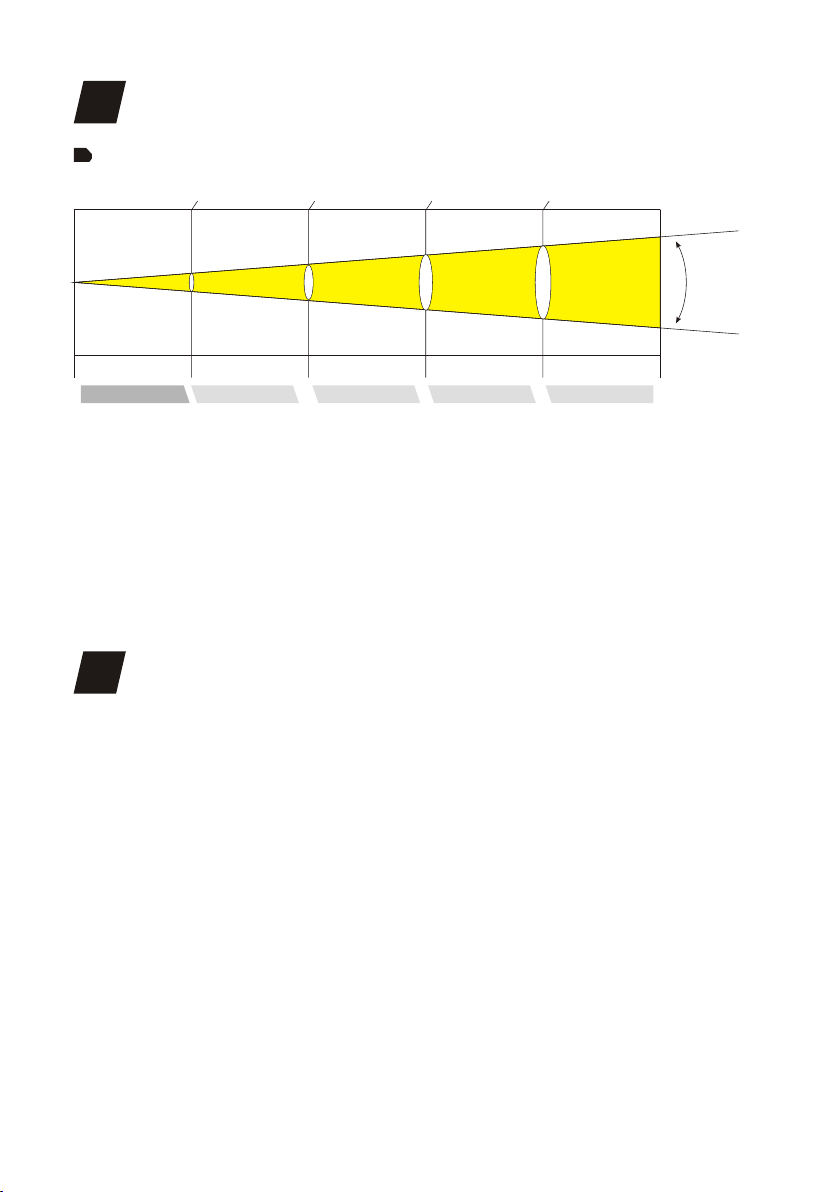
• 13°Beam angle
• Specific high precision glass optic system
• 1 Rotating gobo wheel with 6 rotatable and interchangeable gobos plus open (3 glass gobos and 3
metal
gobos with speed adjustable, stream effect, dithering effect and rotatable clockwise or anticlockwise
• Gobo indexing available
• Gobo size 22.9mm (external dimensions)/16mm (inner dimensions)
• 1 Static gobo wheel with 8 gobos plus open
• Gobo overlay (gobo morphing)
• 1 Color wheel with 7 colors plus open (available for half color mode)
• Variable direction rainbow effect with speed adjustable
• Gobo time and color time controllable
• 2.5M-15M electric focus
• An effect wheel with 3-facet prism/linear prism/frost filter (hybrid effect for wash)with variable speed
and direction
• 0-100% Smooth linear LED dimmer (2 dimmer modes)
• 25T/sec high speed LED shutter/strobe effect with variable speed
• Preset variable/random strobe and dimming pulse effect
• 13/15/17 DMX channels USITT DMX-512
• DMX512, master-slave, and sound activated controllable or auto operation(7 built-in programs)
• DMX recorder and edit function integrated
• Sound control with sensitivity adjustment
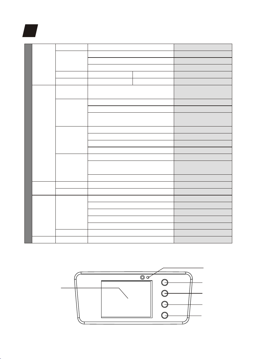
• 2.4" TFT LCD display (320*240pix) with 4 control buttons
• 180°Reversible for LCD display
• LCD display switch-off automatically after 60 seconds
• DMX signal monitoring indicator available
• Lower noise and efficient FAN cooling system
• Efficient low noise self adjusting fan cooling system
• Constant temperature readout and management function
• Over heat protection management
• Powercon IN/ OUT with power switch and fuse
• 3-Pin DMX connectors IN/OUT
• DB rating@1M=54.18dB
• IP20 protection rating
• -35℃ to 45℃ ambient temperature
• 2*1/4 turn fastening Omega Clamps (Adaptable vertically and horizontally)
• 1*Safety attachment point
• CE (EMC/LVD) and RoHS certified
.03.

Specifications
Input Voltage:
LED Quantities:
Control Signal:
Control Channel:
Power Consumption:
Dimensions:
Packing Dimensions:
Net Weight:
Gross Weight:
AC90-260V 50/60Hz
:1*250W 7500K white LED
DMX512, master-slave and sound activated or auto operation
13/15/17 DMX channels USITT DMX-512
290W
199(D)*348(W)*462(H)mm
375(D)*370(W)*525(H)mm
12.4kg
15kg
Static gobosRotating gobos Colors
Red Cyan Green
Yellow Magenta Blue
Orange
.04.

PHOTOMETRIC DATA
4
OPERATION INSTRUCTIONS
5
· The is for beam effect for on-site decoration purpose.
· Don’t turn on the fixture if it’s been through severe temperature difference like after
transportation because it might damage the light due to the environment changes.
So make sure to operate the fixture until it is in normal temperature.
· This light should be keep away from strong shaking during any transportation or
movement.
· Don’t pull up the light by only the head, or it might cause damages to the
mechanical parts.
· Don’t expose the fixture in overheat, moisture or environment with too much dust
when installing it. And don’t lay any power cables on the floor. Or it might cause
electronic shock to the people.
· Make sure the installation place is in good safety condition before installing the
fixture.
· Make sure to put the safety chain and check whether the screws are screwed
properly when installing the fixture.
· Make sure the lens are in good condition. It’s recommended to replace the units if
MINISPOT 250
ø 0.52 / ø 1.70 ø 1.03 / ø 3.38 ø 2.06 / ø 6.75
Beam Diameter (m/ft)ø 1.53 / ø 5.01
13.2°Beam Angle LUX 0.0929=FC×
Photometric Beam Angle Data
0m
2302 / 24790
13°
2.5m(8.2ft) 5m(16.4ft) 7.5m(24.6ft) 10m(32.8ft)
( FC/LUX )
573 / 6170 280 / 3020 177 / 1980
.05.

MENU OPERATIONS
8
MIC
LCD DISPLAY
Menu
Up
Enter
Down
MENU
A001-AXXX
CH15
Ch13
CH17
Internal Program 1~8 Master/Alone
Yes/No
Wire DMX
Wireless DMX
Act WDMX & Out
Reverse Pan (On/Off)
Reverse Tilt (On/Off)
Select Pan 630°/540° /360°
Select Tilt 270°/180°/90°
Mic sensitivity 0~99%
OFF Signal Mode (On/Off)
Half Color Wheel(On/Off)
XXX℃/℉
V1.1~v9.9
Total Reset
Pan/Tilt Reset
Color Reset
Gobo Reset
The Others Reset
PAN=XXX......
PAN=XXX......
Dmx Address
Channel Mode
Auto Run
Music Control
Reset Default
Temperature
Software Version
Reset
Channel
Calibration
Signal Set
Pan/Tilt
UI SET
MENU
Option
Information
Manual
Control
ADVANCED
(Acc ess C ode 0 88)
Function
Mode
DMX address setting
Standard channel
Vector channel
Extend channel
Alone Mode
Sound Mode
Overloading factory all
parameters
Wire DMX Input
Wireless DMX Input
Wireless DMX input, Wire DMX
output signal at the same time
Pan scan reverse
Tilt scan reverse
Pan angle select
Tilt angle select
Mic sensitivity Setting
No DMX signal,Keep the original
State(No)Reset state
Start half the color function
Current temperature
Software version
Reset all
Pan/Tilt reset
Color Reset
Gobo Reset
Other Reset
Channel value control
Calibration Function
.06.

Connect the provided XLR cable to the female 3-pin XLR output of your controller and
the other side to the male 3-pin XLR input of the moving head. You can chain multiple
Moving head together through serial linking. The cable needed should be two core,
screened cable with XLR input and output connectors. Please refer to the diagram
below.
DMX-512 connection with DMX terminator
DMX-512 CONTROL CONNECTIONS
7
DMX Output
3-Pin XLR Socket
DMX Input
3-Pin XLR Socket
1:Ground
2:Data(-)
3:Data(+)
1 2
3
12
3
1
2
3
1
2
3
COMMON
DMX+
DMX-
DMX512 IN
3-PIN XLR
DMX512 OUT
3-PIN XLR
For installations where the DMX cable has to run a long
distance or is in an electrically noisy environment, such as in a
discotheque, it is recommended to use a DMX terminator. This
helps in preventing corruption of the digital control signal by
electrical noise. The DMX terminator is simply an XLR plug
with a 120 Ω resistor connected between pins 2 and 3,which is
then plugged into the output XLR socket of the last fixture in
the chain. Please see illustrations below.
12
3
PIN3
PIN2
120 Ω
DMX IN
DMX OUT
POWER IN
POWER OUT
Fuse
Power Switch
DMX IN
POWER IN
.07.

.08.
Clamp Mounting:
assembly that integrates the bottom of the base, the included “Omega Bracket,” and
the safety cable rigging point in one unit (see the illustration below). When mounting
this fixture to truss be sure to secure an appropriately rated clamp to the included
omega bracket using a M10 screw fitted through the center hole of the “omega
bracket”. As an added safety measure be sure to attached at least one properly rated
safety cable to the fixture using on of the safety cable rigging point integrated in the
base assembly.
Regardless of the rigging option you choose for your , always be sure to
secure your fixture with a safety cable. The fixture provides a built-in rigging point for
a safety cable on the hanging bracket as illustrated above. Be sure to only use the
designated rigging point for the safety cable and never secure a safety cable to a
carrying handle.
The provides two unique mounting bracket MINISPOT 250
MINISPOT 250
②
① Omega Bracket
② Satety Clamp
③ Safety Cable
④ 1/4 Turn Quick-Lock Fasteners
①
③
④
1/4 Turn 1/4 Turn

there are any damages or severe scratch.
· Make sure the fixture is operated by qualified personnel who knows the fixture
before using.
· Keep the original packages if any second shipment is needed.
· Don’t try to change the fixtures without any instruction by the manufacturer or the
appointed repairing agencies.
· It is not in warranty range if there are any malfunctions from not following the user
manual to operate or any illegal operation, like shock short circuit, electronic shock,
lamp broke, etc.
Cautions: For added protection mount the fixtures in areas outside walking paths,
seating areas, or in areas were the fixture might be reached by unauthorized
personnel.
Before mounting the fixture to any surface, make sure that the installation area can
hold a minimum point load of 10 times the device’s weight.
Fixture installation must always be secured with a secondary safety attachment, such
as an appropriate safety cable.
Never stand directly below the device when mounting, removing, or servicing the
fixture.
from a ceiling, or set on a flat level surface (see illustration below). Be sure this fixture
is kept at least 0.5m (1.5 ft) away from any flammable materials (decoration etc.).
Always use and install the supplied safety cable as a safety measure to prevent
accidental damage and/or injury in the event the clamp fails.
Mounting points: Overhead mounting requires extensive experience, including
amongst others calculating working load limits, a fine knowledge of the installation
material being used, and periodic safety inspection of all installation material and the
fixture. If you lack these qualifications, do not attempt the installation yourself.
Improper installation can result in bodily injury.
Be sure to complete all rigging and installation procedures before connecting the
main power cord to the appropriate wall outlet.
INSTALLATIONS
6
.09.

DMX CHANNELS
9
0-255
0-255
0-255
0-255
0-15
16-31
32-47
48-63
64-79
80-95
96-111
112-127
128-189
190-193
194-255
0-7
8-15
16-23
24-31
32-39
40-47
48-55
56-63
64-71
72-79
80-87
88-95
96-103
104-111
112-119
120-127
128-189
190-193
194-255
0-9
10-19
20-29
30-39
PAN Movement
Fine control of Pan movement
Tilt Movement
Fine control of Tilt movement
Open / white
Color 1
Color 2
Color 3
Color 4
Color 5
Color 6
Color 7
Forwards rainbow effect from fast to slow
Color rotation stop
Backwards rainbow effect from slow to fast
Open
White+Color 1
/ white
Color 1
Color 1+Color 2
Color 2
Color 2+Color 3
Color 3
Color 3+Color 4
Color 4
Color 4+Color 5
Color 5
Color 5+Color 6
Color 6
Color 6+Color 7
Color 7
Color 7+White
Forward rainbow effect from fast to slow
Color rotation stop
Backward rainbow effect from slow to fast
Open
Gobo 1
Gobo 2
Gobo 3
Mode/Channel Function Values Description
EX
1
2
3
4
5
5
6
8b
1
2
3
3
4
16b
1
2
3
4
5
5
6
Pan
Pan-fine
Tilt
Tile-fine
Color
wheel1
Color
wheel
(Mode 2)
Gobo1
Wheel
.10.

40-49
50-59
60-69
70-89
90-109
110-129
130-149
150-169
170-189
190-255
0-127
128-189
190-193
194-255
0-31
32-63
64-95
96-127
128-159
160-191
192-223
224-255
0-255
0-255
0-9
10-19
20-29
30-39
40-49
50-59
60-69
70-79
80-89
90-101
102-113
114-125
126-137
138-149
150-161
162-173
174-185
186-255
0-63
Gobo 4
Gobo 5
Gobo 6
Gobo 1 shake slow to fast
Gobo 2 shake slow to fast
Gobo 3 shake slow to fast
Gobo 4 shake slow to fast
Gobo 5 shake slow to fast
Gobo 6 shake slow to fast
Rot.gobo wheel cont.rotation slow to fast
Gobo indexing
Forwards gobo rotation from fast to slow
Gobo rotation stop
Backwards rainbow effect from slow to fast
Hole with spot
Gobo 1
Gobo 2
Gobo 3
Gobo 4
Gobo 5
Gobo 6
Gobo 7
Gobo 8
Gobo 1 shake slow to fast
Gobo 2 shake slow to fast
Gobo 3 shake slow to fast
Gobo 4 shake slow to fast
Gobo 5 shake slow to fast
Gobo 6 shake slow to fast
Gobo 7 shake slow to fast
Gobo 8 shake slow to fast
Gobo wheel rotation from slow to fast
Shutter closed
Shutter open
Strobe effect slow to fast
Shutter open
Pulse-effect in sequences slow to fast
Shutter open
Random strobe effect slow to fast
Shutter open
Dimmer0%...100%
In(near)to out(far)
OFF
7
8
9
10
11
Gobo1
rotation
Gobo
wheel 2
Shutter
Dimmer
Focus
5
6
7
8
9
7
8
9
10
11
.11.

64-127
128-191
192-255
0-63
64-127
128-191
192-255
0-225
226-235
236-245
246-255
0-79
80-84
85-87
88-90
91-93
94-96
97-99
100-119
120-139
140-159
160-179
180-199
200-219
220-239
240-255
0-255
0-255
3 Facet prism
5 Facet prism
Frost
Prism rotation stop
Forwards rotation from fast to slow
Prism rotation stop
Backwards rotation from slow to fast
Max to min speed
Blackout by movement
Blackout by all wheel changing
No function
No function
All motor reset
Scan motor reset
Colors motor reset
Gobo motor reset
Shutter&Dimmer motor reset
Other motor reset
Internal program 1
Internal program 2
Internal program 3
Internal program 4
Internal program 5
Internal program 6
Internal program 7
Internal sound program 1
Max to min speed
Max to min speed
12
13
14
15
16
17
Prism&
Frost
Rotation
prism
Speed
PAN/Tilt
Special
function
Color Time
Gobo Time
10
11
12
13
12
13
14
15
.12.

The following points have to be considered during the inspection:
1) All screws for installing the devices or parts of the device have to be tightly
connected and must not be corroded.
2) There must not be any deformations on the housing, color lenses, fixations and
installation spots (ceiling, suspension, trussing).
3) Mechanically moved parts must not show any traces of wearing and must not
rotate with unbalances.
4) The electric power supply cables must not show any damage, material fatigue or
sediments.
Further instructions depending on the installation spot and usage have to be
adhered by a skilled installer and any safety problems have to be removed.
In order to make the lights in good condition and extend the life time, we suggest a
regular cleaning to the lights.
1) Clean the inside and outside lens each week to avoid the weakneness of the lights
due to accumulation of dust.
2) Clean the fan each week.
3) A detailed electric check by approved electrical engineer each three month, make
sure that the circuit contacts are in good condition, prevent the poor contact of
circuit from overheating.
We recommend a frequent cleaning of the device. Please use a moist, lint- free cloth.
Never use alcohol or solvents.
There are no serviceable parts inside the device. Please refer to the instructions
under “Installation instructions”.
Should you need any spare parts, please order genuine parts from your local dealer.
MAINTENANCE AND CLEANING
10
Disconnect from mains before starting maintenance operation.
CAUTION
.13.

.14.

ADD 3rd Floor, No. 288, Guangzhu East Line, Pingwen, Lanhe Town,Nansha District,
Guangzhou, China
Tel. +86 20 8499 2310/2320/2330
Fax +86 20 8499 2360
E-mail info@color-imagination.com
Website www.color-imagination.com
www.facebook.com/color.imagination.1
www.youtube.com/user/colorimaginationj
twitter.com/colorimaginej
Follow
us on
This manual suits for next models
1
Table of contents
Other Color imagination Lighting Equipment manuals

Color imagination
Color imagination SI-071 User manual

Color imagination
Color imagination SI-056 User manual

Color imagination
Color imagination SI-017 User manual

Color imagination
Color imagination SI-055 User manual

Color imagination
Color imagination MINISPOT 250Z User manual

Color imagination
Color imagination ProFollow 330 User manual

Color imagination
Color imagination LED-PAR36X3W-UV SI-027 User manual

Color imagination
Color imagination LEDZOOM 1915F User manual