Color imagination LEDZOOM 1915F User manual

User Manual
KEEP THIS MANUAL FOR FUTURE NEEDS
tc150°C
LED 0.2m ta40°C
SI-064
ADD 3rd Floor, No. 288, Guangzhu East Line, Pingwen, Lanhe Town,
Nansha District,Guangzhou, China
Tel. +86 20 8499 2310/2320/2330
Fax +86 20 8499 2360
E-mail info@color-imagination.com
Website www.color-imagination.com
www.facebook.com/color.imagination.1
www.youtube.com/user/colorimaginationj
twitter.com/colorimaginej
Follow
us on
LEDZOOM
1915F

.01.
If the device has been exposed to temperature changes due to environmental changes,
do not switch it on immediately. The arising condensation could damage the device.
Leave the device switched off until it has reached room temperature.
This device falls under protection-class I. Therefore it is essential that the device be
earthed.
The electric connection must carry out by qualified person.
The device shall only be used with rate voltage and frequency.
Make sure that the available voltage is not higher than stated at the end of this manual.
Make sure the power cord is never crimped or damaged by sharp edges. If this would
be the case, replacement of the cable must be done by an authorized dealer.
Always disconnect from the mains, when the device is not in use or before cleaning it.
Only handle the power cord by the plug. Never pull out the plug by tugging the power
cord.
During initial start-up some smoke or smell may arise. This is a normal process and
does not necessarily mean that the device is defective, it should decrease gradually.
Please don't project the beam onto combustible substances.
Fixtures cannot be installed on combustible substances, keep more than 50cm
distance with wall for smooth air flow, so there should be no shelter for fans and
ventilation for heat radiation.
If the external flexible cable or cord of this luminaire is damaged, it shall be exclusively
replaced by the manufacturer or his service agent or a similar qualified person in order
to avoid a hazard.
This device has left the factory in perfect condition. In order to maintain this
condition and to ensure a safe operation, it is absolutely necessary for the user to
follow the safety instructions and warning notes written in this user manual.
C AU T I O N
Becareful with your operations.With a dangerous voltage you cansuffer a
dangerous electric shock when touching wires!
IMPORTANT
Damages caused by the disregard of this user manual are not subject to warranty.
The dealer will not accept liability for any resulting defects or problems.
SAFETY INSTRUCTIONS
1
Thank you for choosing our LEDZOOM 1915F. For your own safety, please read this
manual before installing the device. This manual covers the important information
on installation and applications. Please install and operate the fixture with following
instructions. Meanwhile, please keep this manual well for future needs.
The LEDZOOM 1915F is made of a new type of high temperature strength of
engineering plastics and cast aluminum casing with nice outlook. The fixture is
designed and manufactured strictly following CE standards, complying with
international standard DMX512 protocol. It’s available independently controlled
and linkable with each other for operation. And it is applicable for large-scale live
performances, theater, studio, nightclubs and discos.
The LEDZOOM 1915F adopts 19PCS 4-IN-1 15W LEDs (USA LED) which features high
brightness and stability. Please carefully unpack it when you receive the fixture and
check whether it is damaged during the transportation. And please check whether
the following items are included inside the box:
.02.
UNPACKING
2
①
Moving Head
Signal Cable
Power Cable
Power Out
Omega Clamp
Safety Cable
User Manual
1PC
1PC
1PC
1PC
1PC
1PC
1PC
①
②
③
④
⑤
⑥
⑦
④
⑤
⑥ ⑦
②
③
Euro Standard UK Standard
USA Standard
OPTIONAL

400
310185
203
375
.04.
PHOTOMETRIC DATA
4
8°~50°Beam Angle LUX 0.0929=FC×
Photometric Beam Angle Data
2900 / 31200 415/ 4470 96 / 1030
(FC/LUX)
8°50°
672 / 7230 81 / 870
2074 / 22320 381 / 4105 71 / 760
544 / 5860 62 / 675
3358 / 36150
3980 / 42840
614 / 6615
674 / 7250
108 / 1165
122 / 1310
877 / 9435
964 / 10380
104 / 1120
108 / 1160
10033 / 108000 1741 / 18740 329 / 3540
2653 / 28560 282 / 3035
R
G
B
W
RGBW
1m (3.3ft) 3m (9.8ft) 5m (16.4ft)0m (0ft) 7m (23.0ft)
190 / 2045
27 / 290
137 / 1480
20 / 220
224 / 2415
236 / 2540
37 / 400
36 / 390
641 / 6900
104 / 1120
14 / 150
11 / 120
19 / 200
19 / 200
51 / 550
.03.
Specifications
Input Voltage:
LED Quantities:
Control Signal:
Control Channel:
Power Consumption:
Dimensions:
Packing Dimensions:
Net Weight:
Gross Weight:
Features
AC90-260V 50/60Hz
19*15W USA 4-IN-1 LEDs
DMX512, master-slave and sound activated or auto operation
12/22 DMX Channels
295W
185(D)*310(W)*400(H)mm
356(D)*290(W)*430(H)mm
7.8kg
9.3kg
FEATURES & SPECIFICATIONS
3
• 19PCS 15W 4-IN-1 LEDs (USA LED)
• LEDs in 3 sections and each section controllable individually
• Specific optic system of highly efficient elements
• Motorized zoom 8° -50°
• High light output with 3990LUX(8°) and 483LUX(50°) @7M at full RGBW
• 50,000 hours lifespan and low power consumption
• Amazing RGBW color mixing
• High efficiency LED shutter with variable speed
• Smooth LED dimmer
• LED rainbow effect
• 10 built-in default programs with Macros effect
• Strobe effect with 1-25 flashes per second
• Random strobe effect and pulse strobe effect
• General dimming and blackout for all four colors
• 3 DMX channel modes, 12CH/22CH/22CH (designed mode)
• DMX512, master-slave and sound activated controllable or auto operation
• Blue LCD display
• Lower noise and efficient FAN cooling system
• Powercon IN/ OUT
• 45°C max ambient temperature
• IP20 protection rating
• 55dB at 3’ dB rating
• 3-pin DMX connectors IN/OUT
320
98
159
175

· The moving head is for beam effect for on-site decoration purpose.
· Don’t turn on the fixture if it’s been through severe temperature difference like
after transportation because it might damage the light due to the environment
changes. So make sure to operate the fixture until it is in normal temperature.
· This light should be keep away from strong shaking during any transportation or
movement.
· Don’t pull up the light by only the head, or it might cause damages to the
mechanical parts.
· Don’t expose the fixture in overheat, moisture or environment with too much dust
when installing it. And don’t lay any power cables on the floor. Or it might cause
electronic shock to the people.
· Make sure the installation place is in good safety condition before installing the
fixture.
· Make sure to put the safety chain and check whether the screws are screwed
properly when installing the fixture.
· Make sure the lens are in good condition. It’s recommended to replace the units if
there are any damages or severe scratch.
· Make sure the fixture is operated by qualified personnel who knows the fixture
before using.
· Keep the original packages if any second shipment is needed.
· Don’t try to change the fixtures without any instruction by the manufacturer or
the appointed repairing agencies.
· It is not in warranty range if there are any malfunctions from not following the
user manual to operate or any illegal operation, like shock short circuit, electronic
shock, lamp broke, etc.
Never stand directly below the device when mounting, removing, or servicing the
fixture.
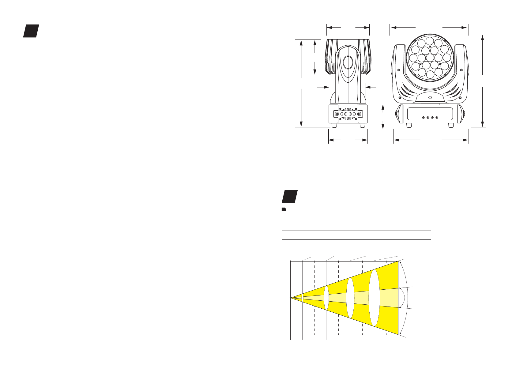
from a ceiling, or set on a flat level surface (see illustration below). Be sure this fixture
is kept at least 0.5m (1.5 ft) away from any flammable materials (decoration etc.).
Always use and install the supplied safety cable as a safety measure to prevent
accidental damage and/or injury in the event the clamp fails.
Mounting points: Overhead mounting requires extensive experience, including
amongst others calculating working load limits, a fine knowledge of the installation
material being used, and periodic safety inspection of all installation material and the
fixture. If you lack these qualifications, do not attempt the installation yourself.
Improper installation can result in bodily injury.
Be sure to complete all rigging and installation procedures before connecting the
main power cord to the appropriate wall outlet.
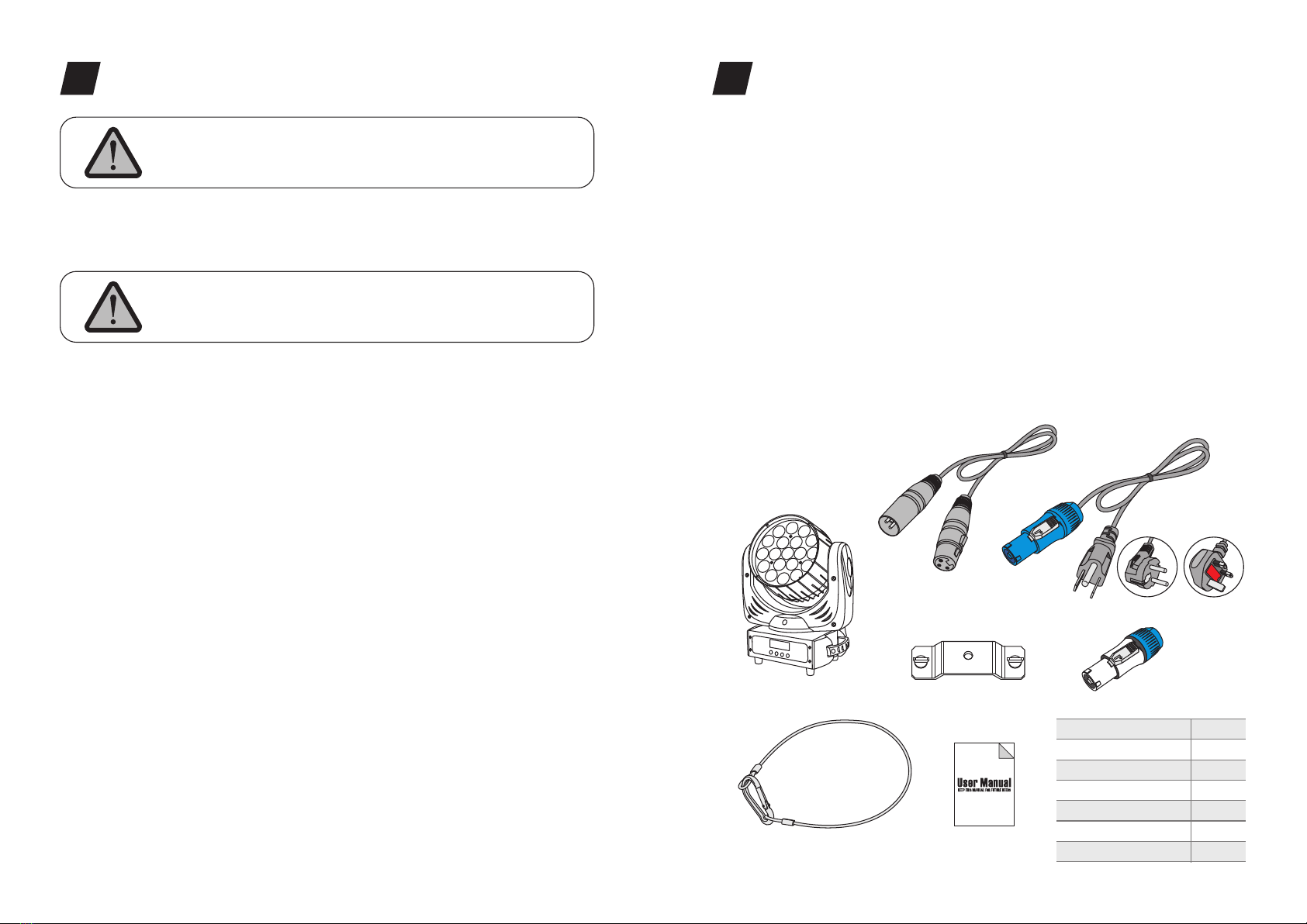
Clamp Mounting: The LEDZOOM 1915F provides a unique mounting bracket
assembly that integrates the bottom of the base, and the safety cable rigging point in
one unit (see the illustration below). When mounting this fixture to truss be sure to
secure an appropriately rated clamp to the included omega bracket using a M10
screw fitted through the center hole of the “omega bracket”. As an added safety
measure be sure to attached at least one properly rated safety cable to the fixture
using on of the safety cable rigging point integrated in the base assembly.
.05.
OPERATION INSTRUCTIONS
5
Cautions: For added protection mount the fixtures in areas outside walking paths,
seating areas, or in areas were the fixture might be reached by unauthorized
personnel.
Before mounting the fixture to any surface, make sure that the installation area can
hold a minimum point load of 10 times the device’s weight.
Fixture installation must always be secured with a secondary safety attachment, such
as an appropriate safety cable.
INSTALLATIONS
6
.06.
①
②
③
④
① Omega Bracket
② Satety Clamp
③ Safety Cable
④ 1/4 Turn Quick-Lock Fasteners
Turn around Turn around

POWER IN
DMX IN
.07.
DMX Output
3-Pin XLR Socket
DMX Input
3-Pin XLR Socket
1:Ground
2:Data(-)
3:Data(+)
1 2
3
12
3
1
2
3
1
2
3
COMMON
DMX+
DMX-
DMX512 IN
3-PIN XLR
DMX512 OUT
3-PIN XLR
2 1
Regardless of the rigging option you choose for your , always be
sure to secure your fixture with a safety cable. The fixture provides a built-in rigging
point for a safety cable on the hanging bracket as illustrated above. Be sure to only
use the designated rigging point for the safety cable and never secure a safety cable
to a carrying handle.
LEDZOOM 1915F
Connect the provided XLR cable to the female 3-pin XLR output of your controller and
the other side to the male 3-pin XLR input of the moving head. You can chain multiple
Moving head together through serial linking. The cable needed should be two core,
screened cable with XLR input and output connectors. Please refer to the diagram
below.
DMX-512 connection with DMX terminator
DMX-512 CONTROL CONNECTIONS
7
Fuse
POWER IN
POWER OUT
DMX IN
DMX OUT
.08.
For installations where the DMX cable has to run a long
distance or is in an electrically noisy environment, such as
in a discotheque, it is recommended to use a DMX
terminator. This helps in preventing corruption of the
digital control signal by electrical noise. The DMX
terminator is simply an XLR plug with a 120 Ω resistor
connected between pins 2 and 3,which is then plugged
into the output XLR socket of the last fixture in the chain.
Please see illustrations below.
12
3
PIN3
PIN2
120 Ω
MENU OPERATIONS
8
DMX Address
Setting
DMX Address:
001 512
Work mode
Setting
Work mode:
DMX512 Slave Sound SlowFast
Invert PAN PAN Reversal
Yes? No?
Invert Invert TILT TILT Reversal
Yes? No?
Design Mode set PAN
001 024
PANMICO
001 024
TILT
001 024
TILTMICO
001 024
SPEED
001 024
DIM_R0
001 024
DIM_R1
001 024
DIM_R2
001 024
Light effect
001 024
FOCUS
001 024
DIM_G0
001 024
DIM_G1
001 024
DIM_G2
001 024
Light Speed
001 024
DIM
001 024
DIM_B0
001 024
DIM_B1
001 024
DIM_B2
001 024
MACRO_CH
001 024
STROBE
001 024
DIM_W0
001 024
DIM_W1
001 024
DIM_W2
001 024
RESET_CH
001 024
Display set Backlight on
Yes? No?
Chanel Mode set Channel model:
12 Channels Design Mode22 Channels
Restore Factory Load Default
Yes?
Reset Reset All
Yes?

.10.
.09.
DMX CHANNELS
9
0-255
0-255
0-255
0-255
0-255
0-255
0-255
0-003
004-095
096-176
177-255
0-255
0-255
0-255
0-255
0-255
0-255
0-255
0-255
0-255
0-255
0-255
0-255
0-255
0-255
0-255
0-255
0-024
025-049
050-074
075-099
100-124
125-149
150-174
175-179
200-224
225-255
0-255
PAN Movement, 0-540°
Fine control of Pan movement
Tilt Movement, 0-270°
Fine control of Tilt movement
Speed control of PAN/TILT movement
0-100% Linear zoom from 8°-50°
0-100% Linear dimmer from dark to bright
No function
Strobe effect from slow to fast, 1-25Hz
Random strobe effect
Pulse strobe effect
0-100% Red dimmer from dark to bright
0-100% Green dimmer from dark to bright
0-100% Blue dimmer from dark to bright
0-100% White dimmer from dark to bright
0-100% Red 1 dimmer from dark to bright
0-100% Green 1 dimmer from dark to bright
0-100% Blue 1 dimmer from dark to bright
0-100% White 1 dimmer from dark to bright
0-100% Red 2 dimmer from dark to bright
0-100% Green 2 dimmer from dark to bright
0-100% Blue 2 dimmer from dark to bright
0-100% White 2 dimmer from dark to bright
0-100% Red 3 dimmer from dark to bright
0-100% Green 3 dimmer from dark to bright
0-100% Blue 3 dimmer from dark to bright
0-100% White 3 dimmer from dark to bright
Built-in programs1
Built-in programs2
Built-in programs3
Built-in programs4
Built-in programs5
Built-in programs6
Built-in programs7
Built-in programs8
Built-in programs9
Built-in programs10
Speed control of built-in programs from fast to slow
Mode/Channel Function Values Description
DE
1
2
3
4
5
6
7
8
9
10
11
12
13
14
15
16
17
18
19
20
21
22
8B
1
2
3
4
5
6
7
8
9
10
11
12
16B
1
2
3
4
5
6
7
8
9
10
11
12
13
14
15
16
17
18
19
20
21
22
Pan
Pan Fine
Tilt
Tilt Fine
Speed
Zoom
Dimmer
Strobe
Red
Green
Blue
White
Red 1
Green 1
Blue 1
White
Red 2
Green 2
Blue 2
White 2
Red 3
Green 3
Blue 3
White 3
Built-in
Program
Speed
0-049
050-099
100-149
150-199
200-255
0-099
100-250
251-255
CH1-CH12 activated
Running built-in programs
Auto 1
Auto 2
Sound control
No function
No function
Reset in 3 seconds
23
24
13
14
23
24
Macro
Reset
The following points have to be considered during the inspection:
1) All screws for installing the devices or parts of the device have to be tightly connected
and must not be corroded.
2) There must not be any deformations on the housing, color lenses, fixations and
installation spots (ceiling, suspension, trussing).
3) Mechanically moved parts must not show any traces of wearing and must not rotate with
unbalances.
4) The electric power supply cables must not show any damage, material fatigue or sediments.
Further instructions depending on the installation spot and usage have to be adhered by a
skilled installer and any safety problems have to be removed.
In order to make the lights in good condition and extend the life time, we suggest a regular
cleaning to the lights.
1) Clean the inside and outside lens each week to avoid the weakneness of the lights due to
accumulation of dust.
2) Clean the fan each week.
3) A detailed electric check by approved electrical engineer each three month, make sure
that the circuit contacts are in good condition, prevent the poor contact of circuit from
overheating.
We recommend a frequent cleaning of the device. Please use a moist, lint- free cloth. Never
use alcohol or solvents.
There are no serviceable parts inside the device. Please refer to the instructions under
“Installation instructions”.
Should you need any spare parts, please order genuine parts from your local dealer.
MAINTENANCE AND CLEANING
10
Disconnect from mains before starting maintenance operation.
C AU T I O N
This manual suits for next models
1
Table of contents
Other Color imagination Lighting Equipment manuals

Color imagination
Color imagination SI-071 User manual

Color imagination
Color imagination ProFollow 330 User manual

Color imagination
Color imagination SI-056 User manual

Color imagination
Color imagination MINISPOT 250 User manual

Color imagination
Color imagination SI-055 User manual

Color imagination
Color imagination LED-PAR36X3W-UV SI-027 User manual

Color imagination
Color imagination SI-017 User manual

Color imagination
Color imagination MINISPOT 250Z User manual