Color imagination SI-071 User manual

User Manual
KEEP THIS MANUAL FOR FUTURE NEEDS
SI-071
ADD 3rd Floor, No. 288, Guangzhu East Line, Pingwen, Lanhe Town,
Nansha District,Guangzhou, China
Tel. +86 20 8499 2310/2320/2330
Fax +86 20 8499 2360
E-mail info@color-imagination.com
Website www.color-imagination.com
www.facebook.com/color.imagination.1
www.youtube.com/user/colorimaginationj
twitter.com/colorimaginej
Follow
us on
tc150°C
LED 0.2m ta40°C
LEDSPOT
300

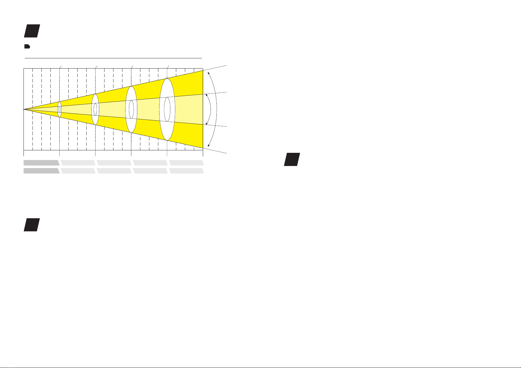
Thank you for choosing our LEDSPOT 300 with linear motorized zoom from 12° to
36°. For your own safety, please read this manual before installing the device. This
manual covers the important information on installation and applications. Please
install and operate the fixture with following instructions. Meanwhile, please keep
this manual well for future needs.
The LEDSPOT 300 is made of a new type of high temperature strength of engineering
plastics and cast aluminum casing with nice outlook. The fixture is designed and
manufactured strictly following CE standards, complying with international standard
DMX512 protocol. It’s available independently controlled and linkable with each
other for operation. And it is applicable for large-scale live performances, theater,
studio, nightclubs and discos.
The LEDSPOT 300 adopts powerful 300W pure white LED which features high
brightness and stability. Please carefully unpack it when you receive the fixture and
check whether it is damaged during the transportation. And please check whether
the following items are included inside the box:
LEDSPOT 300
Signal Cable
Power Cable
Power Out
Omega Clamp
Safety Cable
User Manual
1PC
1PC
1PC
1PC
2PC
1PC
1PC
①
②
③
④
⑤
⑥
⑦
①
②
④
⑤
⑥ ⑦
.01. .02.
③
Euro Standard UK Standard
USA Standard
OPTIONAL
If the device has been exposed to temperature changes due to environmental changes,
do not switch it on immediately. The arising condensation could damage the device.
Leave the device switched off until it has reached room temperature.
This device falls under protection-class I. Therefore it is essential that the device be
earthed.
The electric connection must carry out by qualified person.
The device shall only be used with rate voltage and frequency.
Make sure that the available voltage is not higher than stated at the end of this manual.
Make sure the power cord is never crimped or damaged by sharp edges. If this would
be the case, replacement of the cable must be done by an authorized dealer.
Always disconnect from the mains, when the device is not in use or before cleaning it.
Only handle the power cord by the plug. Never pull out the plug by tugging the power
cord.
During initial start-up some smoke or smell may arise. This is a normal process and
does not necessarily mean that the device is defective, it should decrease gradually.
Please don't project the beam onto combustible substances.
Fixtures cannot be installed on combustible substances, keep more than 50cm
distance with wall for smooth air flow, so there should be no shelter for fans and
ventilation for heat radiation.
If the external flexible cable or cord of this luminaire is damaged, it shall be exclusively
replaced by the manufacturer or his service agent or a similar qualified person in order
to avoid a hazard.
This device has left the factory in perfect condition. In order to maintain this
condition and to ensure a safe operation, it is absolutely necessary for the user to
follow the safety instructions and warning notes written in this user manual.
CAUTION
Becareful with your operations.With a dangerous voltage you cansuffer a
dangerous electric shock when touching wires!
IMPORTANT
Damages caused by the disregard of this user manual are not subject to warranty.
The dealer will not accept liability for any resulting defects or problems.
SAFETY INSTRUCTIONS
1UNPACKING
2

Specifications
Input Voltage:
LED Quantities:
Control Signal:
Control Channel:
Power Consumption:
Dimensions:
Packing Dimensions:
Net Weight:
Gross Weight:
AC90-260V 50/60Hz
1*300W white LED lamp
DMX512, master-slave and sound activated or auto operation
17/15/17 DMX channels USITT DMX-512
390W
318(D)*411(W)*628(H)mm
480(D)*610(W)*460(H)mm
21kg
23.5kg
Rotating gobos Static gobos Colors
UV
Features
• A 300W single white LED lamp
• 50000 hours life span and low power consumption
• 8/16 bit smooth and precise resolution for PAN/TILT movement
• 540°/630° PAN and 270° TILT movement
• Scan position memory, auto reposition after unexpected movement
• Linear motorized zoom with 12° to 36° beam angle
• Improved optics and flat beam field
• 1 rotatable gobo wheel with 7 rotatable and interchangeable glass gobos plus open
with speed adjustable, stream effect, dithering effect and rotatable clockwise or
anticlockwise
• Gobo indexing
• Gobo size 27.9mm (external dimensions)/23mm (inner dimensions)
• 1 static gobo wheel with 9 gobos plus open
• Gobo overlay (gobo morphing)
• 1 color wheel with 7 colors plus open
• Variable direction rainbow effect with speed adjustable
• 2 meter to infinite electric focus
• Motorized linear IRIS
• 3-facet prism with variable speed and direction
• Variable linear frost filter (Hybrid effect for wash)
• 0-100% linear LED dimmer
• 20T/sec high speed LED shutter/strobe effect with variable speed
• Preset variable/random strobe and dimming pulse effect
• 17/15/17 DMX channels USITT DMX-512
• Customizable DMX channel assignment (17CH)
• DMX512, master-slave, and sound activated controllable or auto operation
(8 built-in programs)
• DMX recorder and edit function integrated
• Blue background LCD display
• Powercon IN/OUT
• 3-pin XLR connectors IN/OUT
• Fan cooling system
• Constant temperature readout and management function
• 45℃ max ambient temperature
• IP20 protection rating
• 55dB at 3’dB rating
• 2*1/4 turn fastening Omega clamps
Red Green Pink
Blue Orange Yellow
.03. .04.
White
FEATURES & SPECIFICATIONS
3
411 318
628
495
231388
120

.05. .06.
1875 / 20180
418 / 4500
480 / 5250
105 / 1130
223 / 2400
48 / 510
126 / 1350
28 / 300
2.5m (8.2ft) 5m (16.4ft) 7.5m (24.6ft)0m (0ft)
(FC/LUX)
12°~36°Beam Angle LUX 0.0929=FC×
Photometric Beam Angle Data
12°36°
12°
36°
10m (32.8ft)
ø 0.55 / ø 1.83
Beam Diameter 12°
(m/ft)ø 1.04 / ø 3.46 ø 1.50 / ø 4.99 ø 2.06 / ø 6.86
ø 1.40 / ø 4.66 ø 2.70 / ø 8.99 ø 4.00 / ø 13.32 ø 5.30 / ø 17.65
Beam Diameter 36°
properly
· Make sure the lens are in good condition. It’s recommended to replace the units if
there are any damages or severe scratch.
· Make sure the fixture is operated by qualified personnel who knows the fixture
before using.
· Keep the original packages if any second shipment is needed.
· Don’t try to change the fixtures without any instruction by the manufacturer or
the appointed repairing agencies.
· It is not in warranty range if there are any malfunctions from not following the
user manual to operate or any illegal operation, like shock short circuit, electronic
shock, lamp broke, etc.
when installing the fixture.
PHOTOMETRIC DATA
4
OPERATION INSTRUCTIONS
5
· The LEDSPOT 300 is for spot effect for on-site decoration purpose.
· Don’t turn on the fixture if it’s been through severe temperature difference like
after transportation because it might damage the light due to the environment
changes. So make sure to operate the fixture until it is in normal temperature.
· This light should be keep away from strong shaking during any transportation or
movement.
· Don’t pull up the light by only the head, or it might cause damages to the
mechanical parts.
· Don’t expose the fixture in overheat, moisture or environment with too much dust
when installing it. And don’t lay any power cables on the floor. Or it might cause
electronic shock to the people.
· Make sure the installation place is in good safety condition before installing the
fixture.
· Make sure to put the safety chain and check whether the screws are screwed
Cautions: For added protection mount the fixtures in areas outside walking paths,
seating areas, or in areas were the fixture might be reached by unauthorized
personnel.
Before mounting the fixture to any surface, make sure that the installation area can
hold a minimum point load of 10 times the device’s weight.
Fixture installation must always be secured with a secondar y safety attachment, such
as an appropriate safety cable.
Never stand directly below the device when mounting, removing, or servicing the
fixture.
from a ceiling, or set on a flat level surface (see illustration below). Be sure this fixture
is kept at least 0.5m (1.5 ft) away from any flammable materials (decoration etc.).
Always use and install the supplied safety cable as a safety measure to prevent
accidental damage and/or injury in the event the clamp fails.
Mounting points: Overhead mounting requires extensive experience, including
amongst others calculating working load limits, a fine knowledge of the installation
material being used, and periodic safety inspection of all installation material and
the fixture. If you lack these qualifications, do not attempt the installation yourself.
Improper installation can result in bodily injury.
Be sure to complete all rigging and installation procedures before connecting the
INSTALLATIONS
6

.07. .08.
①
②
③
④
① Omega Bracket
② Satety Clamp
③ Safety Cable
④ 1/4 Turn Quick-Lock Fasteners
1/4 Turn 1/4 Turn
main power cord to the appropriate wall outlet.
Clamp Mounting: provides two unique mounting bracket
assembly that integrates the bottom of the base, the included “Omega Bracket,” and
the safety cable rigging point in one unit (see the illustration below). When mounting
this fixture to truss be sure to secure an appropriately rated clamp to the included
omega bracket using a M10 screw fitted through the center hole of the “omega
bracket”. As an added safety measure be sure to attached at least one properly rated
safety cable to the fixture using on of the safety cable rigging point integrated in the
base assembly.
Regardless of the rigging option you choose for your LEDSPOT 300, always be sure to
secure your fixture with a safety cable. The fixture provides a built-in rigging point
for a safety cable on the hanging bracket as illustrated above. Be sure to only use the
designated rigging point for the safety cable and never secure a safety cable to a
carrying handle.
The LEDSPOT 300
Connect the provided XLR cable to the female 3-pin XLR output of your controller
and the other side to the male 3-pin XLR input of the moving head. You can chain
multiple Moving head together through serial linking. The cable needed should be
two core, screened cable with XLR input and output connectors. Please refer to the
diagram below.
DMX-512 connection with DMX terminator
DMX-512 CONTROL CONNECTIONS
7
POWER IN
DMX IN
DMX IN
DMX OUT
POWER IN
POWER OUT
Fuse Power Switch
Importan t Notes:
1. Please do not link more than at AC220V voltage!
2. Please do not link more than 2PCS LEDSPOT 300 at AC110V voltage!
5PCS LEDSPOT 300
DMX Output
3-Pin XLR Socket
DMX Input
3-Pin XLR Socket
1:Ground
2:Data(-)
3:Data(+)
1 2
3
12
3
1
2
3
1
2
3
COMMON
DMX+
DMX-
DMX512 IN
3-PIN XLR
DMX512 OUT
3-PIN XLR

A001~AXXX
Auto Run
Music Control
On/Off
On/Off
On/Off
0~99%
Reset Default
Calibration
Temperature
Manual Control
Signal Set
Auto
Program1
..
Program8
Standard Mode
Basic Mode
Extended Mode
Master/Alone
Master/Alone
On/Off
Code(Code 088)
PAN, TILT, Color Wheel, Gobo
Wheel 1, Gobo Wheel 2,
Focus, Prism
XXX°C/°F
PAN=XXX……
Wire DMX
Wireless DMX
Act WDMX & Out
Steps(1...48)
Scenes 01
..
Scenes XX
:
Pan=XXX…
…
Time=xx.xS
DMX Address
Auto Play
Reset
Reverse Pan
Reverse Tilt
Mic sensitivity
Special
Edit Program
Mode of
channel
Sensitivity of mic
Set each scenes'
value and time
0-255
0-255
0-255
0-255
0-015
016-031
032-047
048-063
064-079
080-095
096-111
112-127
128-189
190-193
194-255
0-007
008-015
016-023
024-031
032-039
040-047
048-055
056-063
064-071
072-079
080-087
088-095
096-103
104-111
112-119
120-127
128-189
190-193
194-255
0-009
010-019
020-029
030-039
PAN Movement
Fine control of Pan movement
Tilt Movement
Fine control of Tilt movement
Open/White
Color 1
Color 2
Color 3
Color 4
Color 5
Color 6
Color 7
Forwards rainbow effect from fast to slow
Color rotation stop
Backwards rainbow effect from slow to fast
Open / White
White + Color 1
Color 1
Color 1 + Color 2
Color 2
Color 2 + Color 3
Color 3
Color 3 + Color 4
Color 4
Color 4 + Color 5
Color 5
Color 5 + Color 6
Color 6
Color 6 + Color 7
Color 7
Color 7 + White
Forwards rainbow effect from fast to slow
Color rotation stop
Backwards rainbow effect from slow to fast
Open
Gobo 1
Gobo 2
Gobo 3
Mode/Channel Function Values Description
DE
1
2
3
4
5
5
6
8B
1
2
3
3
4
16B
1
2
3
4
5
5
6
Pan
Pan Fine
Tilt
Tilt Fine
Color
(Mode 1)
Color
(Mode 2)
Gobo 1
MENU
.09. .10.
MENU OPERATIONS
8
For installations where the DMX cable has to run a long
distance or is in an electrically noisy environment, such as
in a discotheque, it is recommended to use a DMX
terminator. This helps in preventing corruption of the
digital control signal by electrical noise. The DMX
terminator is simply an XLR plug with a 120 Ω resistor
connected between pins 2 and 3,which is then plugged
into the output XLR socket of the last fixture in the chain.
Please see illustrations below.
12
3
PIN3
PIN2
120 Ω
Down
Enter
Up
Mode
MIC
LCD DISPLAY
DMX CHANNELS
9

040-049
050-059
060-069
070-079
080-099
100-119
120-139
140-159
160-179
180-199
200-219
220-255
0-127
128-189
190-193
194-255
0-009
010-019
020-029
030-039
040-049
050-059
060-069
070-079
080-089
090-099
100-111
112-123
124-135
136-147
148-159
160-171
172-183
184-195
196-207
208-255
0-031
032-063
064-095
096-127
128-159
160-191
192-223
Gobo 4
Gobo 5
Gobo 6
Gobo 7
Gobo 1 shake slow to fast
Gobo 2 shake slow to fast
Gobo 3 shake slow to fast
Gobo 4 shake slow to fast
Gobo 5 shake slow to fast
Gobo 6 shake slow to fast
Gobo 7 shake slow to fast
Rot. gobo wheel cont. rotation slow to fast
Gobo indexing
Forwards gobo rotation from fast to slow
Gobo rotation stop
Backwards gobo rotation from slow to fast
Open/white
Gobo 1
Gobo 2
Gobo 3
Gobo 4
Gobo 5
Gobo 6
Gobo 7
Gobo 8
Gobo 9
Gobo 1 shake slow to fast
Gobo 2 shake slow to fast
Gobo 3 shake slow to fast
Gobo 4 shake slow to fast
Gobo 5 shake slow to fast
Gobo 6 shake slow to fast
Gobo 7 shake slow to fast
Gobo 8 shake slow to fast
Gobo 9 shake slow to fast
Gobo wheel rotation from slow to fast
Shutter closed
shutter open
Strobe effect slow to fast
Shutter open
Pulse-effect in sequences
Shutter open
Random strobe effect slow to fast
7
5
7Gobo 1
Rot.
868 Gobo 2
979 Shutter
224-255
0-255
0-255
0-255
0-005
006-127
128-189
190-193
193-255
0-191
192-223
224-255
0-191
192-223
224-254
255
0-225
226-235
236-245
246-255
0-019
020-029
030-039
040-079
080-099
100-119
120-139
140-159
160-179
180-199
200-219
220-239
240-255
Shutter open
0-100% Linear dimmer
In(near) to out(far)
In(near, 12°) to out(far, 36°)
OFF
ON
Forwards rotation from fast to slow
Prism rotation stop
Backwards rotation from slow to fast
Max. diameter to Min.diameter
Pulse opening fast to slow
Pulse closing slow to fast
Frost 0~100%
Pulse opening fast to slow
Pulse closing slow to fast
Max. Frost
Max to min speed
Blackout by movement
Blackout by all wheel changing
No function
No function
No function
No function
No function
Motor reset
Internal program 1
Internal program 2
Internal program 3
Internal program 4
Internal program 5
Internal program 6
Internal program 7
Internal program 8
10
11
12
13
14
15
16
17
8
9
10
11
12
13
14
17
10
11
12
13
14
15
16
17
Dimmer
Focus
Zoom
Rotating
Prism
Iris
Frost
Speed of
Pan/Tilt
Special
.11. .12.

.13.
The following points have to be considered during the inspection:
1) All screws for installing the devices or parts of the device have to be tightly
connected and must not be corroded.
2) There must not be any deformations on the housing, color lenses, fixations and
installation spots (ceiling, suspension, trussing).
3) Mechanically moved parts must not show any traces of wearing and must not
rotate with unbalances.
4) The electric power supply cables must not show any damage, material fatigue or
sediments.
Further instructions depending on the installation spot and usage have to be
adhered by a skilled installer and any safety problems have to be removed.
In order to make the lights in good condition and extend the life time, we suggest a
regular cleaning to the lights.
1) Clean the inside and outside lens each week to avoid the weakneness of the lights
due to accumulation of dust.
2) Clean the fan each week.
3) A detailed electric check by approved electrical engineer each three month, make
sure that the circuit contacts are in good condition, prevent the poor contact of
circuit from overheating.
We recommend a frequent cleaning of the device. Please use a moist, lint- free cloth.
Never use alcohol or solvents.
There are no serviceable parts inside the device. Please refer to the instructions
under “Installation instructions”.
Should you need any spare parts, please order genuine parts from your local dealer.
MAINTENANCE AND CLEANING
10
Disconnect from mains before starting maintenance operation.
CAUTION
Table of contents
Other Color imagination Lighting Equipment manuals

Color imagination
Color imagination SI-017 User manual

Color imagination
Color imagination SI-056 User manual

Color imagination
Color imagination SI-055 User manual

Color imagination
Color imagination LEDZOOM 1915F User manual

Color imagination
Color imagination MINISPOT 250 User manual

Color imagination
Color imagination ProFollow 330 User manual

Color imagination
Color imagination MINISPOT 250Z User manual

Color imagination
Color imagination LED-PAR36X3W-UV SI-027 User manual