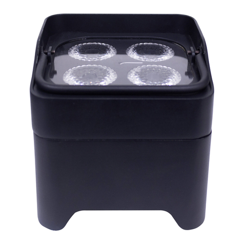
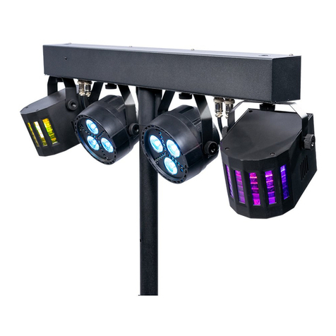
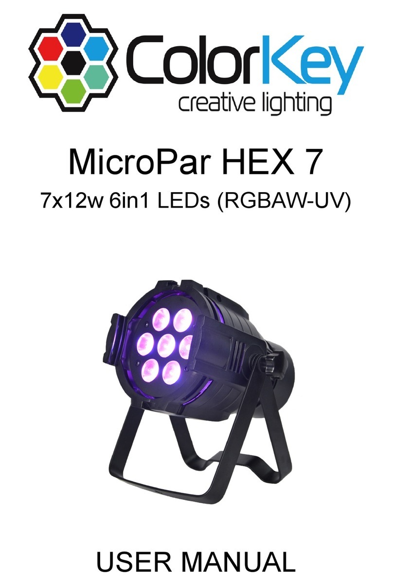
ColorKey MobilePar Hex 4 User manual

SPECIFICATIONS
Page 12
Input Voltage
Power Consumption
LEDs
Battery Spec
Charger Output voltage
LED Life Span
DMX Channels
Control Protocol
Control Mode
Signal Input&Output
Wireless
Function Effect
Refresh Rate
Beam Angle
Cooling Mode
Protection Grade
Anti-electricity Intension
Insulation Resistance
Dimensions
Weight
AC 100V - 260V,50-60Hz
55W
4 X 12 - watt R/G/B/A/W/UV 6in1 LEDs
50000 ~100000 hours
3,6,8,10 or 11CH
USITT DMX512
Standalone,Mater/slave, Auto,Sound Active
3 - pin XLR Male, 3 - pin XLR Female
2.4G,126 channels jumping frequency automatically
Dimmer, Strobe, Eotic, Gradual Change
1.5KHz
30°
Natural convection(no fan, no noise)
IP20
>1.5KV
>2MΩ
167 X 138 X 188 mm ( 6.6" X 5.4" X7.4" )
3.1kg ( 6.84lbs)
5200 mAH,14.8 V
16.8 V,3A
Q3: The light does not respond to DMX commands.
A3: Ensure that the light is set to DMX mode with a valid DMX address. Check for
address conflicts with other devices. Check the cabling to ensure that there is continuity
between the light and the DMX controller. Verify that there is a terminator at the end of
the chain. Verify that the DMX controller is operating properly with another DMX device.
A2: Using the menu, ensure that the color dimmers are not all set to 000.
Q2: The light will not turn on, but the menu does display.
IR Control Infrared remote control up to 30 ft./ 10M .
MobilePar Hex 4
CKW02-6006
USER MANUAL

PACKAGE CONTENTS
1 X LED Par Stage Light DMX wireless & battery 12-watt x 4 LEDs
1 X AC power cable
1 X User’s manual
1 X IR controller
Page 2 Page 11
SAFETY INSTRUCTIONS
FEATURES
DIMENSIONS
SAMPLE WIRING DIAGRAM
DMX TERMINATION
CONTROL PANEL
TABLE OF CONTENTS
PACKAGE CONTENTS 2
3
4
MENU SYSTEM
DMX CONTROL
TROUBLESHOOTING
MASTER/SLAVE MODE
SPECIFICATIONS
..............................
.............................
...........................................
4
...........................................
4
.........................
4
.................................
5
...................................
6
......................................
7
..............................
7
.....................................
11
...............................
PRESETS 10
............................................
IRC REMOTE 11
........................................
BATTERY 11
...........................................
12
...................................
TROUBLESHOOTING
Following are some sample problems and potential solutions to those problems.
BATTERY
Battery life : The battery life is 500 times charging and discharging.
The battery specification :
Lithium battery , 5200 mAH, 18650 , 14.8V
Charging time : 2 hours
Battery using time :
The following table shows Battery using time after fully charged.
Q1: The light does not turn on and the menu will not display.
A1: Check the power cable to ensure it is properly plugged in. Check the source power
outlet by plugging in a different device.
Chargingcycle
(hours)
Battery using time after fully charged (hours)
Single color Two colors
mixing
Three colors
mixing
Four colors
mixing
Five colors
mixing Full color
3 9.5 ~ 10.5 6 4 3.5 3 2.5
When using IR remote controller, please turn off wireless
DMX and cut off DMX connections.
The function of each button on the remote controller is
shown in below chart.
IRC REMOTE
dimming + dimming - OFF ON
red green blue white
100%R+24%G 90%G+23%B 22%R+87%B flash
100%R+47%G 82%G+46%B 48%R+75%B strobe
100%R+71%G 72%G+69%B 67%R+62%B fade
100%R+100%G 100%G+100%B 100%R+100%B smooth

SAFETY INSTRUCTIONS
Please read these instructions carefully. They include
important information about the installation,usage and
maintenance of this product.
Please keep this User Guide for future use. If you sell the unit to someone else, be sure
that they also receive this User Guide.
ALWAYS make sure that you are connecting to the proper voltage, and that the line
voltage you are connecting to is not higher than that stated on the decal or rear panel of
the fixture.
ALWAYS disconnect from the power source before servicing or replacing fuse and be
sure to replace with same fuse size and type.
ALWAYS secure fixture using a safety chain. NEVER carry the fixture by its cord. Use its
carrying handles.
In the event of a serious operating problem, stop using the unit immediately. NEVER try to
repair the unit by yourself. Repairs carried out by unskilled people can lead to damage or
malfunction. Please contact the nearest authorized technical assistance center. Always
use the same type spare parts.
Make sure the power cord is never crimped or damaged.
Never disconnect the power cord by pulling or tugging on the cord.
Avoid direct eye exposure to the light source while it is on.
NEVER connect the device to a dimmer pack.
DO NOT operate at ambient temperatures higher than 104°F (40°C).
The unit must be installed in a location with adequate ventilation, at least 20" (50cm) from
adjacent surfaces. Be sure that no ventilation slots are blocked.
Make sure there are no flammable materials close to the unit while operating.
To prevent risk of fire or shock, do not expose fixture to rain or moisture.
This product is intended for indoor use only.
Caution! There are no user serviceable parts inside the unit. Do
not open the housing or attempt any repairs yourself.
Page 3
Page 10
PRESETS
The following table describes in basic terms each of the 68 program presets built
into the fixture. The SP-- value determines the speed of any color cycling, flashing,
or fading.
Pr- - Function Pr- - Function Pr- - Function
00 R 23 G+B+A 46 R+G+A+UV
01 G 24 R+G+W 47 R+B+A+UV
02 B 25 R+B+W 48 G+B+A+UV
03 A 26 G+B+W 49 R+G+W+UV
04 W 27 R+A+W 50 R+B+W+UV
05 UV 28 G+A+W 51 G+B+W+UV
06 R+B 29 R+G+UV 52 R+A+W+UV
07 G+B 30 R+B+UV 53 G+A+W+UV
08 R+A 31 G+B+UV 54 B+A+W+UV
09 G+A 32 R+A+UV 55 R+G+B+A+W
10 B+A 33 G+A+UV 56 R+G+B+A+UV
11 R+W 34 B+A+UV 57 R+G+B+W+UV
12 G+W 35 R+W+UV 58 R+G+A+W+UV
13 B+W 36 G+W+UV 59 R+B+A+W+UV
14 A+W 37 B+W+UV 60 G+B+A+W+UV
15 R+UV 38 A+W+UV 61 R+G+B+A+W+UV
16 G+UV 39 R+G+B+A 62 R+G
17 B+UV 40 R+G+B+W 63 All Off
18 A+UV 41 R+G+A+W 64 6 color flash change
19 W+UV 42 G+B+W 65 6 color flash change + strobe
20 R+G+B 43 R+B+A+W 66 multicolor flash change
21 R+G+A 44 G+B+A+W 67 multicolor flash change +strobe
22 R+B+A 45 R+G+B+UV

Four 12-watt R/G/B/A/W/UV 6 in 1 LEDs.
3,6,8, 10 or 11-channel DMX modes.
Built-in 5200 mAH lithium battery,The battery is very easy to replace.
Built-in DMX512 wireless receiver/transmitter,adopt 2.4G ISM frequency section( global opening
section) without permission limited. High effective GFSK modulate,communication design ; 126
channels jumping frequency automatically,high anti-jamming ability.
FEATURES
Page 4
Page 9
General dimming 0-100%
11CH Mode
CHANNEL
1
2
3
4
5
8
9
10
11
VALUE
000-255
Green dimming 0-100%
Red dimming 0-100%
Blue dimming 0-100%
Amber dimming 0-100%
Dimming
Not used
Dark - bright
Bright - dark
Dark -bright - dark
Dark -bright - dark (auto run)
Color flash change
Sound activated
Speed adjustment
Uses the “nodE” setting
DIMMING 0
DIMMING 1
DIMMING 2
DIMMING 3
DIMMING 4
Slow - fast
Fade
Strobe (fast - slow)
000-255
000-255
000-255
000-255
6White dimming 0-100%
000-255
7UV dimming 0-100%
000-255
000-014
000-031
032-063
064-095
096-127
128-159
160-191
192-223
224-255
000-255
000-005
006-055
056-105
106-155
155-205
205-255
015-255
FUNCTION PRIORITY
1
2
3
REMARKS
Must use channels
1-6 to get light.
Channel 9 is speed
adjustment.
Similar to the “nodE”
setting, but with
variable speed
control. DIMMER0
has the fastest range,
DIMMER4 the
slowest. Dependent
on use of channels
1-7.
32-bit smooth dimming technology, flicker free for TV and camera shooting.
IR control: Infrared remote control up to 30 ft./ 10M .
Variable electronic strobe, dimming and color changing effect.
Stand-alone, Master/Slave and DMX modes.
Daisy chain connections to connect additional units.
DIMENSIONS
SAMPLE WIRING DIAGRAM
DMX TERMINATION
The following diagram shows a sample wiring chain using multiple lights. Note that as with all
DMX chains, the last unit must have a DMX terminator connected to the DMX output.
As with all DMX devices, the last unit in any chain must have a DMX terminator
connected to the DMX output. If using just a single light,connect a DMX terminator
to the DMX output.
A DMX terminator is a DMX plug with a 120-ohm, 1/4-watt resistor soldered
between pins 2 and 3.
AC100V-260V
Power Out
DMX 512 Controller
DMX Out
TO Terminator
M10
25°

Page 5Page 8
Rotate knob can adjust the sensitivity of the built-in microphone.
Press the button, can display the remaining power of the battery.
2.MIC
3.BATTERY SOC
CONTROL PANEL
8CH Mode
CHANNEL
1
2
3
4
5
VALUE
000-255
Green dimming 0-100%
Red dimming 0-100%
Blue dimming 0-100%
Amber dimming 0-100%
000-255
000-255
000-255
000-255
6 White dimming 0-100%000-255
7 UV dimming 0-100%000-255
8 Strobe dimming (fast - slow)000-255
FUNCTION PRIORITY REMARKS
General dimming 0-100%
10CH Mode
CHANNEL
1
2
3
4
5
8
9
10
VALUE
000-255
Green dimming 0-100%
Red dimming 0-100%
Blue dimming 0-100%
Amber dimming 0-100%
Not used
Not used
Dark - bright
Bright - dark
Dark -bright - dark
Dark -bright - dark (auto run)
Color flash change
Sound activated
Speed adjustment Slow - fast
Fade
Strobe (fast - slow)
000-255
000-255
000-255
000-255
6White dimming 0-100%
000-255
7UV dimming 0-100%
000-255
000-014
000-031
032-063
064-095
096-127
128-159
160-191
192-223
224-255
000-255
015-255
FUNCTION PRIORITY
1
2
3
REMARKS
Must use channels
1-6 to get light.
Channel 9 is speed
adjustment.
The fixture Built-in DMX512 wireless receiver/transmitter,adopt 2.4G ISM frequency section( global
opening section) without permission limited. High effective GFSK modulate,communication design ;
126 channels jumping frequency automatically,high anti-jamming ability.
Working condition:
1.WIRELESS DMX
RGB LED indicator
Button-ID SET
LED constant lit up:no DMX or wireless signal.
Green LED flash:receiveing.
The setting of receiving wireless DMX
1. Delete connection with other transmitter: Press the
button and hold for over 3 seconds until the indicator
turns white.
2. Connection: Press the button on the transmitter, the
fixture will be connected and the green light will stop
flashing.
Note: Receiver could only be connected to the new
transmitter after the old connection is deleted.

MENU SYSTEM
Page 6
When the light is set to a DMX address it will respond to signals from a DMX controller. The number
and complexity of the signals it can respond to correspond directly to the number of channels
selected. The following tables show the functions and values for each channel in the four different
channel modes (3,6,8,10 or 11).
Whenever the light is set to a mode other than a DMX address or Slave mode, it is considered to be
in Master mode. For example, when set to the Sound Activated operation, it is in a Master mode.
When the light is the Master, it will send DMX instructions to other connected lights. Those other
lights must be set to Slave mode (SLAU) to receive and execute the instructions sent by the Master
light.
NOTE: Only one light in any DMX Universe can be the Master. All other lights in the chain must be
set to Slave mode (SL.AU).
DMX CONTROL
MASTER/SLAVE MODE
Page 7
Use the four buttons under the LED display on the back to set the
mode in which the light will operate. The buttons perform the
following functions:
MENU: Accesses the menu system or backs out of editing an entry.
UP: Selects the previous mode or increases the value of the selected mode.
DOWN: Selects the next mode or decreases the value of the selected mode.
ENTER: Selects the currently displayed mode for editing or accepts the edited value.
The following table shows the menu options, their possible values, and what they mean.
DMX channel selection
Slave mode
Program speed (fast-slow)
Preset selection
Color fade (fast-slow)
Strobe mode (fast-slow)
Red dimming
Green dimming
Blue dimming
Ultraviolet(UV) dimming
Sound activation mode on/off
LED display on/auto off (after about 2 minutes)
see “White Balance” section for details
Displays the software version number
3,6,8,10,11CH
SL.AU
SP00-SP15
Pr00-Pr30
FA00-FA15
FL00-FL15
r000-r255
G000-G255
b000-b255
U000-U255
So.UA
on/oFF
White Balance
UE2.0
CHnd
SLAU
SP- -
Pr- -
FAdE
FLAS
rL- -
GL- -
bL- -
UL- -
White dimming
A000-A255
AL- -
Amber dimming
J000-J255
JL- -
SoUA
LEd
UtSt
UErn
Speed limiter (see “nodE” section for details)
nod0-nod4
nodE
ENTRY
Addr d001-d255 DMX address
VALUES REMARKS
The “nodE” function serves as a speed limiter for manual dims and fades. When set to “nod0”, any
manual dims or fades will be in real time, meaning that light will dim or fade as fast as you move the
slider on the controller. The other “nodE” values (1-4) are progressively slower than real time.
Note that this functionality is expanded in channel 10 of the 10-channel DMX control mode.
“nodE”
The White Balance function allows you to adjust the overall tint of the light produced by having
all LED colors on. You can adjust how much of each individual color element is allowed to be
displayed.
Note that when White Balance is active, it effects the overall light output. For example, if in the
White Balance function you set the Red light brightness value to 000 (no brightness), you will
not see any red in any of the light produced by this fixture, even if using a preset program or
directly accessing the red color.
Editing the white balance involves sequentially setting the following values:
Notes:
USon = White balance is on
USoF = White balance if off
SEon = The white balance values will be sent to other lights in this universe.
SEoF = The local white balance values will NOT be sent to other lights.
rEt = Press the Enter button with this displayed to save the settings and exit.
If you don't want to save the changes, press the Menu button to back out of this entry.
“WHITE BALANCE”
3CH Mode
CHANNEL
1
2
3
VALUE
000-255 tonal
purity
RGB color mixing
UV dimming 0-100%
General dimming 0-100%
000-255
000-255
FUNCTION PRIORITY REMARKS
6CH Mode
CHANNEL
1
2
3
4
VALUE
000-255
Green dimming 0-100%
Red dimming 0-100%
Blue dimming 0-100%
Amber dimming 0-100%
000-255
000-255
000-255
5White dimming 0-100%000-255
6UV dimming 0-100%000-255
FUNCTION PRIORITY REMARKS
This manual suits for next models
1
Table of contents
Other ColorKey Dj Equipment manuals

ColorKey
ColorKey StageBar HEX 12 User manual

ColorKey
ColorKey Mover Wash HEX 12 User manual

ColorKey
ColorKey StageBar TRI 12 User manual

ColorKey
ColorKey Mover Halo Beam QUAD User manual

ColorKey
ColorKey MobilePar Hex 4 User manual

ColorKey
ColorKey MiniWash QUAD-W 7 User manual

ColorKey
ColorKey PartyBar GO User manual

ColorKey
ColorKey AIRPAD QUAD User manual

ColorKey
ColorKey Kraken FX User manual

ColorKey
ColorKey StagePar COB TRI 4 User manual