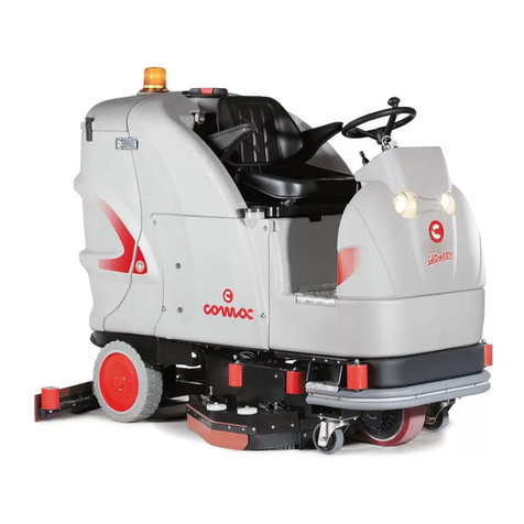
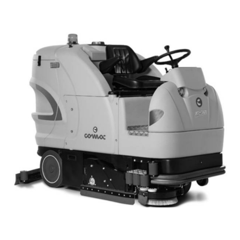
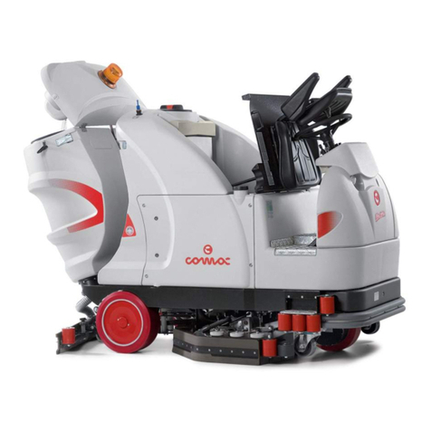
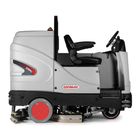
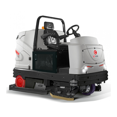
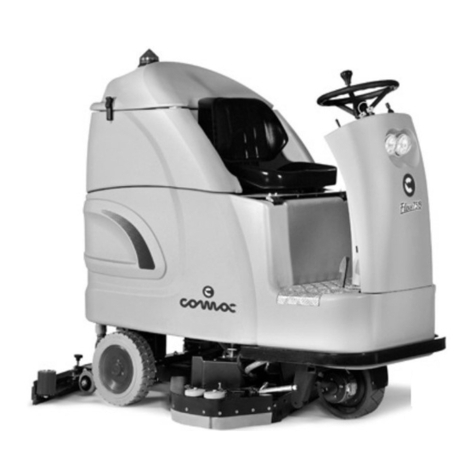
COMAC ULTRA 120 B-G User manual

ORIGINAL INSTRUCTION DOC. 10029463 - Ver. AC - 04-2016
SCRUBBING MACHINES
ULTRA 120 B-G
USE AND MAINTENANCE MANUAL


3
CONTENTS
CONTENTS...................................................................................................................................................... 3
SYMBOLS USED IN THE MANUAL ............................................................................................................... 5
MAIN MACHINE COMPONENTS.................................................................................................................... 6
PURPOSE AND CONTENT OF THE MANUAL............................................................................................ 11
TARGET GROUP........................................................................................................................................... 11
STORING THE USE AND MAINTENANCE MANUAL.................................................................................. 11
ON CONSIGNMENT OF THE MACHINE ...................................................................................................... 11
INTRODUCTORY COMMENT ....................................................................................................................... 11
IDENTIFICATION DATA................................................................................................................................. 11
TECHNICAL DESCRIPTION ......................................................................................................................... 11
INTENDED USE............................................................................................................................................. 11
SAFETY ......................................................................................................................................................... 11
SERIAL NUMBER PLATE ............................................................................................................................. 11
TECHNICAL DATA ........................................................................................................................................ 12
GENERAL SAFETY REGULATIONS............................................................................................................ 14
SYMBOLS USED ON THE MACHINE .......................................................................................................... 20
SYMBOLS USED ON THE CONTROL PANEL............................................................................................. 23
SYMBOLS USED ON THE SERIAL NUMBER PLATE................................................................................. 24
MACHINE PREPARATION ............................................................................................................................ 25
HANDLING THE PACKAGED MACHINE.................................................................................................................................25
TAKING THE MACHINE OUT OF ITS PACKAGING (B VERSIONS) ......................................................................................25
TAKING THE MACHINE OUT OF ITS PACKAGING (G VERSIONS)......................................................................................26
TRANSPORTING THE MACHINE (B VERSIONS) ..................................................................................................................28
TRANSPORTING THE MACHINE (G VERSIONS)..................................................................................................................29
TYPE OF BATTERY TO BE USED (B VERSIONS) .................................................................................................................31
TYPE OF BATTERY TO BE USED (G VERSIONS).................................................................................................................31
TYPE OF LPG CYLINDER TO BE USED (G VERSIONS).......................................................................................................31
MAINTENANCE AND DISPOSAL OF THE BATTERIES (B-G VERSIONS) ............................................................................31
MAINTENANCE AND DISPOSAL OF THE ENDOTHERMIC ENGINE (G VERSIONS)..........................................................31
MAINTENANCE AND DISPOSAL OF THE LPG CYLINDER (G VERSIONS) .........................................................................31
MACHINE SAFETY ..................................................................................................................................................................31
INSERTING THE BATTERIES IN THE MACHINE (B VERSIONS)..........................................................................................33
RECHARGING THE BATTERIES (B VERSION)......................................................................................................................33
INSERTING THE STARTER BATTERY (G VERSION) ............................................................................................................34
INSERTING THE LPG CYLINDER IN THE MACHINE (G VERSIONS)...................................................................................34
FILLING THE GASOLINE TANK (G VERSIONS).....................................................................................................................35
ASSEMBLING THE BRUSH.....................................................................................................................................................36
ASSEMBLING THE SQUEEGEE .............................................................................................................................................37
FILLING THE SOLUTION TANK ..............................................................................................................................................37
DETERGENT SOLUTION (VERSION WITHOUT CDS) ..........................................................................................................38
FILLING THE DETERGENT CANISTER (VERSIONS WITH CDS) .........................................................................................38
PREPARING TO WORK ................................................................................................................................ 39
CHECKING THE ENDOTHERMIC ENGINE (G VERSIONS) ..................................................................................................39
TRIGGERING THE HYDRAULIC SYSTEM .............................................................................................................................40

4
WORK ............................................................................................................................................................ 41
SWITCHING ON THE MACHINE (B VERSION) ......................................................................................................................41
SWITCHING ON THE MACHINE (G VERSION)......................................................................................................................41
WORK.......................................................................................................................................................................................42
BATTERY CHARGE LEVEL .....................................................................................................................................................43
SELECTING THE OPERATING DIRECTION...........................................................................................................................44
ADJUSTING THE OPERATING SPEED ..................................................................................................................................44
ADJUSTING THE PRESSURE ON THE BRUSHES................................................................................................................44
SIDEWAYS MOVEMENT OF THE BRUSH HEAD UNIT .........................................................................................................44
ADJUSTING THE SUPPLY OF DETERGENT SOLUTION ......................................................................................................45
DIPPED HEADLIGHTS.............................................................................................................................................................46
SERVICE BRAKE – PARKING BRAKE....................................................................................................................................46
BUZZER....................................................................................................................................................................................46
RECOVERY TANK FLOAT .......................................................................................................................................................46
SOLUTION TANK FLOAT.........................................................................................................................................................47
AT THE END OF THE WORK........................................................................................................................ 48
RECOMMENDED MAINTENANCE OPERATIONS ...................................................................................... 50
DRAINING THE RECOVERY TANK.........................................................................................................................................50
CLEANING THE SQUEEGEE UNIT.........................................................................................................................................51
CLEANING THE DISC BRUSHES ...........................................................................................................................................52
CLEANING THE VACUUM MOTOR FILTER............................................................................................................................53
DRAINING THE SOLUTION TANK ..........................................................................................................................................53
CLEANING THE RECOVERY TANK ........................................................................................................................................54
CLEANING THE SOLUTION TANK..........................................................................................................................................54
CLEANING THE DETERGENT SOLUTION FILTER................................................................................................................55
CLEANING THE SQUEEGEE VACUUM TUBE .......................................................................................................................55
CLEANING THE BRUSH HEAD SPLASH GUARD..................................................................................................................56
CLEANING THE DETERGENT TANK (VERSIONS WITH CDS) .............................................................................................57
CLEANING THE WATER SYSTEM (VERSION WITHOUT CDS)............................................................................................58
CLEANING THE WATER SYSTEM (VERSIONS WITH CDS) .................................................................................................58
MAINTENANCE OF THE ENDOTHERMIC ENGINE (G VERSIONS) .....................................................................................59
EXTRAORDINARY MAINTENANCE WORK ................................................................................................ 60
REPLACING THE BRUSH .......................................................................................................................................................60
REPLACING THE SQUEEGEE UNIT RUBBER BLADES .......................................................................................................60
REPLACING THE BRUSH HEAD SPLASH GUARD RUBBER ...............................................................................................61
REPLACING THE LPG CYLINDER (G VERSIONS)................................................................................................................62
REPLACING THE STARTER BATTERY (G VERSION) ...........................................................................................................62
ADJUSTMENT INTERVENTIONS................................................................................................................. 63
ADJUSTING THE SQUEEGEE UNIT RUBBER BLADES........................................................................................................63
TROUBLESHOOTING................................................................................................................................... 64
DISPOSAL ..................................................................................................................................................... 66
CHOOSING AND USING BRUSHES ............................................................................................................ 66
EC DECLARATION OF CONFORMITY......................................................................................................... 67

5
Warning symbol:
Carefully read the sections preceded by this symbol meticulously following the instructions indicated for the safety of the
operator and the device.
Covered place symbol:
The operations preceded by this symbol must always be carried out in a dry, covered area.
Danger symbol (moving carriages):
Indicates that the packed product should be handled with suitable carriages that conform to legal requirements.
Danger symbol (harmful gases):
Indicates the risk of inhaling gases that could harm the operator's health.
Disposal symbol:
Carefully read the sections marked with this symbol for disposing of the appliance.
Recycling symbol:
Tells the operator to carry out the operations in compliance with environmental regulations in force in the place where the
appliance is being used.
Symbol of the open book with i:
Indicates the need to consult the instruction manual.
The descriptions contained in this document are not binding. The company therefore reserves the right to make any modications at any time
to elements, details, or accessory supply, as considered necessary for reasons of improvement or manufacturing/commercial requirements.
The reproduction, even partial, of the text and drawings contained in this document is prohibited by law.
The company reserves the right to make any technical and/or supply modications. The images are shown as a reference only, and
are not binding as to the actual design and/or equipment.
Symbol of the open book:
Tells the operator to read the user manual before using the device.
Symbol indicating the compulsory use of protective gloves:
Indicates that the operator should always wear protective gloves, to avoid the risk of serious injury to his hands from sharp
objects.
Symbol indicating a treading ban:
Informs the operator that it is forbidden to tread on machine components, as this could lead to serious injury.
Symbol indicating the compulsory use of tools:
Informs the operator of the need to use tools not included with the machine.
Symbol indicating the compulsory need to air the room while recharging the batteries:
Informs the operator that the room must be aired while the batteries are being recharged.
Symbol forbidding the switch-on of the endothermic engine in closed places:
It is forbidden to switch on the machine and power it via the endothermic engine in closed or poorly aired places.
Symbol forbidding refuelling while the endothermic engine is switched on (or anyway hot):
It is forbidden to refuel when the engine is still running or still hot.
Symbol indicating that it is forbidden to approach with naked ames or electronic devices during refuelling:
Informs the operator that naked ames or electric devices must not be taken near the machine during refuelling operations.
Symbol forbidding the use of water for putting out res:
Informs the operator that it is forbidden to use water when attempting to put out a re.
Danger symbol (corrosive substances):
The operator should always wear protective gloves to avoid the risk of serious injury to the hands caused by corrosive
substances.
Danger symbol (battery acid leakage):
Indicates the danger of leaking acid or acid fumes from the batteries while they are being recharged.
SYMBOLS USED IN THE MANUAL
Information symbol:
Indicates additional information for the operator, to improve the use of the device.

6
MAIN MACHINE COMPONENTS
The front components of the machine are:
1. Filter retainer ring on vacuum cap
2. Starter battery (G version)
3. Squeegee unit vacuum nozzle
4. Side splash guard vacuum nozzle
5. Detergent level check bulb (CDS versions)
6. Vacuum cap
7. Side carter
8. Battery box (B version)
9. Vacuum cap retainer hinge
10. Recovery tank retainer hinge
11. Battery connector
12. Electrical system connector
13. Brush motor thermal circuit breaker
14. Vacuum motor thermal circuit breaker
15. Command display
16. Headlights
17. Starter battery retainer (G version)
18. LPG cylinder retainer (G version)
19. Rear rubber-pressing blade retainer
20. Gasoline tank lter (G versions)
21. Detergent solution lter
22. Solution tank inlet cap lter
23. Squeegee front rubber blade
24. Squeegee rear rubber blade
25. Rung
26. Quick female connection (CDS versions)
27. Quick male connection (CDS versions)
28. Machine tail-light command switch
29. Main key switch (B version)
30. Main key switch (G version)
31. External blade on splash guard rubber-pressing blade
32. Retainer blade for vacuum cap rotation
33. Internal blade on splash guard rubber-pressing blade
34. Front rubber-pressing blade
35. Rear rubber-pressing blade
36. Blinking light
37. Command lever for machine direction switch
38. Command lever for brush head sideways movement switch
39. Tap command lever
40. Command lever for engine air (G versions)
41. Parking brake lever
42. Engine rpm adjustment lever (G version)
43. Squeegee rotation release lever
44. Side splash guard movement handle
45. Handle for raising seat mounting plate
46. Command knob for selector switch for the fuel to be injected in
the endothermic engine carburettor
47. Command knob for switch to select the pressure on the
brushes
48. Command knob for working program selection switch
49. Command knob for working speed selection switch
50. Detergent percentage adjustment knob (CDS version)
51. Adjustment knob for quantity of water in the water system (CDS
version)
52. Spring safety clip
53. Control panel
54. Control panel (G version)
55. Front splash guard on brush head
56. External splash guard
57. Internal splash guard
58. Right side splash guard
59. Left side splash guard
60. Rear splash guard on brush head
61. Brake pedal
62. Drive pedal
63. Squeegee unit retainer knob
64. Knob for adjusting the height of the squeegee unit
65. Rubber-holder for optional quick solution tank lling kit
66. Vacuum cap lter guard
67. Buzzer button
68. Command display conrmation button
69. Gasoline bypass tap (G version)
70. Detergent solution bypass tap (CDS version)
71. Detergent solution lter tap
72. Operator seat
73. Gasoline tank (G version)
74. Detergent tank (CDS version)
75. Recovery tank
76. Solution tank
77. Red indicator light showing a traction engine fault
78. Red indicator light showing that the parking brake is ON
79. Red indicator light showing that the liquid in the solution tank
has reached reserve level
80. Red indicator light showing that the liquid in the recovery tank
has reached the overow level
81. Red indicator light showing that the liquid in the braking system
has reached a critical level
82. Red indicator light showing that the brush head engine is
working beyond the critical threshold
83. Green indicator light showing that the machine tail-lights are
working
84. Green indicator light showing that the brush head unit is back in
its standard position (inside the machine body)
85. Green indicator light showing that the squeegee unit has
reached its working position
86. Green indicator light showing that the left-hand vacuum motor
is functioning
87. Green indicator light showing that the right-hand vacuum motor
is functioning
88. Green indicator light showing that the electrical motor in the
brush head is functioning
89. Green indicator light showing that the solenoid valve in the
machine water system is functioning
90. Green indicator light showing that the main switch is functioning
(B versions)
91. Green indicator light showing that the main switch is functioning
(G versions)
92. Safety clip
93. Side splash guard retainer pin
94. Starter battery support (G version)
95. LPG cylinder support (G version)
96. Support for engine oil drainage tube (G versions)
97. Gasoline tank inlet cap (G versions)
98. Solution tank inlet cap
99. Cap of recovery tank maintenance drain well
100. Detergent tank cap (CDS version)
101. Cap for engine oil drainage tube (G versions)
102. Squeegee vacuum tube
103. Side splash guard vacuum tube
104. Gasoline tank level tube (G versions)
105. Engine oil drainage tube (G versions)
106. Recovery tank drainage tube
107. Solution tank drain pipe
108. Rubber-pressing blade retainer screw
109. Adjustment screw for squeegee tilt
110. Steering wheel
11
PURPOSE AND CONTENT OF THE MANUAL
TARGET GROUP
STORING THE USE AND MAINTENANCE MANUAL
ON CONSIGNMENT OF THE MACHINE
The aim of this manual is to provide customers with all the information needed to use the machine in the safest, most appropriate and
most autonomous way. This includes information concerning technical aspects, safety, operation, downtime, maintenance, spare parts and
scrapping. The operators and qualied technicians must carefully read the instructions in this manual before carrying out any operations on
the machine. If in doubt about the correct interpretation of instructions, contact your nearest Customer Service Centre to obtain the necessary
clarications.
This manual is written both for operators and for qualied machine maintenance technicians. Operators must not perform operations that
should be carried out by qualied technicians. The manufacturer is not liable for damages resulting from failure to comply with this veto.
The Use and Maintenance Manual must be stored in its special pouch close to the machine, protected from liquids and anything else that
could compromise its legibility.
When the machine is consigned to the customer, an immediate check must be performed to ensure all the material mentioned in the shipping
documents has been received, and also to check the machine has not suffered damage during transportation. If this is the case, the carrier
must ascertain the extent of the damage at once, informing our customer service ofce. It is only by prompt action of this type that the missing
material can be obtained, and compensation for damage successfully claimed.
IDENTIFICATION DATA
For technical assistance or to request replacement parts, always give the model, the version and the serial number (written on the relevant
plate).
TECHNICAL DESCRIPTION
INTENDED USE
SAFETY
SERIAL NUMBER PLATE
The ULTRA 120 is a oor scrubbing machine that can handle a wide variety of oors and types of dirt by using the mechanical action of two
disc brushes and the chemical action of a water-detergent solution. As it advances, it collects the dirt removed and the detergent solution not
absorbed by the oor. The machine must only be used for this purpose.
This scrubbing machine was designed and built for the cleaning (scrubbing and drying) of smooth, compact ooring in the commercial,
residential and industrial sectors by a qualied operator in proven safety conditions. The scrubbing machine is not suitable for cleaning rugs
or carpets. It is only suitable for use in closed (or at least covered) places.
ATTENTION: the machine is not suitable for use in the rain, or under water jets.
IT IS FORBIDDEN to use the machine for picking up dangerous dusts or inammable liquids in places with an explosive atmosphere.
In addition, it is not suitable as a means of transport for people or objects.
Operator cooperation is paramount for accident prevention. No accident prevention programme can be effective without the full cooperation
of the person directly responsible for machine operation. The majority of occupational accidents that happen either in the workplace or whilst
moving are caused by failure to respect the most basic safety rules. An attentive, careful operator is most effective guarantee against accidents
and is fundamental in order to implement any prevention programme. The manufacturer declines responsibility for any possible injury.
The serial number plate is located underneath the command panel. It
indicates the general machine characteristics, in particular the serial
number. The serial number is a very important piece of information
and should always be provided together with any request for
assistance or when purchasing spare parts.
INTRODUCTORY COMMENT
Any oor scrubbing machine can only work properly and effectively if used correctly and kept in full working order by performing the
maintenance operations described in the attached documentation. We therefore suggest you read this instruction booklet carefully and read it
again whenever difculties arise while using the machine. If necessary, remember that our assistance service (organised in collaboration with
our dealers) is always available for advice or direct intervention.

12
TECHNICAL DATA U/M ULTRA
120 B
ULTRA 120
G bi-fuel
ULTRA 120
G gasoline
Rated machine power W 5355
Working capacity up to m2/h 9600
Working width mm 1205
Squeegee width mm 1265
Brushes on brush head (number / Ø external bristles) No. / mm 2 / 610
Rpm of the single brush on the brush head rpm 115
Brush head engine (voltage / rated power) V / W 36 / 2000
Sideways movement of brush head mm 150
Maximum weight on the brushes kg 170
Traction motor (voltage / rated power) V / W 36 / 2000
Traction wheel (external Ø / width) mm 310 / 95
Maximum possible gradient % 10
Rear wheel (external Ø / width) mm 370 / 140
Maximum forward speed in transport mode km/h 8
Vacuum motor (number / voltage / rated power) No. / V
/ W 2 (36 - 670)
Vacuum on vacuum head mbar 190
Type of endothermic engine (G versions) - 4-stroke with overhead valve, 2
cylinders (two 90° V cylinders)
Endothermic engine capacity (G versions) cm3- 688
Net endothermic engine power (G versions) kW - 15.5 at 3600 rpm
Maximum net endothermic engine torque (G versions) Nm - 48.3 Nm at 2500 rpm
Endothermic engine cooling system (G versions) - Forced air
Maximum solution tank capacity l 280
Maximum recovery tank capacity l 285
Maximum capacity of the endothermic engine fuel tank (G versions) l - 17
Maximum detergent tank capacity (CDS version) 15 -
Steering diameter mm 3420
Machine length mm 2032
Machine width mm 1284
Machine height mm 1565(1)
Machine height (with optional roof) mm 2293
Machine pitch mm 1130
Machine wheel track mm 892
Battery compartment dimensions (width - length - useful height) mm 880 - 600 - 450 -
Starter battery compartment dimensions (width - length - useful height) mm - 229 - 135 - 165
Rated voltage of the battery box (recommended) (B versions) V / AhC536 - 480 -
Rated voltage of the starter battery (recommended) (G versions) V / AhC5- 12 - 45
Dimensions of the recommended cylinder (Ø / height) (G bi-fuel
versions) mm - 300 - 600 -

13
(1) For G bi-fuel versions, the value refers to the weight without the cylinder.
(2) For G bi-fuel versions, the value refers to the weight without the cylinder and with the gasoline tank empty.
(3) For G gasoline versions, the value refers to the weight with the gasoline tank empty.
1565
2185
2293
287346
633
377
1130
310 370
2032
1284
1266
1328
100 140
892
1192
1784
TECHNICAL DATA U/M ULTRA
120 B
ULTRA 120
G bi-fuel
ULTRA 120
G gasoline
Machine weight kg 760 1050 1039
Machine weight in transport mode kg 1275 1050(2) 1039(3)
Machine weight in working mode kg 1685 1366 1332
Maximum weight of the battery box (recommended) (B versions) kg 515 - -
Maximum weight of the recommended cylinder (tare weight + LPG)
(G bi-fuel versions) kg - 23 -
Sound pressure level (ISO 11201) - L pA dB (A) <70 <70 <70
Uncertainty KpA dB (A) 1.5 1.5 1.5
Hand vibration level (ISO 5349) m/s2< 2.5 < 2.5 < 2.5
Body vibration level (ISO 2631) m/s2< 0.5 < 0.5 < 0.5
Vibration measurement uncertainty 1.5% 1.5% 1.5%

14
The following regulations below must be carefully respected to
avoid harm to the operator and damage to the machine.
WARNING:
• Read the labels on the machine carefully. Do not cover them
for any reason, and replace them immediately if they become
damaged.
• The machine must be used and kept in closed places only (B
versions).
• The engine produces carbon monoxide which is a toxic gas.
Don't switch the engine on in closed places (G versions).
• Gasoline is highly ammable and explosive. Switch off the
engine and let it cool down before refuelling (G versions).
• The hot mufer can cause burns. Don't go near if the engine
has just been working (G versions).
• The bi-fuel version of the machine must not be kept in
underground or poorly aired places, near combustible materials
or electric systems, or near air vents, ducts and other openings
that communicate with underground rooms. In addition, the bi-
fuel version must not be kept in places with a classied re risk
(garages, etc.) (G bi-fuel versions).
• The machine must be exclusively used by authorised, trained
personnel.
• Do not use the machine on surfaces with a slope greater than
the one indicated on the serial number plate.
• The machine is not suitable for cleaning rough or uneven oors.
Do not use the machine on slopes.
• If you notice any damage to the battery recharging cable,
contact an authorised service centre straight away (B versions).
GENERAL SAFETY REGULATIONS

15
• In the event of a hazardous situation, quickly remove the battery
connector from the main system connector (both are located
beneath the seat mounting plate) (B versions).
• In the event of a hazardous situation, quickly remove the
alternator connector from the main system connector (both are
located beneath the seat mounting plate) (G versions).
• When doing maintenance work, switch off the machine using
the main switch. Remove the key from the instrument panel
and remove the battery connector from the electrical system
connector (B versions).
• When doing maintenance work, switch off the machine using
the main switch. Remove the key from the instrument panel
and remove the alternator connector from the electrical system
connector. Turn off the fuel ow adjustment tap. For the bi-fuel
version, close the valve in the LPG cylinder (G versions).
• To prevent unauthorised machine use, the power supply
should be interrupted: switch the machine off using the main
switch, remove the key from the block and remove the battery
connector from the electrical system connector (B versions).
• To prevent unauthorised machine use, the power supply should
be interrupted: switch the machine off using the main switch,
remove the key from the block and remove the alternator
connector from the electrical system connector (G versions).
• Children must be supervised to ensure they do not play with
the machine.
• During the working of the machine, pay attention to other
people and especially to children.
• Only use the brushes supplied with the machine, or those
specied in the "CHOOSING AND USING THE BRUSHES"
paragraph of the instruction manual. The use of other brushes
could be unsafe.

16
• The machine must only be powered with a voltage equal to that
shown on the serial number plate. (B versions).
• If the machine is left unattended, it must be protected from any
accidental movements.
• The machine must be regularly inspected by a qualied person,
especially with regards the LPG tank and its connections, as
required by local or national safety regulations.
• When replacing the LPG cylinder, stay far from ames, cinders
or active electric devices. Before replacing it, make sure the
taps of both the old and the new cylinders are turned off (G bi-
fuel versions).
• The seal between the tap and the regulator must be changed
every time the cylinder is changed (G bi-fuel versions).
• After replacing the cylinder, carry out a seal test on the
connections using soapy water (never use ames for this
purpose). After this, perform a machine switch-on test (G bi-
fuel versions).
• If you smell gas, turn off the supply (cylinder tap); air the room
well, bearing in mind that LPG is heavier than air and spreads
at ground level. Have the system checked by specialised
personnel (G bi-fuel versions).
• After every use, turn off the cylinder valve tap (G bi-fuel
versions).
• Non-connected cylinders - whether full, partially full, empty or
presumed empty - must never be kept on the user's premises
(G bi-fuel versions).
• The refuelling place must be well aired. Never refuel the engine
inside a building where the gasoline fumes could come into
contact with ames or sparks.
• Do not refuel when the engine is still hot.
• You are advised to always put on protective gloves before

17
handling the fuel, to avoid any risk of serious injury to your
hands.
• For the characteristics of the recommended fuel, refer to the
Use and Maintenance Manual of the endothermic engine.
• Gasoline is highly and easily ammable. Keep away from res
and do not shake fuel containers. Don't smoke in the refuelling
area! Discharge any static electricity from your body before
approaching the fuel tank.
• Carry out refuelling operations in well-aired places only.
• Before refuelling, always switch off the engine.
• Always open the tank cap carefully, to slowly discharge the
overpressure and prevent fuel from spurting out.
• Don't inhale the fuel vapours.
• Fuels may contain substances similar to solvents. Avoid
any contact of mineral oil products with the skin and eyes.
Use gloves when refuelling. Change your protective clothes
frequently, and clean them.
• Make sure fuel doesn't seep into the ground (environmental
protection).
• In the event of a fuel leakage, clean the machine immediately.
• After refuelling, replace the tank cap.
• Tighten it rmly, but without using tools. The cap must not come
loose while the machine is being used.
• Check the tank for any leaks or ineffective seals. If you notice a
fuel leakage, do not switch on or use the machine.
• Keep the fuel in containers that meet the legal requisites and
bear an identication label.

18
ATTENTION:
• The machine must not be used or stored outdoors in damp
conditions or directly exposed to rain.
• The appliance must be stored in a closed area with a temperature
between -25°C and +55°C.
• Conditions of use: room temperature between 0°C and 40°C,
with relative humidity between 30 and 95%.
• The socket for the battery charger cable must have a prescribed
earth connection (B versions).
• The machine does not cause harmful vibrations.
• Never collect gases, explosive/inammable liquids or powders,
nor acids and solvents! These include gasoline, paint thinners
and fuel oil (which, when mixed with the vacuum air, can form
explosive vapours or mixtures), and also non-diluted acids
and solvents, acetones, aluminium and magnesium powders.
These substances may also corrode the materials used to
construct the machine.
• If the machine is used in dangerous areas (e.g. petrol stations),
the relative safety standards must be observed. It is forbidden
to use the machine in environments with a potentially explosive
atmosphere.
• Do not place any liquid containers on the machine.
• In the event of a re, use a powder extinguisher. Do not use
water.
• Adapt the speed to the adhesion conditions.
• Avoid working with the brushes when the machine is standing
still, so as to avoid damage to the oor.
• Do not knock against shelving or scaffolding, where there
is a danger of falling objects. The operator must always be
equipped with the appropriate safety devices (gloves, shoes,

19
helmet, goggles, etc.).
• If the machine does not work properly, check this is not caused
by failure to carry out routine maintenance. Otherwise, ask for
intervention of the authorised technical assistance centre.
• If you need to replace any components, request the ORIGINAL
spare parts from an Authorised Retailer or dealer.
• Restore all electrical connections after any maintenance
interventions.
• Have the machine checked by an authorised technical
assistance centre every year.
• When disposing of consumable materials, observe the laws
and regulations in force. When your machine has reached the
end of its long working life, dispose of the materials it contains
in an appropriate manner, and bearing in mind that the machine
itself was constructed using fully recyclable materials.

20
Recovery tank drainage tube label:
Located on the rear part of the machine, to identify the recovery tank drainage tube.
Solution tank drainage tube label:
Located on the rear part of the machine, to identify the solution tank drainage tube.
Parking brake lever label:
Located near the operator seat, to identify the command lever of the parking brake.
SYMBOLS USED ON THE MACHINE
Braking system oil level check label:
Located near the braking system oil basin, to remind the operator to check the level of oil in the basin.
The bottom part of the label shows the recommended oil for the braking system.
Label warning about the risk of crushed hands:
Indicates danger to hands due to crushing between two surfaces.
Label warning about sideways brush head movement:
Located on the right-hand side of the machine, to warn that the brush head can move sideways.
Label indicating the need to read the Use and Maintenance Manual:
Located near the steering column, to remind the operator to read the Use and Maintenance Manual before
using the machine.
Label indicating that ammable/esplosive dusts and/or liquids must not be vacuumed:
Located near the steering column, to indicate that it is forbidden to vacuum ammable or explosive dusts or
liquids with the machine.
Battery recharging and daily care label:
Located near the steering column, indicating how to recharge the batteries. On the side, it reminds the operator
of the need to clean the squeegee and all the machine lters every day.
Table of contents
Other COMAC Scrubber manuals

COMAC
COMAC agila bto User manual

COMAC
COMAC Vega 2019 User manual

COMAC
COMAC ULTRA120 B User manual

COMAC
COMAC Tripla 65 User manual

COMAC
COMAC ANTEA 50 B User manual

COMAC
COMAC Optima 90 User manual

COMAC
COMAC SCRUB 45D User manual

COMAC
COMAC ABILA 52 User manual

COMAC
COMAC C85B-C100B User manual

COMAC
COMAC INNOVA 65 B M 2011 User manual

COMAC
COMAC SIMPLA 500E User manual

COMAC
COMAC VISPA 35B Instruction manual

COMAC
COMAC SIMPLA 45 Manual

COMAC
COMAC Vispa 35E User manual

COMAC
COMAC ULTRA 85B User manual

COMAC
COMAC OPTIMA 85 User manual

COMAC
COMAC OMNIA 26 User manual

COMAC
COMAC C85 ESSENTIAL Series User manual

COMAC
COMAC Innova Comfort User manual

COMAC
COMAC SIMPLA 50 B User manual