ComAp Aquatis Service manual

Mounting and operating instructions
ABRI 820254 - 05/19 - ind. A
COMAP Group
Registered oce: 16 avenue Paul Santy - B.P. 8211
F-69355 LYON CEDEX 08 - FRANCE
Tel. +33 (0)4 78 78 16 00 - Fax +33 (0)4 78 78 16 95
www.comap-group.com

1
ABRI 820254 - 05/19 - ind. A
1. Important recommendations 2
1.1. Important safety instructions 2
1.2. Prior to installation 2
1.3. The tools you will need 3
2. Description 4
2.1. Technical characteristics 4
2.2. How to use the device 5
3. Control panel operation 6
3.1. The control panel 6
3.2. Operating statuses 6
4. Prior to installation 7
4.1. Checkingttings 7
5. Installation 9
5.1. Preparing the wall/supporting structure 9
5.2. Preparing for connection 9
5.3. Mounting the Aquatis 10
5.4. Hydraulic connection and installing the tap 10
5.5. Installing cartridges 13
5.6. Connectingtheowsensor 13
5.7. InsertthebatteriesforthePCB 13
5.8. Commissioning 14
6. Replacing consumables 15
6.1. Handling 15
6.2. Listofspareparts 17
Contents

2
COMAP GROUP - 16, avenue Paul Santy - BP 8211 - 69355 LYON Cedex 08 - FRANCE
//
Aquatis
1. Important recommendations
Before using this device, please read this guide carefully and keep it for future reference. Only use this
device for its intended purpose and in accordance with the instructions provided in the guide. Thisdevice
must not be used by children under the age of 8 and by people with restricted physical, sensory ormental
capacities or by people with no experience or knowledge, unless they are properly supervised or ifthey have
been given instructions on safe use of the device and have understood the risks involved. Children must
not play with the device. Cleaning and maintenance by the user must not be carried out by unsupervised
children. The warnings and important safety instructions in this guide do not purport tocover every situation
that is likely to occur. It is your responsibility to apply common sense and caution during installation,
maintenance and operation of the device.
Do not modify the device.
Do not climb onto the device. Do not place any objects (such as laundry, lit candles, lit cigarettes, metal
objects, etc.) on the device.
Do not place any containers of water or filter bowls on the device.
Contact the technical support department for help: +44 1942 603 351.
1.1. Important safety instructions
1.2. Prior to installation
Install the device on a cold water system (temperature between 2 °C and 38 °C).
If the pressure in your cold water system exceeds 4 bar, a pressure reducing valve must be installed.
Ensure that your device is located in a temperate location (temperature between 5 °C and 35 °C).
Do not install the device in a location where it is exposed to direct sunlight or near a cooker, heater
orother devices.
Do not use aerosols near the device. Do not install this device in a location where gas leaks may occur.
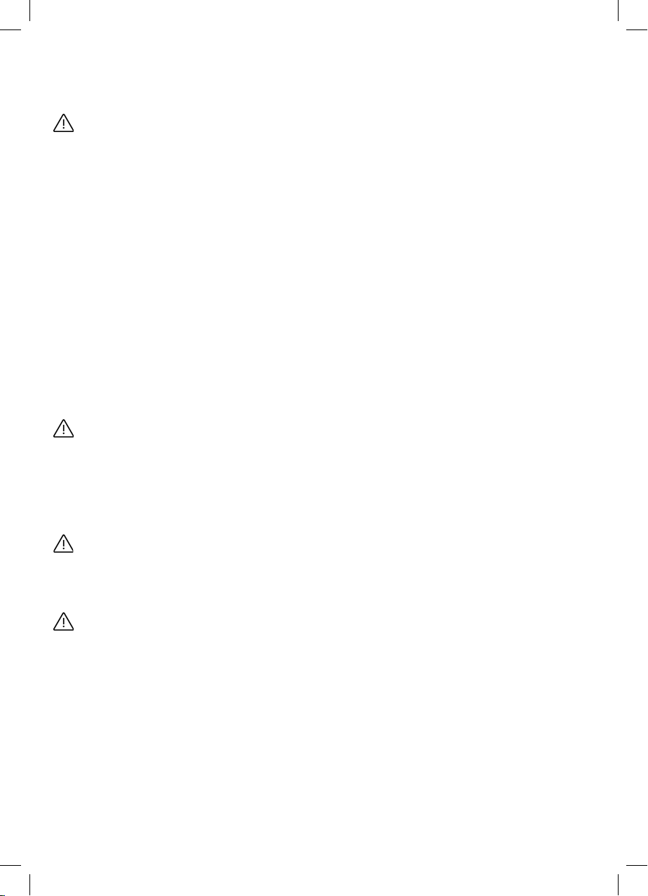
Secure the device to the wall on a solid surface, which is able to support 6 kg on three mounting points.
The wall plugs provided are intended for use in materials such as concrete. For other types of material,
use appropriate mounting hardware.
Do not install this device near a heat source or a flammable material.
Do not install this device in a damp, oily or dusty environment, or in a location where it is exposed todirect
sunlight or water.
Do not place the product beneath anything that could be the source of a leak (pipes, taps, valves, etc.).
We recommended using a qualified technician or a repair company to install or repair the device.
Changes and modifications to this device by a third party are not covered by COMAP's warranty service.

3
ABRI 820254 - 05/19 - ind. A
COMAP accepts no liability in the event of safety issues or damage resulting from modifications made
by a third party.
Adhere to the useful life of consumables and replace them in strict accordance with the instruction manual.
Do not attempt to repair, dismantle or modify the device yourself.
This instruction manual is a guide to installing the Aquatis. The illustrations it contains are not contractual.
Take care not to reverse the battery polarity.
1.3. The tools you will need
• Felt-tip pen or pencil.
• Drill with a 6 mm bit for securing to a solid surface.
• Philips electric or manual screwdriver.
• Wrench.
• Spirit level.
• Cutter.
• Tape measure.

4
COMAP GROUP - 16, avenue Paul Santy - BP 8211 - 69355 LYON Cedex 08 - FRANCE
//
Aquatis
2. Description
• 1st characteristic: filtration of sediment, chlorine tastes and smells, using activated carbon (10µm).
• 2nd characteristic: filtration of pesticides and herbicides using activated carbon (10µm).
• 3rd characteristic: filtration of bacteria and viruses using a hollow fibre membrane (0.1µm).
• PCB powered by a battery pack with 2 x 1.5V AA LR6 batteries (supplied).
• Three colour visual (green, orange, red) and audible (buzzer) indicator of the wear status of consumables.
• Operating pressure: 0.5 bar - 4 bar.
• Min. - max. water temperature: 2 - 38 °C.
• Flow sensor.
• Water filtering rate: 120 l/h
• Ø ¼” Inlet/Outlet.
• Dimensions: 36 x 27.5 x 9 cm.
• Total space required: 50 x 27.5 x 9 cm needed in order to be able to replace the filters.
• Weight: 6 kg.
2.1. Technical characteristics
A Filter wear control panel
B Cover equipped with the PCB for managing filter wear
C Anti-sediment, chlorine taste and smell cartridge (10 µm)
D Anti-pesticide and herbicide cartridge (10 µm)
E Ultra-filtration cartridge (0.1 µm)
F Filter head and flow sensor bracket
Water flow direction: C->D->E (1->2->3)
AB
C
DE
123123
F
123
123
123
PURE
+-
-
+
PURE
(x2)
(x1)
PE 1/4"
1 2 3
123
123
123
PURE
+-
-
+
PURE
(x2)
(x1)
PE 1/4"
1 2 3

5
ABRI 820254 - 05/19 - ind. A
2.2. How to use the device
Device intended for drinking water, for connection to the mains water supply.
The filter life depends on the quantity and quality of the water treated and the usage time, for hygiene
reasons.
The flow direction must be adhered to, a reversal will aect the device's operation and performance,
and the warranty will no longer be valid.
When commissioning the device, rinse cartridges for a few minutes by letting the tap water run before
drinking the filtered water.
Do not store the water in bottles for more than 24 hours.

6
COMAP GROUP - 16, avenue Paul Santy - BP 8211 - 69355 LYON Cedex 08 - FRANCE
//
Aquatis
3. Control panel operation
3.1. The control panel
A control panel provides a view of the wear status of filters and indicates when they need to be replaced.
The panel has 3 lights j, kand l, which can be green, orange or red and 3 buttons A, B and C.
The lights j, kand lcorrespond to filters 1, 2 and 3 respectively. A buzzer (audible alarm) also informs
users of the need to replace the filter in a situation where the device is not visible (e.g.: under a sink).
The lights come on each time water is drawn or if one of the buttons is pressed.
j Status of filter 1 A Reset button for filter 1
k Status of filter 2 B Reset button for filter 2
l Status of filter 3 C Reset button for filter 3
3.2. Operating statuses
Light colour Buzzer (audible alarm) Meaning
Green - Filter status OK
Orange Two audible beeps Schedule a filter replacement
Flashing red Alternating short audible beeps
over a long period
The filter needs to be replaced
Alternating 3 lights flashing red Alternating long audible beeps The batteries will soon be flat,
replace them
j k l
A B C

7
ABRI 820254 - 05/19 - ind. A
4. Prior to installation
Install the tap, by referring to its instruction manual.
4.1. Checking fittings
STOP OK
+
50 cm
27,5 cm
9 cm
•
•
•
•
•
LR6 - AA
LR6 - AA
•
•
•
•
•
BIP - BIP
1 2 3
123
12
3
123
123
23
1
OK
--
+--
123
Aquatis 1-way or 3-way tap
(optional)
3 filter cartridges Bag of fittings
1 Under-sink wedge for low thickness stainless
steel models *
9 Hose
2 Under-tap washer * 10 Card and sticker for operating instructions
3 Tap tightening tool * 11 Wall plugs
4 Cold water hose T-piece connector 12 Stop valve
5 Tap warranty booklet 13 Half-moon tap fixing washer *
6 2 x LR6 – AA 1.5V batteries 14 A number of connectors available
for the option without a tap
7 Teflon sealing tape 15 Metal filter tool
8 Ø1/4” connecting hose 16 Food grade silicone grease.
* Depends on the chosen option
STOP OK
+
50 cm
27,5 cm
9 cm
•
•
•
•
•
LR6 - AA
LR6 - AA
•
•
•
•
•
BIP - BIP
1 2 3
123
12
3
123
123
23
1
OK
--
+--
123
12
3
5
6
7
10
9
8
11
12
13
14
4
15
Optional items
16

8
COMAP GROUP - 16, avenue Paul Santy - BP 8211 - 69355 LYON Cedex 08 - FRANCE
//
Aquatis
Device dimensions: 36 x 27.5 x 9 cm.
Allow sucient space against the wall of 50 x 27.5 x 9 cm, which equates to the space needed to replace
filter cartridges.
STOP OK
+
50 cm
27,5 cm
9 cm
•
•
•
•
•
LR6 - AA
LR6 - AA
•
•
•
•
•
BIP - BIP
1 2 3
123
123
123
123
23
1
OK
--
+--
123
27.5 cm
50 cm
9 cm

9
ABRI 820254 - 05/19 - ind. A
5. Installation
5.1. Preparing the wall/supporting structure
You can use the filter head bracket to mark the mounting points. Use a spirit level to ensure the position is correct.
Then drill out the Ø of screws or wall plugs, depending on the mounting bracket. Now insert the 2 top screws.
5.2. Preparing for connection
STOP OK
+
50 cm
27,5 cm
9 cm
•
•
•
•
•
LR6 - AA
LR6 - AA
•
•
•
•
•
BIP - BIP
1 2 3
123
12
3
123
123
23
1
OK
--
+--
123
Prepare to fit the stop valve on the connector using PTFE tape (Teflon).
Add between 15 and 20 layers of Teflon to the stop valve’s male thread to create a seal. Screw it onto the connector.
Be careful not to apply too much tightening force as this could break the stop valve. This breakage,
orthe damage caused, will not be covered by the warranty.
Then connect one end of the pipe to the stop valve. Tighten this connection using the wrench.
Apply food grade grease, using the tube provided, to the stop valve’s inlet to make it easier to insert.
STOP OK
+
50 cm
27,5 cm
9 cm
•
•
•
•
•
LR6 - AA
LR6 - AA
•
•
•
•
•
BIP - BIP
1 2 3
123
12
3
123
123
23
1
OK
--
+--
123
STOP OK
+
50 cm
27,5 cm
9 cm
•
•
•
•
•
LR6 - AA
LR6 - AA
•
•
•
•
•
BIP - BIP
1 2 3
123
12
3
123
123
23
1
OK
--
+--
123
STOP OK
+
50 cm
27,5 cm
9 cm
•
•
•
•
•
LR6 - AA
LR6 - AA
•
•
•
•
•
BIP - BIP
1 2 3
123
123
123
123
23
1
OK
--
+--
123
STOP OK
+
50 cm
27,5 cm
9 cm
•
•
•
•
•
LR6 - AA
LR6 - AA
•
•
•
•
•
BIP - BIP
1 2 3
123
123
123
123
23
1
OK
--
+--
123

10
COMAP GROUP - 16, avenue Paul Santy - BP 8211 - 69355 LYON Cedex 08 - FRANCE
//
Aquatis
123
123
123
PURE
+-
-
+
PURE
(x2)
(x1)
PE 1/4"
1 2 3
5.3. Mounting the Aquatis
Remove the cover and mount the device on the bracket.
5.4. Hydraulic connection and installing the tap
Step 1:
• Turn o the water supply for your kitchen or, failing this, for your home.
Step 2:
• Open the tap to reduce the pressure in the system.
Step 3:
• When replacing a tap, only install the hose on the hot water inlet. The hose on the cold water inlet will
beinstalled in the following steps. To do this, refer to step 7.1. If you are keeping your existing tap, simply
unscrew the cold water inlet hose.
STOP
OK
+
50 cm
27,5 cm
9 cm
•
•
•
•
•
LR6 - AA
LR6 - AA
•
•
•
•
•
BIP - BIP
1 2 3
123
12
3
123
123
23
1
OK
--
+--
123
STOP OK
+
50 cm
27,5 cm
9 cm
•
•
•
•
•
LR6 - AA
LR6 - AA
•
•
•
•
•
BIP - BIP
1 2 3
123
123
123
123
23
1
OK
--
+--
123
STOP OK
+
50 cm
27,5 cm
9 cm
•
•
•
•
•
LR6 - AA
LR6 - AA
•
•
•
•
•
BIP - BIP
1 2 3
123
123
123
123
23
1
OK
--
+--
123
STOP OK
+
50 cm
27,5 cm
9 cm
•
•
•
•
•
LR6 - AA
LR6 - AA
•
•
•
•
•
BIP - BIP
1 2 3
123
12
3
123
123
23
1
OK
--
+--
123

11
ABRI 820254 - 05/19 - ind. A
Step 4:
Screw the pre-assembled connector onto the cold water inlet. Now connect the hose to the pre-assembled
connector.
Ensure that the seal is present between the parts before tightening them.
Step 5:
Thread the white pipe through the hole in the bottom left of the bracket, then align it with the device's inlet
connector and cut it to the correct length using the cutter, to enable it to be inserted into the connector.
Insert the white pipe adjusted to the correct length through the hole in the bottom left of the bracket and then
into the device’s inlet connector.
Once installed, check that the pipe is securely mounted in the connector by pulling it.
Pay attention to the device's connection direction. Ensure that you pass the pipe through the hole (1).
Step 6:
• In the same way as for the inlet pipe, cut the Aquatis outlet pipe to the correct size. Connect it to the device's
OUT outlet. Pass the pipe through hole 2.
The pipe is connected using an automatic push-fit connector. If necessary, to disconnect the pipe connector,
push the white washer while simultaneously pulling the pipe downwards.
123
123
123
PURE
+-
-
+
PURE
(x2)
(x1)
PE 1/4"
1 2 3
1
IN
STOP OK
+
50 cm
27,5 cm
9 cm
•
•
•
•
•
LR6 - AA
LR6 - AA
•
•
•
•
•
BIP - BIP
1 2 3
123
12
3
123
123
23
1
OK
--
+--
123
STOP OK
+
50 cm
27,5 cm
9 cm
•
•
•
•
•
LR6 - AA
LR6 - AA
•
•
•
•
•
BIP - BIP
1 2 3
123
12
3
123
123
23
1
OK
--
+--
123
123
123
123
PURE
+-
-
+
PURE
(x2)
(x1)
PE 1/4"
1 2 3
OUT
2
STOP OK
+
50 cm
27,5 cm
9 cm
•
•
•
•
•
LR6 - AA
LR6 - AA
•
•
•
•
•
BIP - BIP
1 2 3
123
123
123
123
23
1
OK
--
+--
123
OUT
2
OR
For disconnection if necessary.

12
COMAP GROUP - 16, avenue Paul Santy - BP 8211 - 69355 LYON Cedex 08 - FRANCE
//
Aquatis
Step 7:
• Ensure that the plastic connector is properly installed on the tap’s filtered water inlet. Remove the blue
strip from the connector then clip the Aquatis outlet pipe onto the pure filtered water tap connector.
Check that there is a good mechanical connection by pulling the pipe.
• The 3-way tap is installed instead of your current tap. Check the size of your current tap's opening
byinserting the 3-way tap.
• Installation of the 1-way tap requires an additional hole to be drilled in your worktop. Use suitable tools
for your sink's or your worktop's material with the correct diameter. Check in advance that the drilled
hole will be in an accessible position to allow mounting to proceed. Should you be in any doubt, employ
a professional.
123
123
123
PURE
+-
-
+
PURE
(x2)
(x1)
PE 1/4"
1 2 3
123
123
123
PURE
+-
-
+
PURE
(x2)
(x1)
PE 1/4"
1 2 3
Similar operation for the 1-way
or 3-way version
}
STOP OK
+
50 cm
27,5 cm
9 cm
•
•
•
•
•
LR6 - AA
LR6 - AA
•
•
•
•
•
BIP - BIP
1 2 3
123
12
3
123
123
23
1
OK
--
+--
123
STOP OK
+
50 cm
27,5 cm
9 cm
•
•
•
•
•
LR6 - AA
LR6 - AA
•
•
•
•
•
BIP - BIP
1 2 3
123
12
3
123
123
23
1
OK
--
+--
123
OR

13
ABRI 820254 - 05/19 - ind. A
5.5. Installing cartridges
Apply food grade silicone grease to the seals or wet them with water in advance. Adhere to positions
1, 2 and 3 based on the number appearing on the cartridge label from left to right. Place the cartridge
tobeinserted beneath the corresponding position. To match the cartridge to Aquatis, position it between
the two faces showing information. Once engaged, rotate the cartridge a quarter turn to the right. Thelabel
should appear on the front when looking at the device.
5.6. Connecting the flow sensor
Ensure that you observe the mounting direction for the flow sensor connector (see photos opposite).
If it does not fit, do not force it. Take care not to touch the PCB with wet fingers.
5.7. Insert the batteries for the PCB
Ensure that the polarity of the LR6-AA batteries is correct.
Once inserted, the three lights on the Aquatis should light up in green. If they do not light up, check that the
batteries have been inserted in the correct direction.
STOP OK
+
50 cm
27,5 cm
9 cm
•
•
•
•
•
LR6 - AA
LR6 - AA
•
•
•
•
•
BIP - BIP
1 2 3
123
12
3
123
123
23
1
OK
--
+--
123
STOP OK
+
50 cm
27,5 cm
9 cm
•
•
•
•
•
LR6 - AA
LR6 - AA
•
•
•
•
•
BIP - BIP
1 2 3
123
12
3
123
123
23
1
OK
--
+--
123
STOP OK
+
50 cm
27,5 cm
9 cm
•
•
•
•
•
LR6 - AA
LR6 - AA
•
•
•
•
•
BIP - BIP
1 2 3
123
123
123
123
23
1
OK
--
+--
123
STOP OK
+
50 cm
27,5 cm
9 cm
•
•
•
•
•
LR6 - AA
LR6 - AA
•
•
•
•
•
BIP - BIP
1 2 3
123
123
123
123
23
1
OK
--
+--
123
STOP OK
+
50 cm
27,5 cm
9 cm
•
•
•
•
•
LR6 - AA
LR6 - AA
•
•
•
•
•
BIP - BIP
1 2 3
123
12
3
123
123
23
1
OK
--
+--
123
}
STOP OK
+
50 cm
27,5 cm
9 cm
•
•
•
•
•
LR6 - AA
LR6 - AA
•
•
•
•
•
BIP - BIP
1 2 3
123
123
123
123
23
1
OK
--
+--
123

14
COMAP GROUP - 16, avenue Paul Santy - BP 8211 - 69355 LYON Cedex 08 - FRANCE
//
Aquatis
Secure the cover by attaching it to the mounting brackets at the top and then by engaging the clips at the bottom.
It is possible to adjust the tightness of the fitting using the oblong hole at the bottom of the bracket.
E.g.: if the cover is too tight to unclip, loosen the centre screw and realign the holes in the bottom of the bracket.
5.8. Commissioning
Gradually open the system’s main stop valve followed the Aquatis stop valve.
Ensure there are no leaks for 48 hours, by carrying out visual inspections.
Open the tap used for filtered water and leave the water to run for a few minutes using the small lever on the
filtered water channel, in order to rinse the cartridges. While water is flowing, check that the 3 lights are on;
thismeans that the device is connected correctly (hydraulically and electrically).
Please note that the water may look cloudy during the first few uses. This is caused by small air
bubbles, which are forced out of the pre-filtration and ultra-filtration cartridges, which filter at 10 µm
and 0.1 µm respectively. The water is 100% drinkable and of a very high quality.
This phenomenon may last until all the micro air bubbles have been forced out (this depends on the mains
pressure and that of the hydraulic system).
Outlet
STOP OK
+
50 cm
27,5 cm
9 cm
•
•
•
•
•
LR6 - AA
LR6 - AA
•
•
•
•
•
BIP - BIP
1 2 3
123
123
123
123
23
1
OK
--
+--
123
STOP OK
+
50 cm
27,5 cm
9 cm
•
•
•
•
•
LR6 - AA
LR6 - AA
•
•
•
•
•
BIP - BIP
1 2 3
123
123
123
123
23
1
OK
--
+--
123
3
Inlet
STOP OK
+
50 cm
27,5 cm
9 cm
•
•
•
•
•
LR6 - AA
LR6 - AA
•
•
•
•
•
BIP - BIP
1 2 3
123
123
123
123
23
1
OK
--
+--
123
12
Inlet / Outlet
STOP OK
+
50 cm
27,5 cm
9 cm
•
•
•
•
•
LR6 - AA
LR6 - AA
•
•
•
•
•
BIP - BIP
1 2 3
123
123
123
123
23
1
OK
--
+--
123
12

15
ABRI 820254 - 05/19 - ind. A
6. Replacing consumables
The control panel informs you:
It automatically calculates the remaining life on the basis of consumption and the time since installation.
Part numbers:
1 SC: Q112020001
2 HP: Q112021001
3 BU: Q112022001
Alarm:
Cartridge(s) worn (orange light + beeps).
Cartridge(s) unserviceable, require replacement (red light + beeps).
Batteries flat, require replacement (3 alternate flashing red lights + beeps).
6.1. Handling
The filters can be replaced at any time. In order not to have water running from cartridges when replacing them,
proceed as follows:
1. Open the filter tap and leave the filtered water to run. While the water is running, cut o the water inlet
by rotating the Aquatis tap stop valve a quarter turn to the right. The valve’s fins must be perpendicular
tothe pipe. A small amount of water will continue to run from the filter tap. Once the water stops running,
close the tap using the small lever that controls the filtered water.
STOP
OK
+
50 cm
27,5 cm
9 cm
•
•
•
•
•
LR6 - AA
LR6 - AA
•
•
•
•
•
BIP - BIP
1 2 3
123
12
3
123
123
23
1
OK
--
+--
123
2. Prepare the replacement cartridge by removing it from its protective bag.
3. Remove the cartridge by rotating it a quarter turn to the left, by slotting the metal filter tool into the
indentation in the bottom of the cartridge designed for this purpose.

16
COMAP GROUP - 16, avenue Paul Santy - BP 8211 - 69355 LYON Cedex 08 - FRANCE
//
Aquatis
CAUTION: keep the cartridges vertical as they are still full of water.
4. Insert the new cartridge by pushing it up and then turning it to the right, with the seals previously
coated with food grade silicone grease.
STOP OK
+
50 cm
27,5 cm
9 cm
•
•
•
•
•
LR6 - AA
LR6 - AA
•
•
•
•
•
BIP - BIP
1 2 3
123
123
123
123
23
1
OK
--
+--
123
5. Once the cartridge has been installed, press and hold the corresponding button for the cartridge for
5 seconds until the green light flashes rapidly twice and you hear two rapid audible beeps. This signal
indicates that the cartridge has been reset.
STOP OK
+
50 cm
27,5 cm
9 cm
•
•
•
•
•
LR6 - AA
LR6 - AA
•
•
•
•
•
BIP - BIP
1 2 3
123
12
3
123
123
23
1
OK
--
+--
123
6. Re-open the water inlet.
STOP
OK
+
50 cm
27,5 cm
9 cm
•
•
•
•
•
LR6 - AA
LR6 - AA
•
•
•
•
•
BIP - BIP
1 2 3
123
12
3
123
123
23
1
OK
--
+--
123
7. Leave the water to run for several minutes to rinse the cartridge. The water may have a whitish orcloudy
appearance. This is caused by small air bubbles, which are forced out of the pre-filtration and ultra-
filtration cartridges. The water is 100% drinkable and of a very high quality. This phenomenon may
last until all the micro air bubbles have been forced out (this depends on the mains pressure and that
ofthehydraulic system).
STOP OK
+
50 cm
27,5 cm
9 cm
•
•
•
•
•
LR6 - AA
LR6 - AA
•
•
•
•
•
BIP - BIP
1 2 3
123
123
123
123
23
1
OK
--
+--
123

17
ABRI 820254 - 05/19 - ind. A
6.2. List of spare parts
Spare parts will be available for 5 years from the final date on which the product is manufactured.
Name Period Part number
Cartridge 1 5 years Q112020001
Cartridge 2 5 years Q112021001
Cartridge 3 5 years Q112022001
PCB 5 years RI550245
Table of contents
Popular Water Filtration System manuals by other brands

Franke
Franke KER1P Installation instructions and user guide

Grunbeck
Grunbeck BOXER KX Operation manual

Brita
Brita OPFF-100 user guide

Pneumatech
Pneumatech PMH C Instruction book

Panasonic
Panasonic ET-RFF200 operating instructions

Antunes Filtration Technologies
Antunes Filtration Technologies SE-4200/4400 owner's manual