COMBAT BH-COMPLETE Guide

1
Improper installation, adjustment, alteration, service
or maintenance can result in death, injury or property
damage. Read the Installation, Operation and Service
manual thoroughly before installing or servicing this
equipment.
Installation must be done by a registered installer/
contractor qualified in the installation and service of
gas-fired equipment or your gas supplier.
FOR YOUR SAFETY
If you smell gas:
1. Open windows.
2. DO NOT try to light any appliance.
3. DO NOT use any telephone in your
building.
4. Extinguish any open flame.
5. Leave the building.
6. Immediately call your local fuel supplier
after leaving the building.
7. Follow the fuel supplier’s instructions.
8. If you cannot reach the local fuel supplier,
call the Emergency Services
Combat Heating Solutions Limited
Unit 20 Red Mill Trading Estate
Rigby Street, Wednesbury,
West Midlands, WS10 0NP, UK
Telephone: +44(0)121 506 7700
Fax: +44(0)121 506 7701
Service Telephone: +44(0)121 506 7709
Service Fax: +44(0)121 506 7702
E-mail: [email protected]
Installer
Please take the time to read and understand these
instructions prior to any installation. Installers must give a
copy of this manual to the owner.
Owner
Keep this manual in a safe place in order to provide your
service technician with necessary information.
WARNING
Fire Hazard
Keep all flammable objects, liquids and vapours the
minimum required clearances to combustibles away
from heater.
Some objects will catch fire or explode when placed
close to heater.
Failure to follow these instruction can result in death,
injury or property damage.
BH-COMPLETE
WARNING
Radiant Heaters
Installation and
Commissioning Manual.
BHCMP30DL BHCMP15UT BHCMP15ST
BHCMP40DL BHCMP20UT BHCMP20ST
BHCMP50DL BHCMP25UT BHCMP25ST
BHCMP60DL BHCMP30UT BHCMP30ST
BHCMP70DL BHCMP35UT BHCMP35ST
BHCMP40UT BHCMP40ST
BHCMP45UT BHCMP45ST
BHCMP50UT BHCMP50ST
Publication CBT0019 December 2023

2Combat BH-COMPLETE Installation, Operation and Service
TECHNICAL UPDATES
INFORMATION REGARDING UPDATES TO THIS MANUAL ARE LISTED BELOW AND SHOULD BE NOTED BEFORE
COMMENCING WITH ANY INSTALLATION WORK.
Date of Amendment Version No Page Description

3
Section 1: Heater Safety 4
1.1 Manpower requirements 4
Section 2: Installer responsibility 6
2.1 Low Level User Instructions 6
2.2 Corrosive Chemicals 6
2.3 National Standards and Applicable Codes 6
Section 3: Clearances to Combustibles 7
3.1 Required Clearances to Combustibles 7
3.2 Clearance Data- Linear & Double Linear 8
3.3 Clearance Data- U Tube 10
Section 4: Major Component Descriptions 12
Section 5: General Suspension Details 13
Section 6: Linear & Double Linear Heater Installation 15
6.1 Linear Standard Parts List 15
6.2 Double Linear Standard Parts List 18
Section 7: U-Tube Heater Installation 27
7.1 U-Tube Standard Parts List 27
Section 8: Multiburner Configuration & Installation 36
8.1 Initial Assembly 36
Section 9: Burner & Fan Installation 38
9.1 Burner Installation 38
9.2 Fan Assembly 38
9.3 Linear & U-Tube Fan Installation 39
9.4 Double Linear Fan Installation 39
9.5 Multi-burner Fan Assembly 40
9.6 Condensate Drain Assembly 41
Section 10: Optional Heater Accessories 42
10.1 Reflector Side Extension Installation 42
10.2 U-Tube Cover Installation 44
10.3 Decorative Grill Installation 45
10.4 Sports Hall Guard Installation 46
10.5 Under-shield Installation 47
10.6 Wall Mounting 48
Section 11: Flueing 50
11.1 General Flue & Ventilation Requirements 50
11.2 Ventilation Requirements 50
11.3 Outside Combustion Air Supply 51
11.4 Common Duct 52
Section 12: Gas Piping 53
Section 13: Wiring 55
13.1 Linear & U-Tube Typical External Wiring
Diagram 55
13.2 Double Linear Typical External Wiring Diagram 56
13.3 Multi-burner Typical External Wiring Diagram 56
13.4 Internal Wiring Diagram 57
Section 14: Operation 58
14.1 Heating Lockout Indication 59
14.2 Testing 59
14.3 Commissioning (Multiburner) 59
14.4 System Checks 60
14.5 User Instructions 60
Section 15: Servicing Instructions 61
15.1 Annual Procedure 61
15.2 Component Removal 61
15.3 Maintenance Checklist 62
Section 16: Troubleshooting 64
16.1 Linear, Double Linear & U-Tube Flow Chart 65
16.2 Multi-burner Flow Chart 67
16.3 Manifold Gas Pressure Setting 69
Section 17: Replacement Parts 70
Section 18: Specifications 72
18.1 Material Specifications 72
18.2 Heater Specifications 72
18.3 Venting Specifications 72
18.4 Suspension Specifications 72
18.5 Controls Specifications 72
18.6 Environment 72
18.7 Linear Heater 73
18.8 Double Linear Heater 73
18.9 U-Tube Heater 73
18.10 Burner Specifications 74
Section 19: Terms and Conditions 77
Section 20: Notes 79
TABLE OF CONTENTS

4Combat BH-COMPLETE Installation, Operation and Service
© 2018 Combat Heating Solutions Limited
All rights reserved. No part of this work covered by the copyrights herein may be reproduced or copied in
any form or by any means- graphic, electronic, or mechanical, including photocopying, recording, taping or
information storage and retrieval systems without the written permission of Combat Heating Solutions Ltd.
Product Approval
Combat equipment has been tested and CE certified as complying with the essential requirements of the Gas Appliance
Directive, the Low Voltage Directive, the Electromagnetic Compatibility Directive and the Machinery Directive for use on
natural gas and LPG when installed, commissioned and maintained in accordance with these instructions.
These instructions refer to appliances designed to operate in the European Union.
Appliances designed for other countries (Non European Union) are available on request.
This appliance must be installed in accordance with the local and national codes in force and used only in a sufficiently
ventilated space, as specified in these instructions.
Before installation, check that the local gas distribution systems, nature of gas and pressure, and adjustment of the
appliance are compatible.
Figure 1 Linear & Double Linear Horizontal Mounts 8
Figure 2 Linear & Double Linear One Side Reflector 8
Figure 3 Linear & Double Linear Two Side Reflectors 8
Figure 4 Linear & Double Linear 45° Mount 8
Figure 5 Linear & Double Linear 2 Foot Deco Grille 9
Figure 6 Linear & Double Linear Protective Grill 9
Figure 7 Under-shield 9
Figure 8 Linear Flued/Flueless Clearance Radius 9
Figure 9 U-Tube Horizontal Mount 10
Figure 10 U-Tube One Side Reflector 10
Figure 11 U-Tube Two Side Reflectors 10
Figure 12 U-Tube Full 45° Mount 10
Figure 13 U-Tube Opposite 45° Tilt 11
Figure 14 U-Tube Protective Grille 11
Figure 15 U-Tube Flued/Flueless Clearance Radius 11
Figure 16 Critical Hanger Placement 14
Figure 17 Linear General Assembly Overview 16
Figure 18 Linear Layout Overview 17
Figure 19 Double Linear General Assembly Overview 19
Figure 20 Double Linear Layout Overview 20
ConteTABLE OF FIGURES
Figure 21 U-Tube Assembly Overview 28
Figure 22 U-Tube Layout Overview 29
Figure 23 Multi-burner Configuration & Installation 36
Figure 24 Typical Manifold Layout (Linear & U-Tube) 37
Figure 25 U-Tube (Horizontal) 48
Figure 26 U-Tube (Angle Mounted) 49
Figure 27 U-Tube (Linear) 49
Figure 28 Individual Flue Connection Detail 51
Figure 29 Flue Connection Dimensions 51
Figure 30 Fresh Air Intake Spigot 52
Figure 31 Air Supply with Flue Configurations 52
Figure 32 Gas Connection with S/Steel Flex Connector 54
Figure 33 Sequence of Operation Chart 58
Figure 34 Burner Cup Position 61
Figure 35 Linear & U-tube Specifications 74

5
Section 1: HEATER SAFETY
Your Safety is important to us!
This symbol is used throughout the manual
to notify you of possible fire, electrical or burn
hazards. Please pay special attention when
reading and following the warnings in these
sections.
Installation, service and annual inspection of the heater must
be done by a registered installer/contractor qualified in the
installation and service of gas-fired heating equipment.
Read this manual carefully before installation, operation or
service of this equipment.
This heater is designed for heating non-residential
indoor spaces. Do not install in residential spaces. These
instructions, the layout drawing, local codes and ordinances,
and applicable standards that apply to gas piping, electrical
wiring, flueing etc., must be thoroughly understood before
proceeding with the installation.
Protective gear is to be worn during installation, operation
and servicing. Thin sheet metal parts, such as the reflector
components, have sharp edges. To prevent injury, the use
of work gloves is recommended. The use of gloves will
also prevent the transfer of body oils from the hands to the
surface of the reflector.
Before installation, check that the local distribution
conditions, nature of gas and pressure, and adjustment of
the appliance are compatible.
The heater must be applied and operated under the general
concepts of reasonable use and installed using best building
practices.
This appliance is not intended for use by persons (including
children) with reduced physical, sensory or mental
capabilities, or lack of experience and knowledge, unless
they have been give supervision or instruction concerning
use of the appliance by a person responsible for their safety.
Children should be supervised to ensure that they do not
play with the appliance.
For additional copies of the Installation, Operations and
Service Manual, please contact Combat Heating Solutions
Limited.
1.1 Manpower Requirements
To prevent personal injury and damage to the heater, a
minimum of two persons will be required for installation.
1.2 Safety Labels and Their Placement
Product safety signs or labels should be replaced by the
product user when they are no longer legible. Contact
Combat Heating Solutions Limited for obtaining replacement
signs or labels.
Side and Rear Panel Label Placement Fan
Burner
Fan/Burner Label
Side View
Rating Plate Label
Logo Label
Rear View
BH-Complete
BH-Complete

6Combat BH-COMPLETE Installation, Operation and Service
Top View Label Placement
Fire Hazard
Tighten and install gas hose fittings to connect gas supply according to example below.
Gas hose can crack when twisted.
Gas hose moves during normal operation.
Use only 1000mm long connector of 1/2” or 3/4” nominal lD.
Failure to follow these instructions can result in death, injury or property damage.
High Gas Pressure Regulator, required if
inlet pressure exceeds maximum. CORRECT POSITIONS
Stainless Steel Flexible Connector
supplied by Aira
1000mm long
Minimum Bend Radius 140mm
Fan
Socket
Heater Movement Heater Movement
Heater Movement
Side View
Burner
545 mm
minimum
Flex Line
Connector
Gas Supply Pipe
Shut-off Valve
(included with Gas Hose)
Vertical
(as shown left)
Alternate
positions
okay
End View
max. displacement
300 mm
Flexible Gas Hose
1000mm length
Gas Connection Label
BLUE
BLACK
BROWN
BLUE
Lockout Indicator
Connector
YELLOW
BLACK
230V, 50Hz
MAINS IN S OCKET
EMC FILTER
GREEN/YELLOW
EARTH STUD
GREEN/YELLOW
FAN
NEON
BURNER
NEON
PRESSURE SWITCH
ELECTRODE
GAS VALVE
Dotted line wires are an option
RELAY
VOLTFREE
CONNECTOR
YELLOW
YELLOW
BROWN
BLUE
SENSOR
WARNING
BLUE
BROWN BLACK
BLUE
BROWN
PURPLE
BLACK
Top Panel
Top View- Inside Door
Shut-Off valve must be parallel to burner gas
inlet. The 80mm displacement shown is for the
cold condition. This displacement may reduce
when the system is fired.
Shut-off Valve
(included with Gas Hose)
Heater Movement
INCORRECT POSITIONS
Section 1: HEATER SAFETY

7
• To install the heater as well as the gas and electrical
supplies in accordance with applicable specifications
and codes. Combat Heating Solutions Limited
recommends the installer contact a local Building
Inspector or Site safety officer for information relating
to combustible materials and substances used in the
environment where the equipment is to be installed for
guidance when required.
• To use the information given in a layout drawing and in
the manual together with the cited codes and regulations
to perform the installation.
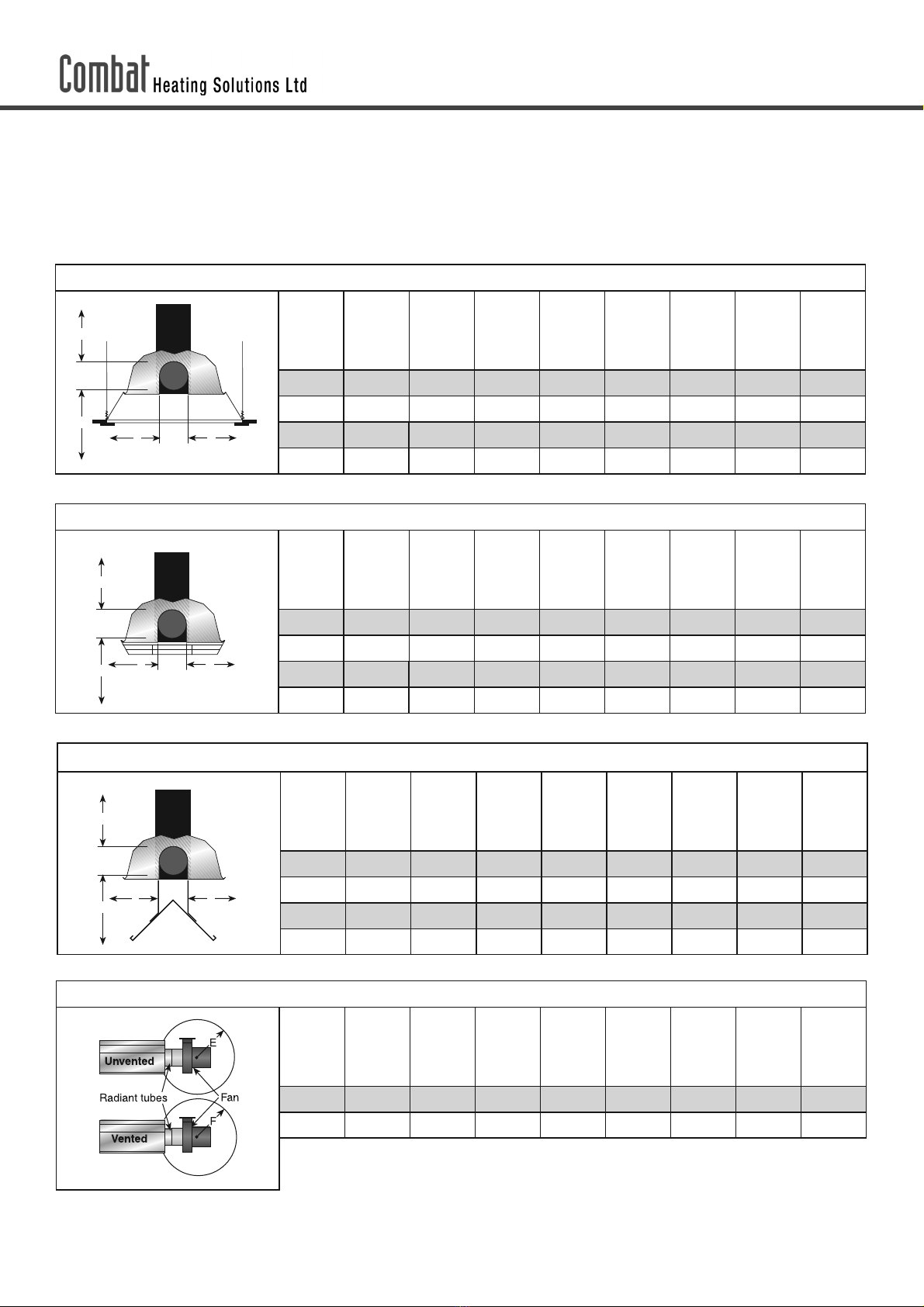
• To install the heater in accordance with the clearances
to combustibles.
• To furnish all needed materials not furnished as standard
equipment.
• To plan location of supports.
• To provide access to burners for servicing on all sides,
for burner removal.
• To provide the owner with a copy of the Installation,
Operation and Service manual.
• To never use heater as support for a ladder or any other
access equipment and never hang or suspend anything
from heater.
• To ensure there is adequate air circulation around the
heater and to supply air for combustion, ventilation and
distribution in accordance with all relevant regulations
and standards.
• To safely and adequately install heater using materials
with a minimal working load of 33kg.
• To ensure the heater is placed in an approved application.
2.1 Low Level User Instructions
In all situations, clearances to combustibles must be
maintained. Signs should be posted in storage areas to
specify the maximum stacking height of items placed below
heater to maintain required clearances to combustibles.
Minimum clearances must be maintained from vehicles
parked below the heater.
Caution should be used when running the system near
combustible materials such as wood, paper, rubber, etc.
Consideration should be given to partitions, storage racks,
hoists, building construction, etc.
A laminated wall tag is available for the heater as a permanent
reminder of the safety instructions and the importance of
the required clearances to combustibles. Please contact
Combat Heating Solutions Limited or your Combat Heating
Solutions Limited independent distributor to obtain the wall
tag. Affix the tag by peeling off the backing of the adhesive
strips on the rear surface and position the tag on a wall near
the heater (e.g. thermostat or Combat Heating Solutions
Limited Controller).
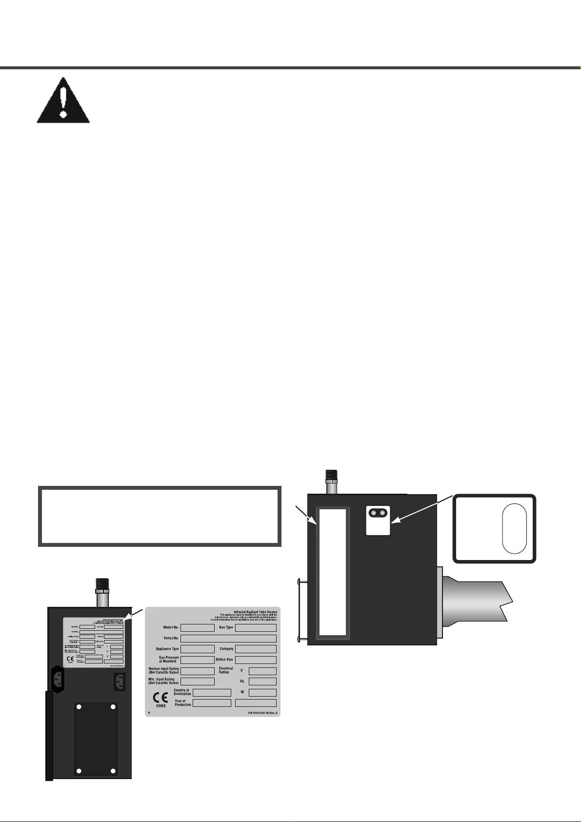
A copy of the wall tag (P/N 91037912) is illustrated on the
back cover. This copy of the wall tag can be affixed on the
wall near the heater. Know your model number and installed
configuration. Model number and installed configuration
are found on the burner and in the Installation, Operation
and Service Manual. Write the largest clearance dimensions
with permanent ink according to your model number and
configuration in the open spaces on the tag.
SECTION 2: INSTALLER RESPONSIBLILTY
Product Damage Hazard
Do not use heater in area containing corrosive
chemicals.
Refer to appropriate Material Safety Data
Sheets (MSDS).
Failure to follow these instructions can result
in product damage.
2.2 Corrosive Chemicals
CAUTION
Combat Heating Solutions Limited cannot be responsible
for ensuring that all appropriate safety measures are
undertaken prior to installation; this is entirely the
responsibility of the installer. It is essential that the contractor,
the sub-contractor or the owner identifies the presence of
combustible materials, corrosive chemicals or halogenated
hydrocarbons* anywhere in the premises.
*Halogenated Hydrocarbons are a family of chemical
compounds characterized by the presence of halogen
elements (fluorine, chlorine, bromine, etc.). These
compounds are frequently used in refrigerants, cleaning
agents, solvents, etc. If these compounds enter the air
supply of the burner, the lifespan of the heater components
will be greatly reduced. An outside air supply must be
provided to the burners whenever the presence of these
compounds is suspected. The warranty will be invalid if
the heater is exposed to halogenated hydrocarbons.
2.3 National Standards and Regulations
All appliances must be installed in accordance with the
latest revision of the applicable standards and regulations.
This refers also to the electric, gas and venting installation.
Note: Additional regulations for installations in public
garages, aircraft hangars, etc. may be applicable.

8Combat BH-COMPLETE Installation, Operation and Service
SECTION 3: CLEARANCES TO COMBUSTIBLES
Fire Hazard
Keep all flammable objects, liquids and
vapours the minimum required clearances to
combustibles away from heater.
Some objects will catch fire or explode when
placed close to heater.
Failure to follow these instructions can result
in death, injury or property damage.
• In locations used for the storage of combustible
materials, signs must be posted to specify the maximum
permissible stacking height to maintain required
clearances from the heater to the combustibles. Signs
must be posted adjacent to the heater thermostat. In
the absence of a thermostat, signs must be posted in a
conspicuous location.
• Consult local Building Inspectors, Insurance Providers
or other authorities for approval of proposed installation
when there is a possibility of exposure to combustible
airborne materials or vapours.
• Hang heater in accordance with the minimum
suspension requirements on Page 73, Section 18.7
through Section 18.9.
• If the radiant tubes must pass through the building
structure, be sure that adequate sleeving and fire stop is
installed to prevent scorching and/or fire hazard.
WARNING
WARNING
3.1 Required Clearances to Combustibles
Clearances are the required distances that combustible
objects must be away from the heater to prevent fire
hazards. Caution should be used when running the system
near combustibles. Combustibles are materials which may
catch on fire and include common items such as wood,
paper, rubber, fabric etc.
Maintain clearances to combustibles at all times for
safety.
Clearances for all heater models are located on Page 8
Figure 1 through Page 11, Figure 15 in this manual. Check
the clearances on each burner for the model heater being
installed to make sure the product is suitable for your
application and the clearances are maintained. Read and
follow the safety guidelines below:
• Keep petrol and other combustible materials
including flammable objects, liquids, dust or vapours
away from this heater or any other appliance.
• Do not spray aerosols in the vicinity of this
appliance.
• The stated clearances to combustibles represents
a surface temperature of 50°C above room
temperature. Building materials with a low heat
tolerance (such as plastics, vinyl siding, canvas,
tri-ply, etc.) may be subject to degradation at lower
temperatures. It is the installer’s responsibility to
assure that adjacent materials are protected from
degradation.
• Maintain clearances from heat sensitive equipment
and workstations.
• Maintain clearances from vehicles parked below
the heater.
• Maintain clearances from swinging and overhead
doors, overhead cranes, vehicle lifts, partitions,
storage racks, hoists, building construction etc.

9
FIGURE 1: LINEAR & DOUBLE LINEAR, HORIZONTAL MOUNTS
Model
BHCMP15ST
BHCMP30DL
BHCMP20ST
BHCMP40DL
BHCMP25ST
BHCMP50DL
BHCMP30ST
BHCMP60DL
BHCMP35ST
BHCMP70DL
BHCMP40ST
BHCMP45ST
BHCMP50ST
A150 150 150 150 150 150 200 200
B890 970 970 1020 1170 1220 1280 1330
C1570 1650 1650 1780 1930 1970 2010 2080
D890 970 970 1020 1170 1220 1280 1330
A
C
D
B
FIGURE 2: LINEAR & DOUBLE LINEAR, ONE SIDE REFLECTOR
Model
BHCMP15ST
BHCMP30DL
BHCMP20ST
BHCMP40DL
BHCMP25ST
BHCMP50DL
BHCMP30ST
BHCMP60DL
BHCMP35ST
BHCMP70DL
BHCMP40ST
BHCMP45ST
BHCMP50ST
A 150 150 150 150 150 150 200 200
B 230 230 230 230 230 230 230 230
C 1580 1760 1760 1930 2090 2130 2160 2240
D 1200 1380 1380 1500 1660 1710 1760 1860
A
C
D
B
FIGURE 3: LINEAR & DOUBLE LINEAR, TWO SIDE REFLECTORS
Model
BHCMP15ST
BHCMP30DL
BHCMP20ST
BHCMP40DL
BHCMP25ST
BHCMP50DL
BHCMP30ST
BHCMP60DL
BHCMP35ST
BHCMP70DL
BHCMP40ST
BHCMP45ST
BHCMP50ST
A 150 150 150 150 150 150 200 200
B 590 640 640 690 820 860 890 1020
C 1660 1810 1810 1960 2110 2160 2210 2320
D 590 640 640 690 820 860 890 1020
A
C
D
B
FIGURE 4: LINEAR & DOUBLE LINEAR, 45°MOUNT
Model
BHCMP15ST
BHCMP30DL
BHCMP20ST
BHCMP40DL
BHCMP25ST
BHCMP50DL
BHCMP30ST
BHCMP60DL
BHCMP35ST
BHCMP70DL
BHCMP40ST
BHCMP45ST
BHCMP50ST
A 200 200 200 250 250 275 300 300
B 200 200 200 200 200 200 200 200
C 1500 1660 1660 1860 1960 2030 2110 2160
D 1370 1520 1520 1630 1750 1820 1880 2000
A
C
D
B
3.2 Clearance Data- Linear and Double Linear
Note: 1. All dimensions are from the surfaces of all tubes, couplings, tees, elbows and crosses
2. Clearances B, C, and D can be reduced by 50% after 7500mm of tubing downstream from
the burner.
3. All measurements are in millimetres.
SECTION 3: CLEARANCES TO COMBUSTIBLES

10 Combat BH-COMPLETE Installation, Operation and Service
FIGURE 5: LINEAR & DOUBLE LINEAR, 2 FOOT DECO GRILLE
Model
BHCMP15ST
BHCMP30DL
BHCMP20ST
BHCMP40DL
BHCMP25ST
BHCMP50DL
BHCMP30ST
BHCMP60DL
BHCMP35ST
BHCMP70DL
BHCMP40ST
BHCMP45ST
BHCMP50ST
A 150 150 150 150 150 150 200 200
B 890 970 970 1020 1170 1220 1280 1330
C 1570 1650 1650 1780 1930 1970 2010 2080
D 890 970 970 1020 1170 1220 1280 1330
A
C
D
B
FIGURE 6: LINEAR & DOUBLE LINEAR, PROTECTIVE GRILLE
Model
BHCMP15ST
BHCMP30DL
BHCMP20ST
BHCMP40DL
BHCMP25ST
BHCMP50DL
BHCMP30ST
BHCMP60DL
BHCMP35ST
BHCMP70DL
BHCMP40ST
BHCMP45ST
BHCMP50ST
A 150 150 150 150 150 150 200 200
B 890 970 970 1020 1170 1220 1280 1330
C 1570 1650 1650 1780 1930 1970 2010 2080
D 890 970 970 1020 1170 1220 1280 1330
A
C
D
B
FIGURE 7: UNDERSHIELD
Model
BHCMP15ST
BHCMP30DL
BHCMP20ST
BHCMP40DL
BHCMP25ST
BHCMP50DL
BHCMP30ST
BHCMP60DL
BHCMP35ST
BHCMP70DL
BHCMP40ST
BHCMP45ST
BHCMP50ST
A 150 150 150 150 150 150 - -
B 990 1020 1270 1270 1370 1400 - -
C 840 965 1120 1120 1220 1270 - -
D 990 1020 1270 1270 1370 1400 - -
A
C
D
B
FIGURE 8: LINEAR & DOUBLE LINEAR, FLUED/FLUELESS CLEARANCE RADIUS REQUIREMENT FOR FLUE FAN
Model
BHCMP15ST
BHCMP30DL
BHCMP20ST
BHCMP40DL
BHCMP25ST
CMP50DLBH
BHCMP30ST
BHCMP60DL
BHCMP35ST
BHCMP70DL
BHCMP40ST
BHCMP45ST
BHCMP50ST
E 1000 1000 1000 1000 1000 1000 1000 1000
F 500 500 500 500 500 500 500 500
SECTION 3: CLEARANCES TO COMBUSTIBLES

11
FIGURE 9: U-TUBE, HORIZONTAL MOUNT
Model
BHCMP15UT
BHCMP20UT
BHCMP25UT
BHCMP30UT
BHCMP35UT
BHCMP40UT
BHCMP45UT
BHCMP50UT
A150 150 150 150 150 150 200 200
B890 970 970 1020 1170 1220 1270 1380
C1580 1730 1730 1910 1980 2050 2110 2210
D760 940 940 1000 1090 1150 1200 1300
A
C
D
B
FIGURE 10: U-TUBE, ONE SIDE REFLECTOR
Model
BHCMP15UT
BHCMP20UT
BHCMP25UT
BHCMP30UT
BHCMP35UT
BHCMP40UT
BHCMP45UT
BHCMP50UT
A 150 150 150 150 150 150 200 200
B 230 230 230 230 230 230 230 230
C 1580 1760 1760 1930 2090 2130 2160 2240
D 1200 1380 1380 1500 1660 1710 1760 1860
A
C
D
B
FIGURE 11: U-TUBE, TWO SIDE REFLECTORS
Model
BHCMP15UT
BHCMP20UT
BHCMP25UT
BHCMP30UT
BHCMP35UT
BHCMP40UT
BHCMP45UT
BHCMP50UT
A 150 150 150 150 150 150 200 200
B 590 640 640 690 820 860 890 1020
C 1660 1810 1810 1960 2110 2160 2210 2320
D 590 640 640 690 820 860 890 1020
A
C
D
B
FIGURE 12: U-TUBE, FULL 45°MOUNT
Model
BHCMP15UT
BHCMP20UT
BHCMP25UT
BHCMP30UT
BHCMP35UT
BHCMP40UT
BHCMP45UT
BHCMP50UT
A 200 200 200 200 200 200 200 200
B 200 200 200 200 200 200 200 200
C 1500 1650 1650 1860 1960 2040 2110 2160
D 1070 1170 1170 1320 1550 1620 1680 1780
B
C
D
A
3.3 Clearance Data- U Tube
Note: 1. All dimensions are from the surfaces of all tubes, couplings, tees, elbows and crosses
2. Clearances B, C, and D can be reduced by 50% after 7500mm of tubing downstream from
the burner.
3. All measurements are in millimetres.
4. Add 60 mm clearance to uncovered U-tube.
SECTION 3: CLEARANCES TO COMBUSTIBLES

12 Combat BH-COMPLETE Installation, Operation and Service
FIGURE 13: U-TUBE OPPOSITE 45°TILT
Model
BHCMP15UT
BHCMP20UT
BHCMP25UT
BHCMP30UT
BHCMP35UT
BHCMP40UT
BHCMP45UT
BHCMP50UT
A200 200 200 250 250 275 300 300
B1370 1530 1530 1630 1780 1830 1880 1930
C1500 1650 1650 1860 1960 2040 2110 2160
D560 560 560 560 560 560 560 560
A
C
D
B
FIGURE 14: U-TUBE, PROTECTIVE GRILLE
Model
BHCMP15UT
BHCMP20UT
BHCMP25UT
BHCMP30UT
BHCMP35UT
BHCMP40UT
BHCMP45UT
BHCMP50UT
A 150 150 150 150 150 150 200 200
B 890 970 970 1020 1170 1220 1270 1380
C 1580 1730 1730 1910 1980 2050 2110 2210
D 760 940 940 1000 1090 1150 1200 1300
A
C
D
B
FIGURE 15: U-TUBE, FLUED/FLUELESS CLEARANCE RADIUS REQUIREMENT FOR FLUE FAN
Model
BHCMP15UT
BHCMP20UT
BHCMP25UT
BHCMP30UT
BHCMP35UT
BHCMP40UT
BHCMP45UT
BHCMP50UT
E 1000 1000 1000 1000 1000 1000 1000 1000
F 500 500 500 500 500 500 500 500
'MVFMFTT
'MVFE
SECTION 3: CLEARANCES TO COMBUSTIBLES

13
SECTION 4: MAJOR COMPONENT DESCRIPTIONS
Burner (shown with Tube Gasket)
Must be installed with the flame
observation window facing down.
Aluminium
Reflector
Alternate
overlap as
shown on
overview.
Minimum
overlap is
160mm.
Burner Tube
Supplied in 3,000mm lengths.
Burner tube is always the first
tube after the burner.
Tube
Heat treated aluminised tube
supplied in 3,000 lengths.
Fan Tube with Internal Swirler
Supplied in 3,000 lengths. Fan tube
is always the last tube on the heater
where the fan is attached.
Tube and Reflector Hanger with
Clamp Package
Position this hanger no more
than 100mm away from the
burner assembly.
Coupling Assembly with Lock
Reflector End Cap
Punch out centre section to
accommodate tube.
Tube and Reflector Hanger
Suspend system from these
hangers.
Reflector Support Strap, Wire
Form & #8 x 3/4 (3.9 x 19mm)
Screw
Fan Assembly (Includes Flange)
Fan assembly is attached to the last
section of heat exchanger tubing (Fan
Tube).
Flex Gas Line
(Not part of heater kit, unless
ordered separately)
Damper Flange Assembly
For use on Multi-burner Systems.
(only part of heater kit when ordered as
a multi-burner)
Fan Flange Assembly and Screws
Tee Assembly
Bow Shackle
Spring Hook
(Not part of a heater kit
unless ordered separately)
U-Tube Support Bracket
U-Tube
Height Adjuster
(Only as part of a
double linear heater
kit)

14 Combat BH-COMPLETE Installation, Operation and Service
Severe Injury Hazard
Secure burner to burner tube with nuts and
lock-washers.
Hang heater with materials with a minimum
working load of 75 lbs (33 kg).
Failure to follow these instructions can result in
death, injury or property damage.
SECTION 5: GENERAL SUSPENSION DETAILS
WARNING
To ensure your safety, and comply with the terms of the warranty, all units must be installed in accordance with these
instructions.
The gas or the electrical supply lines must not be used to support the heater.
Do not locate the gas or electric supply lines directly over the path of the flue products of the heater.
The heater must be installed in a location that it is readily accessible for servicing.
The heater must be installed in accordance with clearances to combustibles as indicated in this manual.
The minimum and maximum gas inlet pressures must be maintained as indicated on the rating plate.
Typical installation configurations are shown on Page 14, Figure 16.
Suspension chain is not supplied as standard equipment.
Cut/Pinch Hazard
Wear protective gear during installation,
operation and service.
Edges are sharp.
Failure to follow these instructions can result in
injury.
WARNING

15
Figure 16: Critical Hanger Placement
Description Part Number
Burner Tube 03051600
Bow Shackle E0007576
Tube/Reflector Hanger 03090100
For suspension angles other than shown, additional chain supports may be required.
NOTE: Only connections to the heater hanger using a bow shackle would be supplied with a heater kit. Chain could
also be supplied if required & would be a separate item to the heater kit therefore would be shown listed separately
on any quote or order.
Typical Suspension Details
I-beam
Beam Clamp
Concrete Beam
Screw Hook
min. 10mm
I-beam
10mm
Rod
600mm
minimum*
Turnbuckle
(not included)
300 mm
minimum*
Bow shackle
Anchor Locknut
Washer
Wood Beam
* Allows for thermal expansion of system
Side View
100mm max.
Hanger
Bow shackle
Hanger
Front View 45° Angle
SECTION 5: GENERAL SUSPENSION DETAILS

16 Combat BH-COMPLETE Installation, Operation and Service
SECTION 6: LINEAR & DOUBLE LINEAR HEATER INSTALLATION
Cut/Pinch Hazard
Wear protective gear during installation,
operation and service.
Edges are sharp.
Failure to follow these instructions can result
in injury.
The figures in this section provide a general overview of
component placement in a Linear and Double Linear system.
The location of some components such as supports and
couplings is crucial for proper installation. Assemble the
heater components as shown on Page 16, Figure 17.
For optional reflector configurations for linear heaters see
Page 8, Figure 1 through Page 9, Figure 8.
Install appropriate suspension hardware, beam clamps,
chain or rod at predetermined locations. Adjustments of
chain length will provide uniform pitch.
If any step is unclear, please contact Combat Heating
Solutions Limited at +44 (0) 121 506 7700.
Part No. Description
BHCMP15ST
BHCMP20ST
BHCMP25ST
BHCMP30ST
BHCMP35ST
BHCMP40ST
BHCMP45ST
BHCMP50ST
0730XXXX Burner Assembly (Input and Fuel varies) 1 1 1 11111
07260001 Fan Package XP1 1 1 1 1 - - - -
07260002 Fan Package XP2 - - - - 1 1 1 -
07260003 Fan Package XP3 - - -----1
07260004 Linear Package 1 1 1 11111
03051100 Burner Tube, 100mm x 3048mm 1 1 1 11111
91409408 Tube 100mm x 3048mm - 1 1 22233
S5127W Fan Tube 100 x 3048mm with 3048mm Swirler - 1 1 11111
S5134W Fan Tube 100mm x 3048mm with 2134mm Swirler 1 - ------
1329600 Standard Coupling Assembly 1 2 2 33344
1329700 Coupling Lock 1 2 2 33344
02750303 Reflector Aluminium 2439mm 3 4 4 66677
02750800 Tube End Cap Aluminium 2 2 2 22222
03090100 Tube and Reflector Hanger 3 4 4 55566
01318901 Tube Clamp Package (Including Nut, Washer & Bolt) 1 1 1 11111
91908004 Wire Form 2 3 3 55566
94320812 Screw #8 x ¾ (3.9mm x 19mm) (goes with 03050000) 4 6 6 10 10 10 12 12
03050000 Reflector Support Strap 2 3 3 55566
E0007576 Bow Shackle 3 4 4 55566
91107720 U-Clip Package (20 Pieces) 1 1 1 11111
S7199K Damper Flange Assembly (For use on Multiburner Systems) 1 PER HEATER
WARNING
6.1 Linear Standard Parts List

17
Figure 17: Linear General Assembly Overview
Coupling
Tube Clamp
Package
Reflector
Burner Tube
Weld Spot
Tube and Reflector Hanger
Reflector Support
Fan Tube
Internal Swirler
Fan Assembly
(for Single Heaters)
Damper Assembly
(required for Multi-
burner)
U-Clips
Reflector
End Cap
Burner
SECTION 6: LINEAR & DOUBLE LINEAR HEATER INSTALLATION

18 Combat BH-COMPLETE Installation, Operation and Service
#)$.1%-
#)$.120'/
#)$.125'/
#)$.130'/
#)$.135'/
#)$.140'/
#)$.145'/
#)$.150'/
Figure 18: Linear Layout Overview
LEGEND
Burner
Reflector
Tube
Tube/Reflector
Hanger
Coupling
Assembly
Fan
Assembly
Damper
Assembly
a Reflector width (not shown) 508 mm
b End cap to burner/fan 50 mm
c End cap to hanger 50 mm
d Distance to first hanger 2290 mm
e Distance typical between hangers 3050 mm
f Burner height 366 mm
g Burner length 291 mm
Model BHCMP15ST BHCMP20ST BHCMP25ST BHCMP30ST BHCMP35ST BHCMP40ST BHCMP45ST BHCMP50ST
Reflector Overlap
(approx.) 700mm 250mm 250mm 530mm 530mm 530mm 330mm 330mm
SECTION 6: LINEAR & DOUBLE LINEAR HEATER INSTALLATION

19
PART NUMBER DESCRIPTION
BHCMP30DL
BHCMP40DL
BHCMP50DL
BHCMP60DL
BHCMP70DL
0730XXXX Burner Assembly (Input and Fuel Varies) 22222
07260002 Fan Package XP2 -----
07260003 Fan Package XP3 11111
07260004 Linear Package 22222
03051600 Burner Tube, 100mm x 3048mm 22222
91409408 Tube, 100mm x 3048mm - 2244
S5127W Fan Tube, 100mm x 3048mm, with 3048 mm Swirler - 2222
S5134W Fan Tube, 100mm x 3048mm, with 2134 mm Swirler 2 ----
01330203 Tee, 100 mm x 100mm x 100mm 11111
01329600 Standard Coupling Assembly 46688
01329700 Coupling Lock 46688
02750303 Reflector, Aluminium, 2439mm 6 8 8 12 12
02750800 Reflector End Cap, Aluminium 44444
03090100 Tube and Reflector hanger 6 8 8 10 10
01318901 Tube Clamp Package (including Nut, Washer & Bolt) 22222
91908004 Wire Form 4 6 6 10 10
03050000 Reflector Support Strap 4 6 6 10 10
E0007576 Bow Shackle 6 8 8 10 10
91107720 U-Clip Package (20 Pieces) 22222
E0007582 Height Adjuster 6 8 8 10 10
94320812 Screw #8 x 3/4 (3.9mm x 19mm),(goes with 03050002) 8 12 12 20 20
6.2 Double Linear Standard Parts List
SECTION 6: LINEAR & DOUBLE LINEAR HEATER INSTALLATION

20 Combat BH-COMPLETE Installation, Operation and Service
Reflector
End Cap
Burner
Reflector
Fan Assembly
Tube Clamp
Package
Burner Tube
Reflector Support
Tube and Reflector Hanger
Internal Swirler
Weld Spot
Fan Tube
Coupling
Tube Clamp Package
U-clips
Figure 19: Double Linear General Assembly Overview
SECTION 6: LINEAR & DOUBLE LINEAR HEATER INSTALLATION
This manual suits for next models
21
Table of contents
Other COMBAT Heater manuals