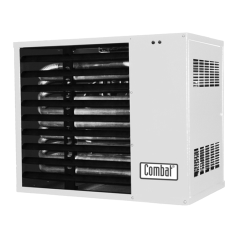
COMBAT ECO20A User manual

1code HG0140.00GB-M ed.A-1507
ECO
Operating, Installation and Maintenance Manual
CONDENSING WARM AIR HEATER ECO
GB
This manual cannot be copied in part or in full for disclosure to third parties without the prior written consent by Combat HVAC Limited

2
code HG0140.00GB-M ed.A-1507 ECO
WARM AIR HEATER ECO
Declaration of Conformity
COMBAT HVAC LIMITED
Unit A, Kings Hill Business Park
Darlaston Road, Wednesbury
West Midlands, WS10 7SH UK
Telephone: 0121 506 7700
Fax: 0121 506 7701
www.combat.co.uk
With this document we declare that the unit:
Model: Warm air heater ECO, ECOxxEA, ECOxxB, ECOxxBE
has been designed and manufactured in compliance with the prescriptions of the following EC Directives:
Machinery Directive 2006/42/CE
Gas Appliance Directive 2009/142/CE (ex 90/396/CE)
Electromagnetic Compatibility Directive 2004/108/CE or 2014/30/UE
Low Voltage Directive 2006/95/CE or 2014/35/UE
If the unit is to be installed into an equipment (combined), the manufacturer disclaims any responsibility if this
equipment is not previously declared compliant with the requirements specied in IIB Enclosure of the above said
Machinery Directive.
COMBAT HVAC LIMITED
CODE SERIAL NUMBER

3code HG0140.00GB-M ed.A-1507
ECO
WARM AIR HEATER ECO

4
code HG0140.00GB-M ed.A-1507 ECO
WARM AIR HEATER ECO

5code HG0140.00GB-M ed.A-1507
ECO
WARM AIR HEATER ECO
INDEX
SECTION 1. GENERAL CAUTIONS ................................................................... 6
SECTION 2. SAFETY INSTRUCTIONS ............................................................. 6
2.1 Fuel ...............................................................................................
6
2.2 Gas Leaks...................................................................................... 6
2.3 Power Supply................................................................................. 7
2.4 Operation ......................................................................................
7
2.5 Maintenance .................................................................................. 7
2.6 Transport and Handling ................................................................. 7
2.7 Packaging ...................................................................................... 7
SECTION 3. TECHNICAL FEATURES ............................................................... 8
3.1 Technical Data ............................................................................... 9
3.2 Dimensions .................................................................................... 10
SECTION 4. USER'S INSTRUCTIONS .............................................................. 12
4.1 Operating Cycle ............................................................................. 12
4.2 Accessories ................................................................................... 12
4.3 Interface Panel............................................................................... 14
4.4 Reset ............................................................................................. 15
4.5 Set-up ........................................................................................... 16
SECTION 5. INSTALLATION INSTRUCTIONS................................................... 17
5.1 General Installation Instructions .................................................... 17
5.2 Installation...................................................................................... 17
5.3 Condensation Drainage ................................................................. 19
5.4 Connections to the Flue................................................................. 20
5.5 Electrical Connections ................................................................... 26
5.6 Modulation PCB Parameters ......................................................... 28
5.7 Analysis of lockouts - Faults ......................................................... 31
SECTION 6. GAS CONNECTION ....................................................................... 33
SECTION 7. SERVICING INSTRUCTIONS......................................................... 34
7.1 Country Table - Gas Category ...................................................... 34
7.2 Gas Settings Table......................................................................... 35
7.3 ConguringwithLCDDisplay ........................................................ 38
7.4 Startingupforthersttime............................................................ 39
7.5 Analysis of combustion .................................................................. 39
7.6 Conversion to LPG ........................................................................ 40
7.7 Conversion to gas G25 - G25.1..................................................... 41
7.8 Conversion to gas G2.350............................................................. 41
7.9 Replacing the gas valve................................................................. 42
7.10 Replacing STB and NTC ............................................................... 42
7.11 Replacing the modulation PCB...................................................... 42
SECTION 8. MAINTENANCE.............................................................................. 43
SECTION 9. WIRING DIAGRAMS ...................................................................... 44
SECTION 10. LIST OF SPARE PARTS................................................................. 45
10.1 Parts for the electrical panel .......................................................... 45
10.2 Parts for the burner unit ................................................................. 46

6
code HG0140.00GB-M ed.A-1507 ECO
WARM AIR HEATER ECO
1. GENERAL CAUTIONS
This manual is an integral part of the product and must always
accompany it.
Should the equipment be sold or passed on to someone else,
always make sure that this manual is supplied with the equip-
ment for future reference by the new owner and/or installer.
The manufacturer shall not be held civilly or criminally respon-
sible for injuries to people or animals or damages to things
caused by incorrect installation, calibration and maintenance
or by failure to follow the instructions contained in this manual
orbyoperationscarriedoutbyunqualiedstaff.
This product must be used only for the applications for which
it was designed or approved. Any other use must be regarded
as hazardous.
During the installation, operation and maintenance of the equip-
ment described in this manual, the user must always strictly
follow the instructions given in all the chapters of this operating
and maintenance manual.
----------------------------------------------------------------------------------
The warm air heater must be installed in compliance with
current regulations, according to the manufacturer's instruc-
tions and by suitably qualied staff. who has the technical
knowledge in the heating sector.
----------------------------------------------------------------------------------
Conversion between different types of gas and maintenance
operations must be carried out before being switched on, and
only by suitably qualified staff. Technical Service Centres
certified by current and older standards.
For more information, visit our Web site
www.combat.co.uk or contact the manufacturer directly.
The warranty conditions for this equipment can be found in the
Combat HVAC Limited Terms and Conditions Of Sale
Reference standards (only applies to Italy):
• Ministerial Decree No. 74 of 12/04/96;
• Ministerial Decree No. 37 of 22/01/2008;
•UNI-CIG 7129-1, -2, -3, -4 standard, which regulates the
installationofnaturalgasredequipment;
•UNI-CIG 7131 standard, which regulates the installation
ofLPGredequipment;
•Law No. 10/91 and Presidential Decree No. 412/93 on
reducing energy consumption;
• Legislative Decree 192/05 of 19/08/2005;
• Legislative Decree 311 of 29/12/2006;
•UNI CIG 11528:2014 standard "Design, installation and
commissioning gas systems with heat output higher than
35 kW".
These standards may be subject to changes and/or additions.
2. SAFETY INSTRUCTIONS
This chapter describes the safety instructions to be
followed by the installer.
2.1. Fuel
Before starting up the heater, make sure that:
• the gas mains supply data is compatible with the data
stated on the dataplate
•thecombustionairintakeducts(whenfitted)andtheflue
exhaustpipesarethosespecifiedbythemanufacturer;
• the combustion air is supplied in such a way as to avoid
even partial obstructions of the intake grille (caused by
leavesetc.);
• the fuel intake internal and external seal is checked during
the testing stage, as required by applicable standards;
• the heater is supplied with the same type of fuel it has
been designed for;
•the system is correctly sized for such flow rate and is
fitted with all safety and monitoring devices required by
applicable standards;
• the inside of the gas pipes and air distribution ducts for
ducted heaters has been thoroughly cleaned;
•thefuelflowrateissuitableforthepowerrequiredbythe
heater;
•thefuelsupplypressureisbetweenthe rangespecified
on the dataplate.
2.2. Gas Leaks
If you smell gas:
• do not operate electrical switches, telephones or any other
object or device that could produce sparks;
•immediatelyopendoorsandwindowstocreateanairflow
to vent the gas out of the room;
• close the gas valves;
•Contact your gas provider

7code HG0140.00GB-M ed.A-1507
ECO
WARM AIR HEATER ECO
If the equipment is not used for long periods, shut the gas sup-
ply off through the gas shut off valve and disconnect it from
the power supply.
If the heater is to be put out of service, in addition to the above
operations, potential sources of hazard on the unit must be
removed.
It is strictly forbidden to obstruct the Venturi pipe inlet, located
on the burner-fan unit, with your hands or with any other objects.
Anyobstructioncouldcauseabackrefromthepremixedburner.
2.6. Transport and Handling
The heater is delivered fastened to a pallet and covered with a
suitably secured cardboard box.
Unload the heater from the truck and move it to the site of
installation by using means of transport suitable for the shape
of the load and for the weight.
If the unit is stored at the customer’s premises, make sure a
suitable place is selected, sheltered from rain and from excessive
humidity, for the shortest possible time.
Any lifting and transport operations must be carried out by
skilled staff, adequately trained and knowledgeable on the
working procedures and safety regulations.
Once the equipment is moved to the correct position, the un-
packing operation can be started.
2.7. Packaging
The unpacking operation must be carried out by using suitable
tools or safety devices where required. Recovered packaging
materials must be separated and disposed of according to ap-
plicable regulations in the country of use. While unpacking the
unit, check that the unit and all its parts have not been damaged
during transport and match the order. If damage has occurred
or parts are found to be missing, immediately contact the sup-
plier. The manufacturer is not liable for any damages occurred
during transport, handling or unloading.
2.3. Power supply
The equipment must be correctly connected to an effective
earthing system, made in compliance with current regulations
(CEI64-8,onlyappliestoItaly).
Cautions
• Check the effectiveness of the earthing system and, if
required,calloutaqualifiedengineer.
• Check that the mains power supply is the same as the
power input stated on the equipment dataplate and in
this manual.
• Do not swap the neutral with the live wire.
•Theelectricalsystemand,morespecifically,thecablesec-
tion, must be suitable for the equipment maximum power
input , shown on the dataplate and in this manual.
Do not pull electric cables and keep them away from heat sources.
---------------------------------------------------------------------------------
NOTE: It is compulsory to install, upstream of the power
cable, a fused multi-pole switch with contact opening wider
than 3mm.
The switch must be visible, accessible and less than 3m
away from the control board.
All electrical operations (installation and maintenance)
must be carried out by suitably qualied staff.
---------------------------------------------------------------------------------
2.4. Operation
Do not allow children or inexperienced people to use any electri-
cally powered equipment.
The following instructions must be followed:
•do not touch the equipment with wet or damp parts of your
body and/or with bare feet;
•do not leave the equipment exposed to the elements (rain,
sunetc....)unlessitisadequatelyprotected;
• do not use the gas pipes to earth electrical equipment;
• do not touch the hot parts of the heater, such as the flue
gas exhaust duct;
•donotwettheheaterwithwaterorotherfluids;
• do not place any object over the equipment;
• do not touch the moving parts of the heater:
2.5. Maintenance
---------------------------------------------------------------------------------
Maintenance operations and combustion inspections must
be carried out in compliance with current standards.
---------------------------------------------------------------------------------
Before carrying out any cleaning and maintenance operations,
isolate the heater from the mains power supply via the switch
located on the electrical system and/or on the shut-off devices.
If the heater is faulty and/or incorrectly operating, switch it off
and do not attempt to repair it yourself, but contact the local
Technical Service Centre.
All repairs must be carried out by using genuine spare parts.
Failure to comply with the above instructions could compromise
the safety of the equipment and invalidate the warranty.

8
code HG0140.00GB-M ed.A-1507 ECO
WARM AIR HEATER ECO
DONOTCOVER IT WITHYOUR HAND OROTHEROBJECTS!
WARNING: Before switching on the heater, open the lou-
vres by at least 45°
HG0140.00_IM_001
3. TECHNICAL FEATURES
The ECO series modulating warm air heaters have been de-
signed for industrial and commercial environments.
The heater PCB continually modulates the heat output between
the minimum and maximum power, according to heating re-
quirements.
The premixing and modulating technology allows the heater to
achieveefciencyabove108%oftheL.C.V.
The heater can operate independently; it can be started up by
simply connecting it to the power mains and to the gas mains.
The heaters' heat output ranges from 5 to 97kW.
The units can be controlled:
• from an external time/temperature control;
• externally with the modbus (through SmartControl, Smart.
netorSmart.web);
• proportionally, with a 0-10 Vdc external control.
The heat exchanger complies with the manufacturing require-
ments for condensing warm air heaters, and with standards
EN1020 and EN1196.
The combustion chamber and the surfaces of components where
condensation occurs (such as the pipe bundle and exhaust
hood),aremadeofAISI441,inordertoprovidehighresistance
to condensation and temperature.
The following table illustrates the types of stainless steels used:
USA-AIS EN-No. COMPOSITION
AISI 441 1.4509 X2 CrTiNb 18
The innovative design and the large heat exchanging surface
of the combustion chamber and of the tubes ensure optimum
efciencyanddurability.
The burner is made entirely of stainless steel with special me-
chanical solutions to ensure optimal reliability and performance
levels, as well as high thermal and mechanical resistance.
The control located on the front panel allows the service centre
to check and view the working phases and identify any faults
that may have occurred.
Inherent Safety
The performance increase at minimum power is achieved by
using a sophisticated air/gas mixing technique and by adjusting
at the same time the combustion air and the fuel gas.
This technology increases the heater safety as the gas valve
suppliesthefuelaccordingtotheairow.Unlikewithatmos-
pheric burners, the CO2proportion remains constant throughout
theheateroperatingrange,allowingittoincreaseitsefciency
when the heat output reduces.
If there is no combustion air, the valve will not supply gas; if
thecombustionairowreduces,thevalvewillautomatically
reducethegasowyetwillkeepits combustionparameters
at optimal levels.
Low emissions
The premixed burner, in combination with the air/gas valve,
ensures "clean" efcient combustion with low emissions of
pollutants.

9code HG0140.00GB-M ed.A-1507
ECO
WARM AIR HEATER ECO
Model: ECO20A ECO34A ECO45A ECO65A ECO80A ECO105A
Type of equipment B23P - B53P - C13 - C43 - C53 - C63
ECcertication PIN. 0476CQ0451
NOx Class Val 5
Heater Performance
min max min max min max min max min max min max
Burnerheatoutput(Hi) kW 4.75 19.00 7.60 34.85 8.50 42.00 12.40 65.00 16.40 82.00 21.00 100.00
Useful heat output kW 4.97 18.18 8.13 33.56 8.97 40.45 13.40 62.93 17.77 80.03 22.77 97.15
EfciencyHi(NetC.V.) % 104.63 95.68 106.97 96.30 105.50 96.30 108.06 96.82 108.35 97.60 108.40 97.15
EfciencyHs(GrossC.V.) % 94.26 86.20 96.37 86.76 95.07 86.76 97.36 87.22 97.62 87.93 97.68 87.52
Fluelosseswithburneron(Hi) % 0.4 4.3 0.6 3.7 0.5 3.7 0.2 3.2 0.3 2.4 0.2 2.8
Fluelosseswithburneroff(Hi) % <0.1 <0.1 <0.1 <0.1 <0.1 <0.1
Losses in enclosure (1) 0% 0% 0% 0% 0% 0%
Max. condensation (2) l/h 0.4 0.9 1.1 2.1 3.3 2.7
Flue gas emissions
Carbonmonoxide-CO-(0%ofO2)(3) ppm < 5 < 5 < 5 < 5 < 5 < 5
Nitrogenoxides-NOx-(0%ofO2)(4) 38 mg/kWh -
22 ppm
42 mg/kWh -
24 ppm
33 mg/kWh -
19 ppm
39 mg/kWh -
22 ppm
32 mg/kWh -
18 ppm
41 mg/kWh -
23 ppm
Availablepressureatue Pa 80 90 100 120 120 120
FLUE GAS temperature, CO2contentandmaximumfluegasflowrate:seegastablesonpage37andonthe
fol-lowing pages
Electrical Data
Power supply V 230 Vac - 50 Hz single-phase
Power input W 147 180 270 310 280 310 425 510 500 613 650 750
Power input in stand-by W <5
Ingress Protection Rating IP IP 20
Operating Temperatures °C from -15°C a +40°C - for lower temperature, a burner housing heating kit is required
Storage Temperatures °C from -25°C to +60°C
Connections
Ø gas connection (5) GAS UNI/ISO 228/1-
G 3/4"
UNI/ISO 228/1-
G 3/4"
UNI/ISO 228/1-
G 3/4"
UNI/ISO 228/1-
G 3/4"
UNI/ISO 228/1-
G 3/4" (6)
UNI/ISO 228/1-
G 3/4" (6)
Ø Combustion air intake/exhaust pipes mm 80/80 80/80 80/80 80/80 100/100 (7) 100/100 (7)
Air ow rate
Airowrate m3/h 2700 4300 4500 7800 9000 11100
Air temperature increase °C 5.28 19.30 5.42 22.37 5.73 25.74 4.92 23.13 5.66 25.49 5.89 25.09
Number and diameter of fans 1 x Ø350 1 x Ø 450 1 x Ø450 2 x Ø400 2 x Ø450 3 x Ø400
Fans speed rpm 1370 1370 1370 1370 1370 1370
Soundpowerlevel(Lw)(8) dB(A)
Weight
Net weight kg 70 77 98 125 143
Weight when packaged kg 85
NOTES:
(1)Thelossesfromtheenclosuremustberegardedaszeroastheheaterisinstalledinaheatedenvironment.
(2) Max..condensationproducedacquiredfromtestingat30%Qn.
(3) Valuereferencedtocat.H(G20)
(4) WeightedvaluetoEN1020ref.toclassH(G20),referredtoHi(L.C.V.).
(5)Thegaslinemustbemeasuredbytakingintoaccountthelengthofthepipesandnottheheaterdiameter.
For countries requiring an ISO connection different from the one shown above, an adaptor will be supplied.
(6) FortheECO80AandECO105Amodels,theminimumgassupplyductdiametermustbeUNI/ISO 228/1- G 1".
(7) Ø100/100obtainedbyusingadaptorssuppliedasstandard.
(8) Measuredatadistanceof5mfromthemachine.
3.1. Technical Data

10
code HG0140.00GB-M ed.A-1507 ECO
WARM AIR HEATER ECO
Mod.
ECO
Overall dimensions Inlet Shelf Supply GAS Packaging
B H L HB LB IS ID ØG GO GV Bi Li Hi Hbi
ECO20A
500
690
795
520
490 395 400
3/4''
180 255
810 890 850 123
ECO34A
985 680 490 495
810 1080 850 123
ECO45A
765 595
810 1080 920 123
ECO65A 1310 1010 655 660 810 1410 920 123
ECO80A
845
1515
675
1180 770 745
210 275
810 1610 1040 123
ECO105A 1740 1410 895 845 810 1810 1040 123
Bi
Li
Hbi
Hi
145
HG0140.00_C2_001
HG0140.00_C2_001
HG0140.00_C2_001
HG0140.00_C2_001
IS ID
HB
L
108
LB
62
H
730
515
B
125
TO
A
S
F
AO
A
GV
GO
TVAV
S
F
G
HG0130.00 A 041
3.2. Dimensions

11 code HG0140.00GB-M ed.A-1507
ECO
WARM AIR HEATER ECO
Mod.
ECO Horizontal exhausts (STD)
A F AV TV S
ECO20A
80 80
430
120 155
ECO34A
ECO45A
505
ECO65A
ECO80A
100* 100* 560 140 185
ECO105A
* Obtained by using the adaptors supplied as standard.
Mod.
ECO
Vertical drains (OPT.)
A F AO TO S
ECO20A
80 80
145
120 155
ECO34A
ECO45A
ECO65A
ECO80A
100* 100* 140 185
ECO105A
* Obtained by using adaptors supplied as standard.
145
HG0140.00_C2_001
HG0140.00_C2_001
HG0140.00_C2_001
HG0140.00_C2_001
IS ID
HB
L
108
LB
62
H
730
515
B
125
TO
A
S
F
AO
A
GV
GO
TV AV
S
F
G

12
code HG0140.00GB-M ed.A-1507 ECO
WARM AIR HEATER ECO
Cable colour:
1. Brown
2. Black
3. Blue
4. Grey
CN08
ID4IDC2ID3
ID2
HG0140.00_IIM_037
4. USER'S INSTRUCTIONS
4.1. Operating Cycle
The wall mounted ECO heaters operation is fully automatic; they
are equipped with electronic equipment with self check facility
that manages all the burner control and monitoring operations
and with a microprocessor based electronic PCB that controls
the heat output regulation.
The heat demand depends on the PCN parameter d0 of the
heater electronic PCB:
• d0=2: input ID2-IDC2 closed and NTC1<TH1;
• d0=5: input ID2-IDC2 closed and input 0-10Vdc>Von;
•d0=7: input ID2-IDC2 closed and control from Modbus ON.
The ignition request occurs when the following conditions are met:
• when the heater is powered on and is not in a lockout
condition;
•when the contact is closed on terminals ID2/IDC2 of the
heater PCB.
When these conditions are met, the burner fan will be immedi-
atelystarted;whenthepre purging-timehasexpired,theflame
willbelitwithanignitionpowerofapproximately50%ofthe
maximumpower.Oncetheamestabilisingtimehasexpired,
the burner will start to modulate its heat output according to the
supply air temperature.
If there is no ameduringtheignitionstage,theequipment
makes4ignitionattempts;if,atthefthattempt,ignitionisstill
unsuccessful, the heater will be locked out.
The heater will be switched on when the ID2/IDC2 contact opens
on the terminal box; disconnecting the power supply is prohibited,
except for emergencies because, if the heater is switched
off, the flue gas extractor fan will continue to work for
approximately 90 seconds to clean up the combustion
chamber (combustion chamberpost-cleaningphase).
Failure to perform the post-cooling operations on the exchanger
will:
•reduce the life of the exchanger and invalidate the warranty;
•cause the safety thermostat to operate and require a
manual reset.
If, during the cooling cycle, there is a new demand for heat, the
modulation PCB will wait for the cooling fans to shut down and
then reset the counters to start a new cycle.
Parameter d6 of the modulation PCB, which can be programmed
from 0 to 256 seconds, controls the minimum interval between
the time the equipment is switched off and restarted.
----------------------------------------------------------------------------------
IMPORTANT: P owering off the machine before completing
the cooling cycle and with machine set to ON is strictly
prohibited. Failure to follow these instructions shall in-
validate the warranty and cause early deterioration of the
heat exchanger.
-----------------------------------------------------------------------------------
4.2. Accessories
TheECO heaters are ttedas standard with amultifunction
LCD panel located on the front panel, which is used to control,
congureanddiagnosetheequipmentparameters.
This panel cannot be remotely controlled.
Ambient temperature control
The ECO heaters are supplied without remote control and/
or room thermostat as they can operate with different remote
controls, some of which are supplied as accessories, whilst
others are commercially available.
Operating modes:
•A time and temperature thermostat control such as
the Combat HVAC NRG Control, with a clean contact to
be connected to the PCB ID2/IDC2 terminals;
• SmartControl code G20800IT;
• program SMART.NET G16900-USB.
Instructions on how to install and operate the accessories
can be found in manuals supplied with the accessories.

13 code HG0140.00GB-M ed.A-1507
ECO
WARM AIR HEATER ECO
Operation with a SmartControl chronothermostat
G20800IT
The control operates as a chronothermostat and can be used
as a monitoring device for a single zone system at the same
temperature, where up to 32 heaters can be installed simultane-
ously, controlled by a single control.
Being a single zone system, only one ambient temperature and
one calendar can be set for the entire zone being monitored.
The chronothermostat is equipped with a very bright, easy to
read LED display, where all the parameters of the connected
heaters can be read and set up; it also allows users to control
the heaters auto or manual mode, to check the burner opera-
tion, to plan a weekly, annual calendar and to control the daily
time ranges.
For operating instructions and installation diagrams, please see
the SmartControl control manual HG0080IT "SMARTCON-
TROL CHRONOTHERMOSTAT Operating, Installation and
Programming Manual".
Safety thermostats
ECOheatersarettedwithasafetythermostatwithautomatic
reset and positive safety setting. A safety operation of this ther-
mostat occurs when its sensitive component is broken.
Whenthethermostatisoperated,throughtheamemonitor-
ingequipment, the burner stopsandtheameequipmentis
locked out.
Thelockoutoftheameequipment,causedbythesafetyther-
mostat operation, is indicated on the LCD display of the CPU
PCB on the machine with F20.
Thelockoutisclassiedas"non-volatile"andrequiresamanual
reset.
Near the safety thermostat, there is an NTC1 probe set to the
value of the ST1 parameter, which reduces the burner's heat
output when the set point is reached, regardless of other input
signals..Theprobemonitorstheheatoutput/coolingairowratio.
It is not advisable to change the ST1 value without consulting
the Service Centre.
Ambient temperature setting
Connectingaroomthermostat(chronothermostat)oranON/
OFF switch is compulsory.
If a thermostat supplied by third parties is installed, the ambient
temperature must be programmed on the thermostat.
In this type of installation, we recommend that a G15100 re-
mote control is used to allow users to check the reasons for the
lockout and, if necessary, to remotely reset it without accessing
the heater.
Lockouts Fxx
The modulation PCB can identify more than 30 different types
of faults. This ensures accurate diagnostics.
Codes and possible causes of lockouts are listed later the manual.
For more serious lockouts, requiring a manual reset, the arrows
on the LCD display on board of the machine must be simulta-
neously pressed or the reset can be remotely carried out with
the controls provided.
SmartControl

14
code HG0140.00GB-M ed.A-1507 ECO
WARM AIR HEATER ECO
4.3. Interface Panel
TheECO heaters are ttedas standard with amultifunction
LCD panel located on the front panel of the suspended heater,
whichisusedtocontrol,congureanddiagnosealloperating
parameters of the equipment.
Thepanelisttedwithared3digitLCDdisplayandwithfour
functionkeys:↑,↓,ESCandENTER;thedisplayallowsthe
user to display the heater operating mode and its Faults.
It allows the service centre to change the main operating pa-
rameters.
Changing parameters requires a password.
Viewing the machine status
The machine status is shown on the display by the following
wordings:
rdy the machine is on without burner flame,
it is waiting for the ON control and/or the heat demand
from the thermostat;
On themachineisonwithburnerameorisintheignition
phase;
OFF the machine is turned off by the control on the LCD.
Any heat demands will be ignored.
To light the burner, the LCD must show the wording
"heater ON";
Fxx Fault detected.
During normal operation, the display will show the wording On
if the burner is on; rdy when the heater is being switched off or
the room temperature has been reached.
Air the EST operation has been selected under the
FUN menu; set FUN to ON or OFF;
Axx ECO heater address;
If the heater has an address other than Ø, the display
will show, alternating it with the operation in progress,
the address assigned to the heater.
In the event of communication problems between the CPU-
SMART PCB and the LCD panel, the word CPUwillashon
thedisplayiftheproblemiscausedbytheCPU;threeashing
dots will be displayed if the problem is caused by the display
PCB. If needs be, check that the display and the PCB are cor-
rectly connected and that the small cable RJ11 is securely held
in the connector.
Navigating the menu
Themenuhasthreelevels.Therstisvisiblewithout
enteringa password, the second and third require entering
second and third level passwords.
If the ECO heater is connected to a Smart Control or to the
SMART.NET, and therefore with an address different from Ø,
parameterscanonlybeviewedandcannotbemodied.Some
menus are not available.
The Service Centre that is required to use all menus must fol-
low these instructions:
• disconnect the power supply;
• set the PCB address to Ø;
• restore power;
•after nishing the work, please remember to reset the
switches to the previously set position.
Usethearrowstoscrollthemenus:↑(uparrow)and↓(down
arrow).PressENTERtoselectthemenu,andagaintoselectthe
parameter.Changetheparameterwiththearrowsandconrm
the change by pressing ENTER.
To exit the parameter or menu, press ESC. If you exit the pro-
gramming function, after about 10 minutes the program will exit
the menu and go back to the "machine status" display.
Tochangetheparameter,pressthearrowkeys:pressing↑(up
arrow)increasestheparameterby1,pressing↓(downarrow)
reduces it by 1. When the arrow keys are pressed for at least
three seconds, the parameter scrolling speed is increased.
Toconrmachangeinparameters,pressENTERforatleast3
seconds. A change in the parameter is indicate by the display
ashing.
All submenus can be scrolled from the bottom to the top, and
they start over when the end of the menu is reached.
First level menus
Thefollowingmenusareavailableontherstlevel:
machine status provides information about its operation
(ex.rdy,ON,etc.);
ON,OFF);
FUN from FUN it is possible to select the function
ON,OFForEST(donotselectEST);
REG this menu allows the user to force the burner
to the minimum or the maximum for
combustion tests; it automatically returns to
the previous position at the end of the preset
time(10minutes);
TIN allows the user to read the value of the 0/10
Vdcsignal(ifpresent)comingintotheheater;
Pra not used;
ABI used to enter the PWD to access second and
third level menus.
Entering the password 001 will provide access to the second
level and make the Set Point, I/O, Parameters and Fault menus
available.
Entering the password
•Fromtheinitialscreen(ON/OFF/rdy/FXX)usethe↑
(arrow up)and↓(arrowdown)keystoreachtheABI
function;hold down the ENTER key for 3 seconds;
•SetthepasswordinsidetheABIandmenuconfirmitwith
ENTER; hold it down for approximately 3 seconds (the
flashingdisplaywillconfirmthattheparameterhasbeen
stored);
•PressESCand,byusingthe↑and↓arrowkeys,return
totheinitialscreen(ON/OFF/rdy/FXX);pressENTERfor
3 seconds;
•Usethe↑and↓arrowkeystoreachthedesiredmenu
item (Flt,I/O,SET,PAR);
• Press ENTER to access the function;
•Usethe↑and↓arrowkeystoselecttheparametersto
be displayed and edited;
• Press ENTER to display the parameter value;
•Usethe↑and↓arrowkeystoeditthevalue(onlySET
andPAR);
•PressENTERtoconfirmthechangemade;
•To exit the parameter and the menu, press ESC until the
initialscreenisdisplayed(ON/OFF/rdy/FXX).

15 code HG0140.00GB-M ed.A-1507
ECO
WARM AIR HEATER ECO
Second and third level menus
The second and third level menus are reserved to the Service
Centre and can be accessed only by entering a password,
which can be requested for the manufacturer's Service Centre.
For more detail, see Paragraph 7.3 "Programming with a LCD
panel".
Fault list
In the event of a lockout, the heater PCB will display a code,
which indicates what problem has occurred.
To reset the heater, simultaneously simply press the LCD panel
arrow keys for at least 3 seconds or operate one of the remote
controls provided.
TheFaultsareclassifiedaccordingtothetypeoferror;themost
common and easier to sort out by user are:
F1x these faults are caused by the burner failed ignition;
they all require a manual reset.
F20 heater safety thermostat lockout; this fault must be
manually reset.
F21 jumper missing between terminals ID1 and IDC1 or
rebreakerconnectedtoterminalsID2andIDC2tripped.
F3x
F4x
lockouts caused by faults of the flue gas extractor.
lockouts caused by an error or by a missing temperature
probe; they must be sorted out by the Service Centre.
F51 the temperature of the air supplied has exceeded the
upper limit set in parameter TH1; as the temperature drops, the
lockout will sort itself out; manual reset is not required.
F60 on the LCD panel only, the heater is connected to a
SmartControl or to SMART.NET but does not communicate.
When communication is restored, the lockout condition will
disappear; manual reset is not required.
The list and meanings of all faults are shown in the FAULT table
in Paragraph 5.7 "Analysis of Lockouts - Faults".
4.4. Reset
The modulation PCB allows the operator to identify more than
thirty different causes of lockouts. This makes it possible to
manage each event very accurately.
To reset the lockouts, press both arrows simultaneously for a
few seconds.
Lockouts may be remotely controlled by using:
• the digital input ID4-IDC4 - button N.O.;
• the Smart Control - optional;
• the ModBus protocol.
Ifignitionfails,theamemonitoringsystemreattemptsignition
four times. After four failed attempts, it will lock out and will
display the code F10.
The lockout codes and their cause is shown in the FAULT table
in Paragraph 5.7 "Analysis of Lockouts - Faults".
Iftheamemonitoringequipmenthaslockedout(codesfrom
F10toF20),itcanberesetitbyusingthebuttonontheequip-
ment itself. This lockout is shown by a LED that lights up on
the equipment.
----------------------------------------------------------------------------------
WARNING : The ame monitoring equipment memorises
the number of manual resets that are performed during its
lifetime. In case of ve resets performed in a period of 15
minutes, without a ame being ignited and detected, the
equipment will go into a "timed" lockout (F13). In this case,
it is required to wait another 15 minutes before resetting
it again.
Press the reset button on the equipment to immediately
reset this lockout condition.
----------------------------------------------------------------------------------
NOTE: SHOULD THE SAFETY THERMOSTAT (STB) OPEN
BEFORE STARTING THE START-UPCYCLE (THIS COULD BE
CAUSED, FOR EXAMPLE, BY LOW TEMPERATURES), THE
PILOT LIGHT EQUIPMENT WILL BE KEPT IN "STAND-BY"
AND FAULT F15 WILL BE SHOWN AFTER 300 SECONDS.
---------------------------------------------------------------------------------

16
code HG0140.00GB-M ed.A-1507 ECO
WARM AIR HEATER ECO
4.5. Set-up
The ECO heaters have three heat output regulation modes:
• 0/-10 Vdc
• ModBus
• NTC1 temperature probe.
To correctly set the control parameters, a d0 parameter must
beprogrammed,whichidentiesthetypeofcontrolassociated
with the heater.
Function Equipment Heater
Flame modulation
d0=2 NTC1
d0=5 0-10Vdc
d0=7 Modbus – H71
Operation with chronothermostat
The heater operation is entirely automatic and, by using a
chronothermostat, the ambient temperatures can be regulated.
The chronothermostat and the PCB monitor all the control and
regulation functions, whilst the safety functions are performed by
theflamemonitoringequipmentandbythesafetythermostats.
Operation with SMART CONTROL
The heater controls can be operated remotely from the Smart
Control panel (OPTIONALcode G20800IT), which uses the
ModBus protocol and can control up to 32 heaters.
To use the Smart Control as a temperature control, simply change
the d0 parameter on each heater with a default value of 2 set
fortheNTC1,bysettingitto7(ModBuscontrol).
The Smart Control can be used to supervise/display and monitor
(activepartoftheregulation).
AtemperatureprobeisfittedinsidetheSmartControl;aremote
temperature regulation probe can be added.
The remote probe can be programmed as the main probe or it
can be added to the internal probe to obtain an average value
between the two measurements.
When the Smart Control is also used to control the temperature,
you must:
•index the heater modules from 1 to 32 by entering the ad-
dress of each module through the dip switch;
•connect a NTC temperature probe to the Smart Control
(usetheinternalprobe);
•set the control parameters both on the PCB and the Smart
Control.
The remote NTC temperature probe which can be connected
mustbea10KΩ,β3435type.
The probe must be connected to the NTC/NTC terminals and
can be located locally or elsewhere, according to the settings
required.
----------------------------------------------------------------------------------
NOTE: The remote NTC temperature probe is an optional
external probe (code G07202); not to be mistaken for the
modulation probe NTC1.
---------------------------------------------------------------------------------
The Smart Control is powered by a 24 Vdc voltage.
To enable the demand for heat, close the Smart Control I1 input
(makeajumperbetweenterminalsV+andI1).
The Smart Control displays the following information: burner
on/off, percentage of modulation, alarms and resets.
The Smart Control requires you to:
•specifyiftheprobeisexternal(remote),internalorboth;
•changethenumberofslaves(connectedheaters)accord-
ing to requirements:
• set the ON-OFF or PID settings;
•settheheatingmode(operation:"heating")andthedesired
set point value, locally or remotely.
• set the time ranges.
For more information on how to to remotely operate the con-
trols with the Smart Control, please refer to the HG0080.00IT
"SMARTCONTROL CHRONOTHERMOSTAT MANUAL. Op-
erating, Installation and Programming Manual".
The Smart Control, through its PID regulation, calculates the
modulation percentage and compares the calculated value
against the operation percentage of each module: The modula-
tion percentage sent to the modules is always the same. When
the set point is exceeded, the heaters will be switched off.
SmartControl

17 code HG0140.00GB-M ed.A-1507
ECO
WARM AIR HEATER ECO
5. INSTALLATION INSTRUCTIONS
Instructions for installing and setting the heater are intended
forsuitablyqualifiedpersonnelonly.
5.1. General Installation Instructions
Where allowed, the heater can be installed directly in the room
to be heated.
To install the heaters inside the rooms, different regulations
and requirements must be complied with according to the
type of fuel used and to the country of destination.
In fact, the installer must strictly comply with applicable stand-
ards and regulations in the country where the machine will be
installed and therefore set up.
Ventilation
Room Sealed Installation
when installed as a room sealed heater, the air for
combustion is drawn in from outside the building. It is
important to ensure that there is adequate ventilation to
provide air for the fan/s.
Heaters Installed Within The Heated Space.
Where the volume of the heated space is greater than
4.7M3 per kilowatt of total rated heat input and the air
change rate is at least 0.5/h, additional high and low level
ventilation will not be required.
For a building having an air change rate less than 0.5/h,
ventilation will e necessary in accordance with the local
and national codes. Ventilation direct to outside must be
provide as follows:
Heaters up to 70 Kw heat input: 5.0cm2 per Kw of rated
input.
Building Ventilation
Where ventilation is required, air must be taken from an
outside point where it is not likely to be contaminated or
obstructed.
where natural ventilation is used, suitable ventilation wit
outside air at low level must be provided in accordance
with the above section and local and national codes.
Where mechanical ventilation is used, extract rate must
be 5%-10% less than the inlet rate. The mechanical
ventilation must be interlocked with the burner on the
heater.
-a)
MINIMUM DISTANCES TO BE OBSERVED
Condensation drain
The heater is supplied completed with a water trap to drain
the condensation. The water trap is an integral part of the
heater and is regarded as a safety component; therefore,
replacing it with a different type, not approved by the heater's
manufacturer is prohibited.
The condensation must be drained in compliance with standards
applicable in the country where the heater is installed.
5.2. Installation
Theminimumheightanddistancesfromthewallsandtheoor
are available for the installation.
The codes for the available shelves are:
G27900 Fixed shelf kit for ECO20A-65A;
G27820 Rotating shelf kit for ECO20A;
G27830 Rotating shelf kit for ECO34A-45A;
G27850 Rotating shelf kit for ECO65A-80A;
G27870 Rotating shelf kit for ECO105A.
when installing the heater
are shown in the following
drawing.
The minimum distances
are the distances required
to carry out maintenance
operations and are stated in
mm; the height of 2500mm
is the minimum height re-
quired by the standard for
"suspended" machines.
Two types of supporting
shelves,xedandrotating,

18
code HG0140.00GB-M ed.A-1507 ECO
WARM AIR HEATER ECO
HG140.00_IM_030
HG140.00_IM_039
Suspended heater
ECO20A-80A HEATERS: To install a suspended heater by
using eyebolts, tie rods or chains, a kit containing supporting
pins is available, as an accessory; its code is: G27880. This kit
is suitable for all ECO models and does not include eyebolts
(optionalaccessorycodeX00728).
HG140.00_IM_006
Fixed shelves
Toinstallthexedshelvestothewalls:
•fixittothewallandlevelthebracketwithaspiritlevel:
---------------------------------------------------------------------------------
NOTE: make sure that the screws and wall plugs are suitably
sized for the type of wall and that they can withstand the heater
weight.
-----------------------------------------------------------------------------------
•Place the suspended heater by centering it on the
brackets in order to match the holes on the heater with
the holes on the brackets, taking into account that, for
all models, thetipsofthebracketsareflushwiththeedge
ofthe suspended heater;
•Usethepapertemplate suppliedto mark the holes tofixthe
bracketstothewall;
•Fix the heater in position by using the M8 supplied as
standard, inserting locking washer between the screw
and the bracket.
code HG0140.00GB-M ed.A-1507
HG140.00_IM_041
PLATE TO TIE THE
HEATER TO PILLAR
cod. G27835
Rotating shelves
Theinstructions on how tot the rotating shelfand a paper
template to position the shelf onto the wall can be found inside
the shelf packaging.
Using rotating shelves is recommended in the following cases:
a) whenttingtheheaterontoacorner;
b) whenttingtheshelfontoapole;
c)whenttingtheheateratarightanglewiththewallitisxedto.

19 code HG0140.00GB-M ed.A-1507
ECO
WARM AIR HEATER ECO
Trap
Condensation
discharge hole
Condensation detection electrode
HG140.00_IM_011
HG140.00_IM_015
HG140.00_IM_038
DETAIL A:
Condensation disharge hole
A
5.3. Condensation Drainage
Special attention must be paid to the condensate drain; an
incorrectly installed drain, in fact, could jeopardize the correct
operation of the equipment.
The factors to be taken into account are:
• risk of condensation build-up inside the heat exchanger:
• risk of condensation water freezing in the pipes;
• risk of fumes discharged from the condensate drain.
Build up of condensation in the heat exchanger
During normal operation, condensate must not be allowed to
accumulate within the heat exchanger.
AsensorttedtheECOheaterinternalwatertrapchecksand
stops the burner from operating before the condensate reaches
a potentially dangerous level inside the flue gas collection
hood. When installing the heater, special attention must be
paid to make sure it is perfectly level in order to maintain the
typical inclination of the tube bundle.
Connection to the condensate drain
The ECO heaters are supplied with the condensation drain in
the bottom section of the heater.
It is the installers responsibility to ensure that the condensate
is discharged in accordance with the local and national
authorities regulations in force
•
Precautions
Materials to be used for the condensation drainage system:
• aluminium, stainless steel, silicone or Viton pipe.
• for cold pipes, carrying water only, PVC pipes.
Do not use copper or galvanised iron pipes.
Protection from frost
The condensation drainage system must be suitably protected
to prevent the condensation in the circuit from freezing.
We recommend that the condensation collection system is lo-
cated inside heated rooms. If the system is located outdoors, the
pipe, after the water trap, must have an open type connection
to make sure that any ice formed inside the external system
does not prevent the condensation from being drained away.
In any case, it is recommend that the longest pipe should be laid
inside the heated room, for example by collecting the condensa-
tionushtotheoorwiththedownpipelocatedinsidetheroom.
Free drainage
If the unit is installed outdoors, unless the temperatures never
drops below freezing, the condense could be drained directly
outside, without any connections to other pipes. It is essential
to check thatthecondensateflowsawayfromtheunit.
If the drain needs to be connected to pipes, an open type con-
nection(socketpipe),similartotheone illustrated in picture
below must be installed to prevent ice forming in the pipe from
blocked condensate drain, and the ensuing build-up of conden-
sate in the heat exchanger.
If the drain pipe is installed in an outdoor site, it may need to
be insulated and/or heated by means of a heating cable.
Drainage into water courses
Taking the condensation drain inside the room to be heated is a
good solution in order to avoid the formation of ice; condensa-
tion can be drained into water courses or can be collected and
treated with alkaline solutions.
Neutralising the condensation
The condensation produced by the combustion of natural gas
has an acidity of 3.5-3.8 PH.
Onrequest,Combatcansupplythekit(G14303)requiredto
neutralise the condensation; the kit consists of:
•a plastic tank for the collection of condensation (measuring
BxHxL30x18x20cm);
• calcium carbonate.
For more information, contact the Service Centre.
----------------------------------------------------------------------------------
WARNING: Not all countries allow the types of condensa-
tion drains described here. Please refer to the requirements
specied by local legislation.
----------------------------------------------------------------------------------

20
code HG0140.00GB-M ed.A-1507 ECO
WARM AIR HEATER ECO
5.4. Connections to the Flue
TheECOheatersarettedwithawatertightcombustioncircuit
and with a fan located upstream of the heat exchanger.
Connectiontotheue,accordingtowheretheheaterisinstalled,
can be made as "C" type, with combustion air being drawn from
outside, or as "B" type with combustion air being drawn from
the heater installation site.
Morespecically,theheateriscertiedforthefollowingexhausts:
C13-C33-C53-C63-B23.
Certifiedpipesandterminalsmustbeused.
The air intake terminals and flue exhausts must prevent ac-
cess to a ball with a diameter higher than or equal to 12 mm.
COMBAT sells certied i ntake o r e xhaust t erminals that
must therefore be bought together with the heaters.
TheECOheatersaresuppliedasstandardwithhorizontalfit-
tings,flueandairintake,locatedinthebackoftheheater.Itis
possible, even during the installation stage, to move the flue
exhaustandairintakettingstothetopoftheheater;thisis
usefulwhentheexhaustisttedtotheroof.
On request, and according to the quantity, the heater can be
providedwithfittingsinthetopsectiontofitaverticalexhaust.
To make the flue exhaust, taking into account that the ECO
heaters are of a condensing type, the following material must
be used.
•Aluminium with a thickness higher than or equal to 1.5 mm;
•- stainless steel with a thickness of at least 0.6 mm; the
steelmusthaveacarboncontentofatleast0.2%.
Pipesfittedwithasealmustbeusedinordertopreventtheflue
gases leaking from the pipes; the seal must be suitable to
withstand flue temperatures ranging between 25°C and 210°C for
ECO heaters.
----------------------------------------------------------------------------------
WARNING: Using plastic materials on flue exhaust ducting
is strictly prohibited.
----------------------------------------------------------------------------------
For ECO heaters, the flue does not need to be insulated to
prevent the formation of condensation in the pipe, as this will
notaffecttheheater,whichisfittedwithawatertrap.
----------------------------------------------------------------------------------
IMPORTANT: The horizontal sections of flue must be in-
stalled with a slightly incline (1°- 3°) towards the heater, in
order to prevent the build up of condensation in the exhaust.
---
Protect the pipe with a guard if required to protect the flue
from accidental contact.
For the air intake, use:
• Aluminium with a thickness of at least 1.0 mm;
• Stainless steel with a thickness of at least 0.4 mm;
Selection Guide
The table showing the flue exhaust system calculation data
can be found in Paragraph 7.2 "Gas settings data table". The
maximumrecirculationpercentageis11%.
The tables below show the pressure drop for Ø 80 and Ø 100
terminals and exhaust ducting.
If the terminal is not directly connected to the heater and,
therefore, extra routing is required, according to the length of
the ducting, the diameter of the selected terminals, extensions
and bends must be checked.
After establishing the routing, the pressure drop must be calcu-
lated for each component by referring to the tables below accord-
ing to the ECO heater used; each component has a different
pressuredropvalueasthegluegasesowrateisdifferent.
Add together the pressure drops of the single components,
checking that the result is not higher than the available value
for the heater to be used. If a combustion air supply pipe is
fitted,thepressurelossesmustbeaddedtotheflueexhaust
pressure drop
If the sum of pressure drop is higher than the pressure avail-
able, ducting with higher diameter must be used, rechecking the
calculation; a pressure drop higher than the pressure available
at the flue exhaust reduces the heater module heat output.
----------------------------------------------------------------------------------
NOTE: If the module is installed indoor:
• using coaxial connections is allowed for heaters for a pipe
length not exceeding 3 metres;
• the flue exhaust terminal must be installed in compliance
with reference national regulation requirements.
----------------------------------------------------------------------------------
NOTE: The following pictures show examples of flue exhaust
and air intake that can be created by using the kits available
from the catalogue; the table shows the pipe maximum lengths
between the heater and the terminal. If the duct routing requires
the use of bends, the length required must be subtracted from
the available length:
Bend Ø 80 90° EqL1.65 m
Bend Ø 80 45° EqL0.80 m
Bend Ø 100 90° EqL0.2.30 m
Bend Ø 100 45° EqL0.1.03 m
* Valid equivalent lengths for wide radius bends.
----------------------------------------------------------------------------------
This manual suits for next models
5
Table of contents
Other COMBAT Heater manuals
Popular Heater manuals by other brands

Kermi
Kermi Fedon User and installation instructions

Scarlett
Scarlett SC-151 instruction manual

Gabarron
Gabarron ADL 5030/14 Installation instructions and user guide

Vigor Equipment
Vigor Equipment V4891-1.0 operating instructions

White&Brown
White&Brown ALPATEC RCMB 21 manual

HAEGER
HAEGER Mini Oil User instructions

Bimar
Bimar HC504&.CH Instruction booklet

ETL
ETL MUA Controls Installation, operation and maintenance manual

Aktobis
Aktobis WDH-IFH20 manual

Brant Radiant Heaters
Brant Radiant Heaters LD Series Operation, installation, maintenance and parts manual

Costway
Costway EP25437 Instruction booklet

Amazon
Amazon B0753PHV8Z manual