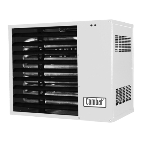
COMBAT FRSA Manual

Room Sealed Unit Heaters
Installation, Commissioning,
Service & User Instructions
Models
FRSA, FRSB,
FRSC & FRSD
75 - 210
August 2000
Part No. X224B


Page 1
ROOM SEALED UNIT HEATERS
These appliances have been tested and certified as complying with the essential
requirements of the Gas Appliance directive, The low voltage directive ,The
Electromagnetic Compatibility Directive and the Machinery Directive for use on natural
gas and L.P.G gas when installed , commissioned and maintained in accordance with
these instructions.
These instructions refer to appliances designed to operate in the following countries...
Ireland (IE), Spain (ES), Italy (IT) & United Kingdom (GB)
Appliances designed for other countries are available on request.
These appliances are Cat II 2 H 3+ appliances for use with natural gas (G20) or L.P.G.
(G31 / G30) as stated on the heater data plate, and are intended for indoor installation
only.
For GB and IE They are type C32 appliances for vertical flue terminals and
type C 12 for horizontal flue terminals.
For use in ES and IT they are Type C32 appliances for connecting to suitable
approved sealed combustion air and flue systems.
This Appliance must be installed in accordance with the rules in force and used only
in a sufficiently ventilated space, as specified in these instructions.
Before installation, check that the local distribution conditions, nature of gas and
pressure, and adjustment of the appliance are compatible.

Page 2
ROOM SEALED UNIT HEATERS
Contents
The parts of this manual are numbered by section, clause and sub clause. Hence 1:2:3 refers to section I
clause 2 sub clause 3. Figure numbers also follow this notation. Hence Fig. 2:3 is section 2 Fig. 3.
Section
1. General Specification
2. Technical Data
3. Heater Installation
4. Commissioning of the Air Heater
5. Wiring Diagram
6. Servicing Instructions
7. Removal and Replacement of Parts
8. Fault Finding Charts
9. User Instructions
10. Conversion between Natural gas and L.P.G.
11. Parts List
12. Commissioning Data Sheet
THIS AIR HEATER IS FOR USE WITH NATURAL GAS OR L.P.G. AS STATED ON THE HEATER DATA
PLATE
THESE INSTRUCTIONS ARE TO BE LEFT WITH THE USER OR NEAR THE HEATER
NOTE
: Every effort is made to ensure the information within this manual is accurate. However, Roberts-Gordon
reserves the right to alter specifications without prior notice.
Roberts-Gordon shall not be liable to rectify any defects or damage caused by any modifications made or
attempted to be made to the heating units by the customer, his servants, agents or employees.
WARRANTY The Heat Exchanger has a ten year Warranty (subject to terms and conditions).

Page 3
ROOM SEALED UNIT HEATERS
Section 1. General Specification
1.1 Basic Information
COMBAT® FRSA, FRSB, FRSC & FRSD ranges of unit air heaters are type C32 appliances for vertical flue
terminals and C12 for horizontal flue terminals both of which have room sealed combustion and fan assisted
flues. They are designed to be suspended or shelf mounted, and are produced in an 8 size range from 27 kW
(92,124 Btu/hr) to 76 kW (259,312 Btu/hr) heat input (Gross CV).
Heaters must be installed in accordance with local regulations and the requirements of Section 3 of these
Instructions.
A permanent electrical supply of 230 volts 50 Hz, single phase is required for all models and all models must
be earthed.
ON/OFF, temperature and time control may be obtained by use of CC1/A control consoles (obtainable from
Roberts-Gordon.) or by the use of individual controls as per the circuit diagrams in Section 5.
The FRSA range of heaters are fitted with quiet running axial fans.
The FRSB range of heaters are fitted with Direct Drive centrifugal fan blowers to allow them to be fitted to
duct distribution systems ,when supplied with the factory fitted outlet spigot.
The FRSC range of heaters are the same specification as the FRSB range, but are fitted with an enclosure for
the main fans to allow inlet ducting to be fitted.
The FRSD range are sold without a fan unit to be installed onto the customers ducting and air moving system.
1.2 Heater Operation
COMBAT® FRSA, FRSB, FRSC & FRSD warm air heaters are supplied ready for installation on site. They
are fitted with an automatic ignition control which ignites the gas and monitors for the safe operation of the
burner each time the external controls call for the heater to operate.
When the external controls call for heat, the automatic control operates the flue fan and burner, to supply heat
to the heat exchanger. After approximately 2 or 3 minutes the air delivery fan will start to run, supplying warm
air to the building.
When the external controls are satisfied they will turn off the burner leaving the fan running to cool down the
heat exchanger. When cool enough the fan thermostat will turn off the fan.

Page 4
ROOM SEALED UNIT HEATERS
Fig. 1.1 General Arrangement - FRSA Models
WARNING:
The main electrical isolator should only be used in an emergency and should not be used for
closing down the burner, as this switches off the main fan prematurely and may damage the
heat exchanger.
Such action may cause a fire hazard and invalidate the warranty .
Mounting Brackets
Flue Pipe (front) Air Intake Pipe (rear) Gas Pipe Connection
Outlet Grille with
Adjustable Louvres
Main Fan
on Rear
Panel
Lock for
door
Electrical entry
and Second
Limit Stat on
Rear
Lockout Reset Button
Lighting Instructions
Warning Lights:
GREEN - Burner On
RED - Lockout
Data Plate
Dimension Data (see Figs.1.2 to 1.4 - Dimension Diagrams)
Model
'A' - Width
'B' - Width between hanging points
'C' - Flue/Air Intake Diameter
'D'
'E'
'F'
'G' - Inlet/Outlet Duct Spigot Width
Weight - FRSA
Weight - FRSB
Weight - FRSC
Weight - FRSD
95
775
296
100
140
192
117
508
113
118
136
105
105
775
296
100
140
192
117
508
115
129
147
115
120
915
436
100
140
192
117
648
128
140
159
128
135
915
436
130
225
168
132
648
138
152
171
138
150
1055
576
130
225
168
132
788
150
163
184
150
170
1055
576
130
225
168
132
788
154
178
199
154
210
1195
716
130
225
168
132
928
174
200
223
174
75
705
226
100
140
192
117
438
105
110
127
97
mm
mm
mm
mm
mm
mm
mm
kg
kg
kg
kg

Page 5
ROOM SEALED UNIT HEATERS
Fig. 1.2 Front View Dimension
All FRS Models*
Fig.1.3 Plan View
All FRS Models (Shown without main fan)
Fig.1.4 Side View Dimensions
FRSC
* Note:
FRSD models are fitted with an air outlet spigot as standard. All inlet and outlet duct spigots are complete with 25mm mez. flange.
140 510 (Centres)
751 680
1431
674 x G (Width)
234
FRSD
495 x G
(Width)
234
495 x G
(Width)
234
751
1051
150 150
140 510 (Centres)
140 510 Centres
751
837
FRSA FRSB
140 510 Centres
751
1211 (except Models 150 & 170: 1177)
240 240B Centres
A
990
Gas Connection
C (Air Intake)
C (Flue)
52
55
103
Rear
E
D
FFront
Hanging Points

Page 6
ROOM SEALED UNIT HEATERS
Note:
for FRSD ducted units sold without fans, the air flow provided by the system must be able to produce at least the lower of the air flows of the FRSA or the FRSB heater
of the same model.
Technical Data - General Data for all FRS... Range
TABLE 2.1 GENERAL DATA
LEDOM5759501021531051071012
SEVLAVSAGNIAM
EPYT&REBMUN
avoN.T.I.S
711.228.0
FFO1
avoN.T.I.S
711.228.0
FFO1
avoN.T.I.S
711.228.0
FFO1
avoN.T.I.S
711.228.0
FFO1
avoN.T.I.S
711.228.0
FFO1
avoN.T.I.S
711.228.0
FFO1
avoN.T.I.S
711.228.0
FFO1
avoN.T.I.S
711.228.0
FFO1
EZISNOITCENNOCSAG 4/3R4/3R4/3R4/3R4/3R4/3R4/3R4/3R
EPYTNAFEULF NIROT
61467OUA
NIROT
61467OUA
NIROT
61467OUA
NIROT
61467OUA
NIROT
61467OUA
NIROT
52157OUA
NIROT
52157OUA
NIROT
52157OUA
.qsmmEZISECIFIROEULF 05.4305.0407.1405.4402.8400.649445
NAFLAIXA-SLIATEDNAF
)sttaW(DAOLLACIRTCLELATOT 352352092092605605644644
ROTOMNAFNIAM v032w071v032w071v032W012v032W012v032W081v032W081v032w071x2v032w071x2
)spmA(TNERRUCGNINNURROTOM 07.007.068.068.08.18.145.145.1
TNERRUCTRATSROTOM 09.109.103.203.24.34.32.42.4
EPYTNAFNIAM
&
DETTIFREBMUN
GMPnafiS
101-14053
1
GMPnafiS
101-14053
1
GMPnafiS
101-14093
1
GMPnafiS
101-14093
1
GMPnafiS
101-14024
1
GMPnafiS
101-14024
1
GMPnafiS
101-14053
2
GMPnafiS
101-14053
2
FµEZISROTICAPAC 5.25.2 3355 5.2x25.2x2
rh/³mWOLFRIA
)nim/³tf(
0323
)1091(
0323
)1091(
0063
)9112(
0063
)9112(
0663
)4512(
0093
)5922(
0654
)4862(
0046
)7673(
)a(BdRNm3TAGNITARESION 060600.1600.16461600.5600.46
NAFLAGUFIRTNEC-SLIATEDNAF
sttaWDAOLLACIRTCELELATOT 24624624624624624629112911
ROTOMNAFNIAM v032W055x1v032W055x1v032W055x1v032W055x1v032W055x1v032W055x2v032W055x2v032W055x2
TNERRUCGNINNURROTOM 9.32.52.51.51.55.74.93.01
TNERRUCTRATSROTOM 8.44.64.60.60.63.96.118.21
NAFNIAM
dettiFrebmuN
deepsteslamroN
072-072NIROT
1
woL
072-072NIROT
1
muideM
072-072NIROT
1
muideM
072-072NIROT
1
muideM
072-072NIROT
1
muideM
142-142NIROT
2
woL
142-142NIROT
2
woL
072-072NIROT
2
muideM
rh/³mWOLFRIA
)nim/³tf(
0062
)0351(
0013
)5281(
0023
)3881(
0523
)0191(
0623
)9191(
0844
)7362(
0075
)5533(
0026
)9463(
deepshgihtasmumixaM
spmAtnerruCnuR
spmAtnerruCtratS
1.6
8
9.6
6.8
9.6
6.8
1.5
7
1.5
7
4.11
6.31
4.11
6.31
pmA7.31
1.71
)a(BdRNm3TAGNITARESION 00.7500.3600.3600.7602.5600.8600.6600.07
Section 2. Technical Data

Page 7
ROOM SEALED UNIT HEATERS
L.P.G. II2H 3+
II2 H 3+ G20 H GAS
TABLE 2.2 BURNER DATA
LEDOM5759501021531051071012
VCSSORGTUPNITAEH Wk
rh/utB
72
42129
43
800611
5.83
263131
00.44
821051
05.94
498861
5.45
459581
5.16
838902
00.67
213952
VCTENTUPNITAEH Wk
rh/utB
13.42
5.55928
26.03
5.264401
76.43
4.882811
26.93
7.681531
5.44
580251
80.94
744761
83.55
459881
4.86
405332
TUPTUOTAEH Wk
rh/utB
47.12
06147
73.72
68339
99.03
647501
24.53
358021
58.93
069531
78.34
396941
15.94
029861
81.16
647802
)SAGLARUTANKU(02GETARSAG h/3m
rh/3tf
75.2
68.09
42.3
14.411
76.3
65.921
91.4
60.841
27.4
75.661
91.5
4.381
68.5
59.602
42.7
57.552
)SAGLARUTANKU(02GERUSSERPRENRUB rabm
GWsni
9.31
85.5
5.41
28.5
8.21
41.5
5.21
20.5
8.21
41.5
9.11
87.4
1.21
68.4
0.31
22.5
EZISSROTCEJNIRENRUBNIAM
FFOREBMUN
GNIKRAMDNA
49.0x5
4
495
49.0x5
5
495
49.0x5
6
495
49.0x5
7
495
49.0x5
8
495
49.0x5
9
495
49.0x5
01
495
49.0x5
21
495
HCTIWSGNIVORPEULFROFGNITTES rabm01.101.101.101.101.107.107.107.1
LEDOM5759501021531051071012
VCSSORGTUPNITAEH Wk
rh/utB
5.52
60078
00.13
277501
5.73
059721
00.44
821051
5.94
498861
5.45
459581
5.16
838902
67
213952
VCTENTUPNITAEH Wk
rh/utB
64.32
74008
25.82
21379
5.43
7177111
84.04
121831
45.54
683551
41.05
280171
85.65
550391
29.96
275832
TUPTUOTAEH Wk
rh/utB
66.02
57407
11.52
57658
83.03
046301
46.53
406121
1.04
408631
51.44
326051
28.94
969961
65.16
340012
ENAPORP13GETARSAG
h/3m
h/gk
h/lediuqil
69.0
87.1
5.3
71.1
61.2
2.4
14.1
16.2
1.5
66.1
70.3
0.6
68.1
54.3
8.6
50.2
8.3
4.7
13.2
92.4
4.8
68.2
3.5
4.01
ENAPORP13GERUSSERPRENRUB srabm
GWsni
0.63
54.41
08.53
73.41
07.53
33.41
08.53
73.41
04.53
12.41
03.53
71.41
02.53
31.41
06.53
79.41
ENATUB03GETARSAG
h/3m
h/gk
h/lediuqil
37.0
87.1
1.3
98.0
61.2
8.3
70.1
26.2
6.4
62.1
70.3
4.5
24.1
54.3
0.6
65.1
8.3
6.6
67.1
92.4
5.7
71.2
3.5
2.9
ENATUB03GERUSSERPRENRUB srabm
GWsni
00.82
42.11
01.82
82.11
9.72
02.11
09.72
2.11
08.72
61.11
05.72
40.11
04.72
0.11
02.82
23.11
EZISSROTCEJNIRENRUBNIAM
FFOREBMUN
GNIKRAMDNA
45.0x6
4
45
45.0x6
5
45
45.0x6
6
45
45.0x6
7
45
45.0x6
8
45
45.0x6
9
45
45.0x6
01
45
45.0x6
21
45
HCTIWSGNIVORPEULFROFGNITTES srabm01.101.101.101.101.107.107.107.1
Appliance Category II 2H3+ Propane Gas Inlet pressure 37 mbar (25 - 45)
Natural gas inlet pressure 20 mbar (17 - 25) Butane gas Inlet pressure 29 mbar (20 - 35)

Page 8
ROOM SEALED UNIT HEATERS
2.1 Gas Controls
The heaters will be fitted with S.I.T Nova gas control valves.
Main Gas Control Valve - Natural Gas
The multifunctional main gas valve contains two automatic shut off valves. When set up as defined in Section
4 the valves will have a step or slow opening operation on the main gas, to give smooth lighting. Settings of
the valves are given in Section 4 and tables in Section 2.
Main Gas Control Valve - L.P.G.
The Multifunctional main valve is tha same as used for natural gas (see Section 10, "Conversion Betwen
Gasses"), but with the Pressure regulator put out of action.
2.2 Main Fan
The main air moving fan/s fitted to these heaters are operated automatically by the fan thermostat within the
Honeywell combination fan/limit thermostat. When suitably connected to site wiring (see Section 5) the fan/s
may also be operated manually to distribute unheated air.
2.3 Limit Thermostats
There are two limit thermostats on these heaters to protect them from overheating, should the fan fail for any
reason.
One is within the Honeywell combination thermostat and the second one being situated on the rear of the
heater.
2.3.1 Honeywell Combination Fan/Limit Thermostat
The combination fan/limit thermostat is a dual function control and safety device (see Fig. 2.4). There are two
fitted to FRSD ducted heaters, the extra one being fitted at the rear inlet spigot.
Fan Thermostat
The fan thermostat controls the operation of the main fan during the heater operating cycle and ensures that
unprogrammed cold air is not circulated. This control also ensures that the main fan continues to run after the
burner turns off to dissipate the residual heat from the heat exchanger.
The white button on the fan thermostat should be pulled to its “out” position for normal operation. In the
“pushed in” position the fan will run continuously. However, when connected to suitable site wiring this feature
may be catered for by the remote fan on facility of remote controls.
Limit Thermostat
The limit thermostat operates in overheat conditions caused by insufficient air passing over the heat
exchanger. This is a manual reset device and is reset by pressing in the red button on the thermostat.
Note:
the heat exchanger must have cooled to below the operating temperature for reset to be possible.
2.3.2 Second Limit Thermostat
This is a preset, manual reset device and is designed to be fail safe (see Figs. 1.1 & 1.2).
To reset this thermostat:
a) Remove the screw on cover of the thermostat where it protrudes from the mounting plate.
b) Push in the Black button in the centre of the thermostat, (note the heat exchanger must be cooled to allow
this to happen).
c) Replace the cover.

Page 9
ROOM SEALED UNIT HEATERS
Fig. 2.4 Combination Fan/Limit Thermostat
WARNING: IT IS ESSENTIAL THAT THE BREAK OFF LINK SHOWN IS
REMOVED IN THE EVENT OF THERMOSTAT REPLACEMENT
Fig. 2.5 Satronic DMG 970 MOD 03 Control Box Sequence

Page 10
ROOM SEALED UNIT HEATERS
2.4 Burner Control Box
2.4.1 Description (DMG 970 MOD 03 CONTROL BOX)
The fully automatic gas burner fitted to all models is controlled by a Satronic DMG 970 MOD 03 plug-in control
box. This control ensures the safe start and stop sequence and also monitors the safe presence of a flame
and operation of the flue fan.
2.4.2 Sequence of Events
With the external controls on and calling for heat, and the flue proving air pressure switch at rest (contacts
open), the flue fan will switch on after a 5 second wait.
Note:
If the air pressure switch contacts are closed there will be no start.
2.4.3 Air Pressure Switch Contacts
With the flue fan now running, the air pressure switch contacts have to close within the next 10-15 seconds to
indicate the availability of sufficient combustion air or lockout will occur.
2.4.4 Purge
The sequence continues with a purge time with just the flue fan running.
2.4.5 Electric Ignition ON
The electric ignition switches ON at the end of this purge time.
2.4.6 Main Gas Valve
As these appliances are designed for direct main flame ignition ,the main gas valve opens and once a flame
has been established this remains on until close down. The flame probe is now continuously monitoring for the
safe presence of flame.
2.4.7 Electric Ignition OFF
Five seconds later the electric ignition turns off, leaving the flame to be proved as stable.
2.4.8 Close Down
When the external controls are satisfied the control box turns off all outputs simultaneously and returns to rest
position for the beginning of the next sequence.
2.4.9 Fault Conditions
If at any stage the flame fails or the air pressure switch detects a loss of air pressure, the control will go to
‘lockout’. The red light will glow and the control will need to be manually reset (either at the conrol or at a
remote reset button ,if installed) before any further start attempt can be made.
Minimum flame probe current 1 ,mA . DC.
Typical flame probe current 3-5 ,mA . DC.
2.5 Flue Proving (Air Pressure Switch)
This device, which is housed inside the controls compartment at the side of the heater, monitors the flow of
flue products produced by the flue fan. It is factory set and the correct one must be fitted for the model (see
Section 4 and Data Tables in Section 2).

Page 11
ROOM SEALED UNIT HEATERS
Section 3. Heater Installation
3.1 Required Standards
It is important that all gas appliances are installed by competent persons, in accordance with the relevant
requirements of the local laws and regulations. Failure to install gas appliances correctly could lead to
prosecution.
THE RELEVANT REGULATIONS ARE .......
Gas Safety (Installations and use) Regulations 1984.
BS 6230 Specification for the Installation of Gas Fired Forced Convection Air Heaters for
Commercial and Industrial Space Heating of Rated input Exceeding 60kW.
BS 6891 Low Pressure Installation Pipes or Institute of Gas Engineers Document IGE/UP/2.
BS 5588 Parts 2 and 3 Fire Precautions In the Design and Construction of Buildings.
The Building Regulations ; The I.E.E Regulations ; The Health and Safety at Work etc Acts ; Any
Requirements of the Local Authority, Fire Officer and Insurance Company
The installation will be similar to the one shown in Figure 3.1.
3.2 General
All models must be installed with the base level and may be suspended from a ceiling or specially prepared
wall brackets of sufficient strength to adequately support the weight of the heater as listed in Section 2. Data
Tables. All heaters may be mounted on a NON combustible shelf. Drop rods should be a minimum of 12 mm
diameter mild steel. The four hanging brackets are located on top of the heater, for all models.
They will normally be installed at between 2.75m and 3.75m above the floor.
Clearances around the heater as indicated in Fig. 3. 1 must be maintained to ensure adequate access for
servicing and to ensure that the temperature of combustible materials does not exceed 65°C.
Note:
for servicing, the burner is removed only from the right hand side of the heater as viewed from the front.
Adequate clearance of at least the total width of the heater, or 0.8m which ever is greater, will be required on
this side between the heater and any obstruction to allow burner removal.
It is important to ensure that at all times there is adequate air circulation around the heater to supply air for
both ventilation and distribution.
Consideration should also be given when siting a heater to allow for the proper location of the flue and air
intake pipes.
It is important that the gas supply pipe and the electrical connections do not support any of the heater's
weight.
WARNING:
AIR HEATERS SHOULD NOT BE INSTALLED IN CORROSIVE ATMOSPHERES i.e. NEAR PLATING
OR DEGREASING PLANTS OR IN AREAS WHERE THERE IS A FIRE RISK.
CONSULT LOCAL REGULATIONS FOR FURTHER INFORMATION ON HAZARDOUS AREAS.

Page 12
ROOM SEALED UNIT HEATERS
3.3 Gas Supply General
The installation must comply with local laws and regulations, and the complete installation including the meter
must be purged and tested for soundness.
The gas supply must be via metal pipes and terminate at the heater with a manual gas valve of the 90º turn
type and union as in Fig. 3.1 to facilitate servicing.
The gas supply pipes must be sized to supply the correct amount of gas to the heater inlet at the specified
inlet pressure under all load conditions. The pressure test point for measuring the inlet gas pressure is
situated at the top of the heater near to the connection point.
On suspended heaters it is recommended that an approved metal flexible connection is used between the
manual valve and the heater.
Note: due to the design of flexible connectors it is usually needed to use at least one pipe size larger than the
supply gas pipe to reduce the pressure loss through the connector.
Natural Gas
The gas meter and service must be checked by the local gas supply undertaking to ensure that it is adequate
to deal with the total connected load of the completed installation.
The maximum inlet pressure for natural gas is 25 mbar.
L.P.G.
For L.P.G. applications each heater must be provided with gas having the inlet pressure closely controlled to
37 mbar for Propane (G31) or 29 mbar for Butane (G30). This is best provided by the installation of a suitable
regulator controlling the inlet to each heater so as to ensure that variations in system pressure are not
transferred to the individual heaters.
The maximum inlet pressure for LPG is 45 mbar for Propane or 35 mbar for Butane.
3.4 Flue and Combustion Air Intake
Each heater must be fitted with airtight sealed flue and combustion air intake pipes of the correct size to fit
into the provided spigots and as supplied by Roberts-Gordon. These must be within the maximum length
stated in the Data Table on Fig. 3.1 and terminate with the special concentric balanced flue terminal into the
open air. The pipe sections must be assembled ensuring that each section seals correctly into the next.
It is most important that the maximum flue and inlet pipe resistance is not exceeded. As a guide for
estimating resistance each 90° of bend shortens the maximum flue and air intake length by 1m.
If the flue passes through a wall or ceiling of combustible material it must be enclosed by a sleeve of
noncombustible material and separated from the sleeve by at least 25 mm air gap. The temperature of any
combustible material near the flue or heater must not exceed 65°C when the heater is in operation.
The flue must be at least 50 mm from any other combustible material.
The joints between the flue and the roof or wall must be made good to prevent water ingress.
The flue and air intake pipes should be installed and supported so that the unit heater does not carry the
weight. The final section through the wall or roof must be the concentric balanced flue terminal connected with
the flue to the inside duct and the combustion air to the outside duct (see Figure 3.1).
There are two types of concentric terminal available, one for vertical mounting through the roof and one for
horizontal mounting through a wall.
The flue pipe must always be the inner pipe of the concentric flue terminal and must be installed in positions
which will not cause the products of combustion to be drawn back into the building through open doors,
windows or ventilation systems.

Page 13
ROOM SEALED UNIT HEATERS
3.5 Air Supply
As these heaters are of room sealed design there is no need to provide a separate air supply for combustion,
however provision must be made for the main distribution air and for ventilation particularly when the heater is
installed in a plant room where the ambient temperature must be maintained below 32°C at all times.
3.5.1 Building Ventilation
Air shall be taken from an outside point where it is not likely to be contaminated, for example with smells,
road vehicle exhausts, dry cleaners, exhausts, solvents, etc.
The minimum quantity of outside air required for ventilation shall be at least that required for personnel within
the building.
3.6 Electrical Supply
The electrical installation must be carried out by a qualified electrician in accordance with the local regulations
using the Wiring Diagrams in Section 5.
THE HEATER AND ITS CONTROLS MUST BE PROPERLY EARTHED.
A constant 230 v 50 Hz single phase supply is required for all models which must be connected into the main
terminals as shown in Section 5.
For the correct operation of the burner control box it is essential that the electrical supply has the earth and
neutral wires at the same potential and that the supply is only connected to the correct terminals of the heater
E, N, L, in the connection block on the side of the heater as shown in Section 5.
The final connection to the heater should be in metal sleeved flexible cable, or flexible conduit, to the terminal
block. Cable size should be 1 sq.mm. Reusable cable ties are provided at the lower edge of the controls panel
inside the heater to ensure that site connecting cables are installed tidily and do not impede the removal of
the burner tray.
It is recommended that the length of the final connecting wires to the live terminal is shorter than the wires to
the Neutral or Earth so that in the event of the cable being pulled out of the terminals the Live will disconnect
first.
An isolator with a contact separation of at least 3 mm on all poles should be installed adjacent to the heater
and/or the control panel, to disconnect all supplies to the heater (see Section 5).
A fuse size of 5 amps must be used on all FRSA models and 10 amps or 15 amp fuses must be used on
FRSB models dependant on model size. FRSD heaters will require a 5 amp fuse for the heater and suitable
connection to the duct fan system in accordance with Section 5 and local regulations.
3.6.1 Remote Controls
The heaters are designed to be operated by controls installed remote from the heater. Any control intended to
operate the burner must have contacts that are free of voltage from external sources which are connected
between terminals 2 & 3 of the main terminal block on the side of the heater. The contacts will make to
energise the burner.
Burner Controls
The minimum control scheme must have a room thermostat.

Page 14
ROOM SEALED UNIT HEATERS
Fan Controls
The main fan is designed to operate automatically providing there is a constant 230v supply to the main
terminals. However a switch, free of voltage from external sources, wired between terminals L & 1 in the main
terminal block at the side of the heater will provide for summer running of the fan.
It is acceptable for the fan to operate continuously from external control, with the burner cycling on and off
providing that the fan run on at close down is not impaired.
3.6.2 Siting of Control Consoles or Room Thermostats
The Roberts-Gordon® control console or room thermostat should be mounted on a wall or column at a height
of approximately 1.5 metres from the floor of the building being heated. It is important for both comfort and fuel
economy that the control or thermostat is sited where it will monitor an average room temperature i.e. keep
clear of cold draughts from doors, windows etc., similarly it should be kept out of the direct path of warm air
from the heater. Areas of little air movement e.g. corners, should also be avoided.
3.7 FRSB Heaters, Distribution Ductwork and FRSD Heaters
3.7.1 FRSB Heaters
FRSB heaters are supplied with three speed direct drive centrifugal fans which have been connected to
operate with the heater free blowing into the heated space. Each of the fans has built in thermal overload
protection.
The data tables will indicate the normal number of fans and their standard running speed for each model .
It is essential that the fans are not operated at higher speeds than the original setting on the heater without
prior consultation with Roberts-Gordon. Such action may cause the fan motors to be overloaded.
Overloading the motor will cause the built in thermal overload protection device to operate.
If the heaters are to be connected to a duct distribution system then they must be specified to be
factory fitted with an outlet spigot as described below in 3.7.2.
Where two fans are fitted these will be switched using a fan contactor built into the heater see the wiring
diagrams in section 5
The three speed winding connections are:
Low speed White Neutral, Red Live. The other two windings are "parked" separately in
spare terminals
Medium speed White Neutral, Blue live. The other two windings are "parked" separately in spare
terminals
High speed White Neutral, Black live. The other two windings are "parked" separately in
spare terminals
FRSC heaters are FRSB heaters supplied with an inlet spigot to encase the fans and provide for connecting
to an inlet duct system.

Page 15
ROOM SEALED UNIT HEATERS
3.7.2 Distribution Ductwork
It is important when ducted systems are required that only FRSB, FRSC or FRSD models are selected and
that the inlet and/or outlet flanges made and fitted at the factory are used at the heater to ensure that the
integrity of the sealed combustion zone is not impaired.
Provision should be made so that the complete heater may be removed from the duct system.
It is recommended that flexible duct connectors are used to reduce duct bourne noises.
The cross sectional dimensions of the connecting ducts must be maintained to those of the heater spigot for
at least twice the major spigot dimensions. This should ensure that adequate air flow will pass over the whole
of the heat exchanger cross sectional area.
All joints between the heater and the ductwork should be made as air tight as possible.
When installing a heater onto ducting it is possible for the duct installation to change the natural convected air
flow through the heater before the fan is turned on. Under these condition it is sound practice to use an
electrical design (such as a 60 second time delay relay - see Section 5) to force the fan to run and not rely on
the fan thermostat to turn it on. Any such device must be in parallel with the fan thermostat so that the fan run
on operation will still take place. FRSD models have two combination thermostats, with the extra one fitted at
the rear inlet spigot to cater for this effect.
Contact Roberts-Gordon design department for advice regarding duct resistance and design.
3.7.2 FRSD Heaters
For FRSD heaters it is essential that the airflow in the duct system is at least that specified in the Data
Sheets in Section 2 and in the correct direction across the heat exchanger as indicated by the arrow on the
heater. Higher air flows are acceptable but it should be remembered that as the air flow rises the temperature
rise across the heat exchanger will fall.
It is recommended that the fan is positioned to blow the air through the heat exchanger.
It is important that the duct is designed as described in 3.7.1. above to ensure that there is a homogenous air
flow across the whole of the heat exchanger.
Failure to provide a suitable air flow properly distributed across the heat exchanger will cause heat exchanger
failures
The fan motor or its control should contain a method of overload protection and be supplied via a local
electrical isolator if it is installed remote from the heater. Where such a local isolator is installed it should be
positioned and labelled to prevent inadvertent operation

Page 16
ROOM SEALED UNIT HEATERS
Sealed
Joints
M12 Hanging Points
3m Clearance
Clearance at side
at least 0.8m
Clearance at rear at least 0.6m from rear of
fan
Maximum Flue Length 8m straight (see text
for reducing length for bends etc.
Union Fitting
Isolating Gas Valve
Electrical Entry on rear panel
Minimum Clearance at this side, for
burner removal - heater width or 0.8m,
whichever is greater
Gas Supply
Clearance from floor:
2.75m to 3m for FRSA
2.75m to 3.75m for FRSB
Special Concentric Terminal -
Horizontal and Vertical Versions
Available
Clearance above heater from
combustible material: 0.6m
Air Intake Pipe
Flue Pipe
Fig. 3.1 Typical Heater Installation for FRSA, FRSB, FRSC & FRSD
All clearances and distances in metres for the installation
Detail of Flue Components
* The maximum length of flue and air intake pipes must not be exceeded.
The effect of bends etc. must be taken into consideration and the total length of pipe reduced accordingly
LEDOM021OT57012OT531
mmretemaiD-eziSeulF
)metsyseulfdelaesdevorppaebTSUM( 001031
epyTlanimreTlacitreV
srebmuNtraPtabmoC 309F+120F+109F709F+420F+509F
epyTlanimreTlatnoziroH
srebmuNtraPtabmoC409F809F
retaeHneewteBhtgneLeulFmumixaM
*lanimreTcirtnecnoCdna m8m8

Page 17
ROOM SEALED UNIT HEATERS
Section 4. Commissioning the Heater
Before starting to commission a heater read this section through and fully understand it's contents.
Only competent engineers should carry out the work.
Checks before lighting the unit heater
4.1 Pre-Commission Checks
Ensure that the heater and all controls are suitable for the gas, pressure and electrical supply that they are
being connected to.
4.1.1 Electrical Check
A preliminary electrical check should be carried out by a qualified engineer, after completion of the installation
and before commissioning the heater as follows:-
Check that all site wiring is connected in accordance with the appropriate wiring diagram of Section 5.
4.1.1.1
Check the correct fuse size is fitted, 5 amp for FRSA heaters and 10 amp or 15 amp (depending on model) for
FRSB or FRSC heaters. This must be connected in the live conductor, (see 4.1.1.4 below).
4.1.1.2
The appliance earthing must be tested using a suitable method according to local regulations. The resistance
of the earth circuit from the heater to the earth connection must be 0.1 ohm or less.
4.1.1.3
Connect one lead of a suitable voltmeter to earth and connect the other lead to the live supply terminal at the
heater.
Turn on power to heater. A reading of approximately 230 volts should be given.
4.1.1.4
The same result should be obtained by connecting the test leads from live to neutral.
Connecting the voltmeter between Neutral ‘N’ and Earth should give a reading of
0 volts. If these tests do not conform to the above there is a fault which must be rectified before progressing
further with the commission. An electrician should be consulted to carry out this work.
4.1.2 Flue Proving Switch Setting
The setting of the air pressure switch that proves the correct flow of air in the flue system is factory preset
and must not be adjusted. For checking that the device is operating correctly see Section 7.9.
Only pressure switches that have been calibrated by Roberts-Gordon for use on the specific model of heater
may be used.

Page 18
ROOM SEALED UNIT HEATERS
4.2 Gas Supply
The whole of the gas installation, including the meter, should be inspected, tested for soundness and purged
in accordance with local regulations.
It will be necessary to ensure that the air is fully purged from the heater inlet pipe up to the main gas valve
inlet test nipple before the gas burner will ignite.
The pressure test point for measuring the inlet gas pressure is situated at the top of the heater near to the
connection point.
4.3 Mechanical Checks
1. Check that the fan is free to run and delivery louvres are turned to give required air deflection.
2. Check that the flue and combustion air pipes are installed in accordance with these instructions and local
regulations.
Note:
the inner pipe of the concentric terminal MUSTbe the flue outlet.
3. Check that the Settings of the Combination Fan/Limit thermostat are correct (see below).
Note:
the limit thermostat is preset and sealed at the works and will need no adjustment.
To set the combination fan/limit thermostat first remove the cover by releasing the cover fixing screw and
pulling off the cover. The three hands from left to right should be set approximately as follows subject to site
conditions (see Fig. 2.4).
HAND 1 FAN OFF SET TO 38°C
HAND 2 FAN ON SET TO 57°C
HAND 3 LIMIT SET TO 80°C
Always refit the cover and tighten the cover screw after adjustments.
4.4 Carry out a "Dry Run"
To ensure that all the controls are in safe working order, operate the fully automatic controls for the first time
without the gas turned on.
To do this turn off the appliance gas isolating valve at the inlet to the heater.
Now using the installed external control turn on the burner.
The automatic sequence will now begin as described in Section 2. Following the purge period the electric
ignition will be heard and the spark may be observed via the viewing window on burner drawer at the side of the
heater.
As the gas is turned off, the main gas flame will not ignite on the opening of the main gas valve and the control
will go to the “lockout” condition. Press in the control box reset button, or the remote reset button if installed.
4.5 Fire the Burner
Turn on the appliance gas isolating valve and repeat the operations of 4.4 above.
Note at the first firing of the heater it may be necessary to repeat several times whilst purging the remaining
air from the gas train.
The main burner will be ignited directly by the spark ignitor.The main gas valve will start the main burner at a
preset step opening rate and then automatically proceed to the full rate within 45 seconds.
This manual suits for next models
3
Table of contents
Other COMBAT Heater manuals
Popular Heater manuals by other brands

Fedders
Fedders AC1A024A Installation, operation and maintenance

Zibro
Zibro Kamin R 27 C operating instructions

Oltens
Oltens VARMARE manual

Jaga
Jaga Knockonwood DBE KNUF Mounting instructions

Hyundai
Hyundai H-HV20-10-UI3324 Instruction manual & warranty card

ASKOMA
ASKOMA ASKOHEAT-FO AHFOR-BI-A Series Fitting instructions, user manual and service