CombiLift C3000CB User manual

C2500CB-OM-EN-11
Dear Customer,
Thank you for choosing us and showing your faith in
the Combilift range of products. With this Combilift
Product you now own a machine designed by our
team of experienced engineers using the most up to
date design techniques and technology with the sole
aim of producing a machine that is efficient, reliable,
safe and the right tool for your businesses material
handling needs. The Combilift product possesses a
vast range of multi functional application possibilities
that makes it one of the leading products in the
material handling industry.
Combilift Ltd
The Purpose of this Operators Manual
This Manual contains all of the information you will
require to operate your Combilift product safely and
efficiently. It is essential that this manual remain with
the machine at all times. It is essential that the
operator read this manual before attempting to operate
the Combilift.
Always follow all safety instructions laid out in this
manual
All instructions, prohibitive or otherwise, found in
this manual should be adhered to at all times. They
are there to protect your life and the lives of others.
Always perform the Daily Inspection as indicated in
this manual and follow the guidelines on service
intervals.

Combilift Ltd C2500-C3000CB O&S Manual
i
C2500CB-OM-EN-11
Contents
Section 1:Machine layout and Operator Controls..............1-1
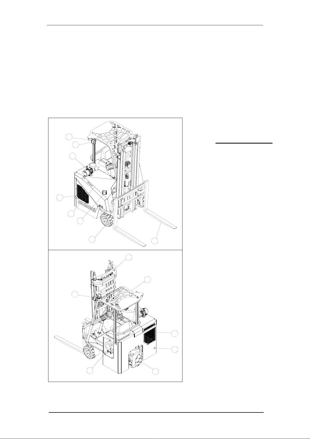
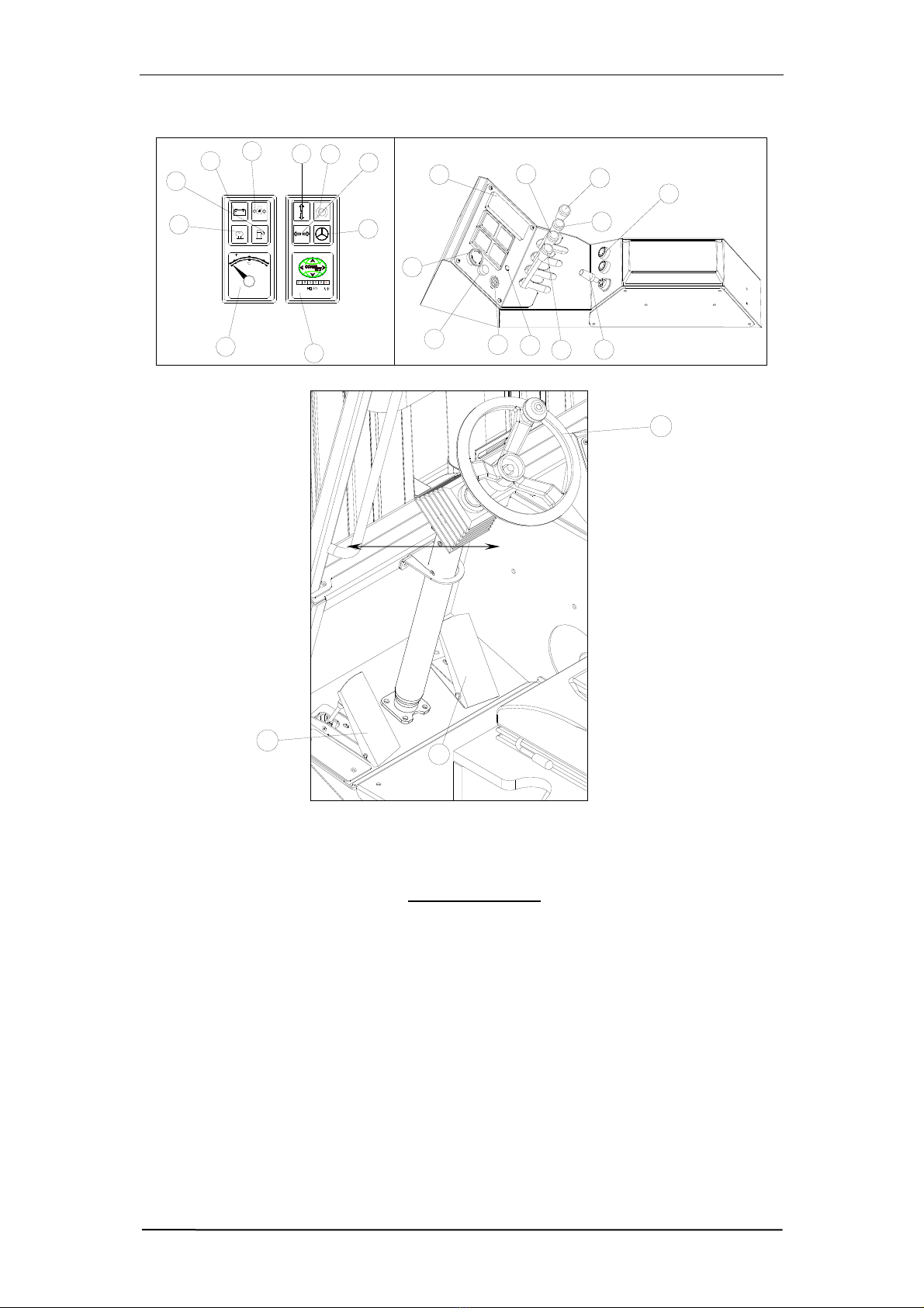
1.1:Machine Overview and Components......................................................... 1-1
Section 2:Operating instructions and Conditions .............2-1
2.1:Understand the Capacity of your Lift-Truck ............................................. 2-1
2.2:Centre of Gravity (CG).............................................................................. 2-1
2.3:Load Chart ................................................................................................. 2-2
2.4:Serial Plate................................................................................................. 2-3
2.5:Operator Qualification............................................................................... 2-3
2.6:Operator Responsibilities........................................................................... 2-3
2.7:Entering and Exiting the Operator Cabin................................................... 2-4
2.8:Starting Procedure...................................................................................... 2-4
2.9:Moving Off ................................................................................................ 2-5
2.10:Changing Direction without Changing Mode............................................ 2-5
2.11:Changing Into Sideward Mode.................................................................. 2-5
2.12:To Change Back to Forward Mode............................................................ 2-5
2.13:Stopping..................................................................................................... 2-6
2.14:Loading...................................................................................................... 2-6
2.15:When Loading in Sideward Mode............................................................. 2-6
2.16:When Loading in Forward Mode............................................................... 2-6
2.17:Placing a Load When In Sideward Mode.................................................. 2-7
2.18:Placing a Load When In Forward Mode.................................................... 2-7
2.19:Double Forking.......................................................................................... 2-7
2.20:Stacking...................................................................................................... 2-8
2.21:De-Stacking................................................................................................ 2-8
2.22:Adjusting Load Forks ................................................................................ 2-8
2.23:Operating Conditions................................................................................. 2-9
Section 3:Safe operation......................................................3-1
3.1:Safe Operation ........................................................................................... 3-1
3.2:Operating in Hazardous Areas................................................................... 3-1
3.3:Safe Driving on Gradients ......................................................................... 3-1
3.4:Driving Position......................................................................................... 3-2
3.5:Parking....................................................................................................... 3-2
3.6:Bridge Plates and Dock Boards ................................................................. 3-2
3.7:Lifting the Machine.................................................................................... 3-2

Combilift Ltd C2500-C3000CB O&S Manual
ii
C2500CB-OM-EN-11
Section 4:Maintenance & Service Information...................4-1
4.1:Maintenance Schedule............................................................................... 4-1
4.2:Operators Daily Inspection Sheet .............................................................. 4-6
4.3:Initial Service – Conducted at 100 hours of Operation.............................. 4-7
4.4:Engine Oil & Engine Oil Filter (Service Interval = 250Hours)................. 4-7
4.5:Engine Coolant (Service interval = 2000Hours)........................................ 4-9
4.6:Mast Maintenance (Service Interval = 250Hours)..................................... 4-9
4.7:Hydraulic Oil & Filters............................................................................ 4-10
4.9:Water Pump V- Belt................................................................................. 4-12
4.10:Fuel Filter – diesel engine trucks (Service interval = 500 Hours)........... 4-12
4.11:Air Filter Element (Service Interval = 500 Hours).................................. 4-12
4.12:Grease Point Chart................................................................................... 4-13
4.13:Diesel Particulate Filter (DPF)................................................................. 4-14
Section 5:Technical Information & Circuit Diagrams ........5-1
5.1Hydraulic Functions Circuit....................................................................... 5-1
5.2Hydraulic Drive Circuit ............................................................................. 5-2
5.3Towing the Combilift................................................................................. 5-3
5.4Mechanical Brake Release......................................................................... 5-4
5.5Checking the Charge Pressure................................................................... 5-5
5.6Fuse Box Layout........................................................................................ 5-6
5.7Relay Layout.............................................................................................. 5-6
5.8Standard GM LPG PLC Electric Circuit: .................................................. 5-7
5.9Standard Kubota Diesel PLC Electric Circuit: .......................................... 5-9
5.10Standard Toyota 4Y LPG PLC Electric Circuit:...................................... 5-11
5.11Tier IV GM LPG PLC Electric Circuit:................................................... 5-14
5.12Colour Codes for Electric Circuits:.......................................................... 5-16
5.13PLC Details.............................................................................................. 5-17
5.14PLC Diagnostics ...................................................................................... 5-20
Section 6:Appendices...........................................................6-1
6.1:Appendix A: Certified LPG Engine Emission Control Warranty ............. 6-1
6.2:Appendix B: General Engine Warranty..................................................... 6-2

Combilift Ltd C2500-C3000CB O&S Manual
1-1
C2500CB-OM-EN-11
Section 1: Machine layout and Operator Controls
1.1: Machine Overview and Components
It is essential before you start operating the Combilift to be familiar with the
main components and controls of the machine, their function and where they
are located. Figure 1 below and Figure 2 on the following page indicate the
major components of the machine and all of the operator controls.
Figure 1: Machine Component Layout – Front View
Component Layout
1. Forks
2. Front Swivels
3. Mast
4. Bonnet
5. Access Panels
6. Worklights
7. Strobe Beacon
8. Overhead Guard
9. Air Filter
10.LPG Tank / Diesel Tank
11.Rear Swivel
12. Exhaust
1
3
5
12
11
10
6
2
6
4
5
9
6
7
8

Combilift Ltd C2500-C3000CB O&S Manual
1-2
C2500CB-OM-EN-11
6
7
1
2
3
4810
9
5
1314151617
18
19
20
11
12
21
22
23
24
Figure 2: Machine Control Layout – Rear View
Control Layout
1. Ignition 2. Light Switch
3. Parking Brake 4. Fuse Box
5. Horn Button 6. Direction Control lever
7. Lift Control Lever 8. Tilt Control Lever
9. Sideshift Control Lever 10. Fork positioner Control Lever
11. Pre Heat indicator 12. Low Level Fuel Indicator
13. Battery Charge Indicator 14. Oil Pressure Indicator
15. Sideward Mode Indicator 16. Parking Brake Indicator
17. Normal Mode Indicator 18. Carousel Indicator
19. Hour Meter 20. Water Temperature Gauge
21. Engine Management Light 22. Steering Wheel
23. Inching Pedal 24. Accelerator Pedal

Combilift Ltd C2500-C3000CB O&S Manual
1-3
C2500CB-OM-EN-11
Ignition/Starter Switch
This is a two-position key switch that
isolates the electrical system when in the
‘OFF’ position.
Light Switch
Illuminates all work lights, dash light and cabin light.
To illuminate all lights, turn the switch clockwise.
To extinguish all lights, turn the switch anti-clockwise.
Horn Button
The horn button is located on the dash beside the
Directional control lever. Press to operate.
Direction control switch
A four-position switch which will engage any of the four
directions of travel.
To operate push lever in the desired direction of travel.
Always ensure that the Direction Control Switch to the
neutral position after bringing the truck to a halt.
Parking Brake
To APPLY brakes, PUSH button.
To RELEASE brakes, TURN BUTTON CLOCKWISE.
The machine will not drive with Parking Brake ON.
Water Temperature gauge
This gauge Monitors the temperature of the engine
cooling system
The truck must not be operated if the gauge pointer
moves to the red area as this indicates a fault in the
cooling system
Hour Meter
The hour meter records how many hours the truck has
been operating for in hours and tenths of an hour.
Use meter to determine maintenance intervals

Combilift Ltd C2500-C3000CB O&S Manual
1-4
C2500CB-OM-EN-11
Engine Management Light (Yellow Light On Dash)
If this light comes on it means the engine control unit
(ECU) has detected a problem with the engine.
If the light is on and the engine is running ok you can
drive the truck. However, it should be checked at the
earliest convenience. If the engine is running poorly
the truck should not be driven.
The ECU will store the fault information that will allow
the fault to be diagnosed when the ECU is connected to
a PC.
Oil Pressure Indicator Light
When the key switch is in the ‘ON’ position, with the
engine at rest, the oil pressure indicator is illuminated.
If the indicator is illuminated when the engine is ‘running’
then this indicates low engine oil pressure and/or
insufficient oil in the sump.
Battery Charge Indicator Light
This charging lamp indicates whether the alternator is
charging the system or not. With the key switch turned
ON and the engine not running, this red charge lamp
should illuminate.
If the charging lamp remains illuminated with the engine
running, it indicates a malfunction of the charging
system or associated components.
Pre-Heat Indicator Light – (diesel engines)
The Pre-heat indicator is a lamp connected to the glow
plugs on the diesel engine.
When operating in cold conditions, wait until the pre-
heat indicator extinguishes before attempting to start
engine
Low fuel level indicator light
The low-level indicator light illuminates whenever the
fuel level on the truck reaches a certain level.
On LPG engines a buzzer will also sound.
Whenever the light illuminates the truck should be
refuelled immediately.
Note
Do NOT run engine if oil pressure indicator is illuminated.

Combilift Ltd C2500-C3000CB O&S Manual
1-5
C2500CB-OM-EN-11
Parking Brake Indicator Light
The Parking Break indicator light indicate whether the
brake is “ON” or “OFF”
Mode Indicator Lights
The Mode indicator lights indicate which mode of travel
the machine is in.
If the machine is in normal mode, then the normal mode
indicator light will illuminate
If the machine is in sideward mode, then the sideward
mode indicator light will illuminate
Note: Modes of travel are covered in more detail in
section 3 of this manual
Carousel Indicator Light
The carousel indicator light is only used when the
machine is in sideward mode.
When the front wheels are steered in to a certain
position, the carousel indicator light will illuminate. It is at
this point that the carousel mode is activated and the
machine can turn on its own axis.
To deactivate the carousel the operator simply steers
the wheels out of the carousel position
Lift Control Lever
The lift control lever controls the lift function of the Mast.
To raise the forks, PULL the lever BACK
To lower the forks, PUSH the lever FORWARD
Tilt Control Lever
The tilt control lever controls the tilt function of the Mast.
To tilt the mast forward, PUSH the lever FORWARD
To tilt the mast backward, PULL the lever BACKWARDS
Sideshift Control Lever
The Sideshift control lever controls the sideshift
function of the forks.
To shift the forks left, PUSH the lever FORWARD.
To shift the forks, right, PULL the lever
BACKWARDS.
P
Sideward
Mode
Normal
Mode

Combilift Ltd C2500-C3000CB O&S Manual
1-6
C2500CB-OM-EN-11
Fork Positioning Control Lever
This lever controls the position of the forks on the mast
carriage. The forks can be controlled simultaneously or
individually by use of this lever.
Push lever forward to position both forks outward, pull
lever back to position forks inward.
Depress left button on top of lever to control left fork.
Push lever forward to position left fork outward. Pull
lever back to position left fork inward.
Depress right button on top of lever to control right fork.
Push lever forward to position right fork outward. Pull
lever back to position right fork inward.
IMPORTANT
A new truck capacity plate MUST be obtained from Combilift Ltd to reflect
the new maximum load capacity when ANY attachment is fitted. Only
attachments approved by Combilift Ltd personnel should be fitted.
Steering
All models have both front and rear-end steering.
When in forward mode the front wheels are fixed and the
rear wheel steers the truck.
Rear-end steering allows sharper turns in confined areas but
demands greater driver care when turning.
When in sideward mode, the rear wheel is fixed and the
front wheels steer the truck.
When driving forwards, turn steering wheel clockwise to turn
truck clockwise, turn steering wheel anticlockwise to turn
truck anti clockwise.
When driving in reverse, turn steering wheel clockwise to
turn truck anticlockwise, turn steering anti clockwise to turn
truck clockwise.
When driving sideward to the right, turn steering wheel
clockwise to turn truck clockwise, turn steering wheel
anticlockwise to turn truck anticlockwise.
When driving sideward to the left, turn steering wheel
clockwise to turn truck clockwise, turn steering wheel
anticlockwise to turn truck anticlockwise.
The steering wheel is also equipped with a spinner knob for
easier steering.

Combilift Ltd C2500-C3000CB O&S Manual
1-7
C2500CB-OM-EN-11
Brake/Inching Pedal
The combined Brake/Inching Pedal has two functions:
Stops drive to slow the machine down.
Permits slow speed, for precise manoeuvring of the
truck in confined spaces - See Section 2 for Operating
Instructions and Conditions.
Accelerator Pedal
The accelerator pedal is located on the floor on the right
hand side of the steering column.
It is used to increase the speed of the engine, therefore
increasing travel speed and / or hydraulic function
speed.
Battery Isolator Switch
This switch is used to disconnect power from the battery
in the event of an emergency.
The switch is located inside the cabin, beside the dash.
When the Combilift is not in use turn switch to ‘OFF’
by pressing switch until it clicks into the closed position.
The Combilift will not power-up unless the switch
is returned to the ‘ON’ position by pulling the switch up.
On
Off

Combilift Ltd C2500-C3000CB O&S Manual
1-8
C2500CB-OM-EN-11
Seat Adjustment
It is the responsibility of the Operator to ensure that the seat is adjusted
according to operator weight, height etc before operating the truck.
ALWAYS report any malfunctioning of the seat adjustments immediately.
ALWAYS wear the seat belt provided.
DO NOT adjust the seat when vehicle is in operation.
Keep clear of moving parts.
Authorised & competent personnel should carry out Installation &
Maintenance only.
1) The standard seat can be positioned
as the operator requires by releasing
the seat slide lever (item 1) and
moving the seat forward or back.
2) The weight adjustment is controlled
by moving the weight adjustment
lever (item 2) to increase or decrease
the firmness of the seat base
suspension. There are 5 weight
settings from 50-120 kg (110-265lbs).
3) The seat angle can be adjusted by
releasing the seat tilt lever (item 3)
and tilting the seat forward or back.
There are 2 seat tilt positions.
4) The backrest can also tilt to suit the
operator by releasing the backrest tilt
lever (item 4), and tilting the backrest
forward or back. There are three
backrest tilt settings.
1
23
4

Combilift Ltd C2500-C3000CB O&S Manual
2-1
C2500CB-OM-EN-11
Section 2: Operating instructions and Conditions
2.1: Understand the Capacity of your Lift-Truck
The basic function of a lift truck is to lift, move and place materials. It operates
on the seesaw principle - two weights on opposite sides of a fulcrum. In this
case, the load on the forks must be balanced by the weight of the Combilift.
The location of the centre of gravity of both the Combilift and the load is a
major factor.
2.2: Centre of Gravity (CG)
The centre of gravity of any object is the single
point about which the object is balanced in all
directions. Every object has a centre of gravity.
When the lift truck picks up a load, the truck and
load have a new, combined centre of gravity.
The Combilift has moving parts that change its centre of gravity. The centre of
gravity moves as the mast is tilted backwards and forwards. The centre of
gravity also moves up and down as the mast moves up and down. The centre
of gravity and therefore stability is also affected by the size, weight, shape and
position of the load; the height to which it is raised; tilt and side shift. Truck
movement such as acceleration, braking, turning and uneven surfaces will
also affect truck stability.
Combilift&Load
CombinedCentre
OfGravity
CombiliftCentre
OfGravity
LoadCentre
OfGravity

Combilift Ltd C2500-C3000CB O&S Manual
2-2
C2500CB-OM-EN-11
To keep the lift truck stable, the centre of gravity must stay within the area of
the lift truck represented by a triangle drawn between the three wheels. If the
centre of gravity moves forward of the triangle front, the lift truck will tip
forwards. If it moves outside the right or left of the triangle the truck will tip to
the side.
2.3: Load Chart
The rated capacity of the truck is illustrated
on a load chart located inside the cabin. The
load centre is determined by its centre of
gravity and is measured from the front face
of the forks to the centre of gravity of the
load. It is assumed that the centre of gravity
in the vertical direction is no greater than the
specified horizontal load centre.
It is the responsibility of the operator to determine that the weight of the load to
be handled is not greater than the capacity shown on the load chart. The
operator must not handle any load that is greater than the capacity shown.
COMPLYING WITH 89/392/EEC
MAXIMUM STACKING CAPACITY ON A FIRM LEVEL SURFACE
600 700
LIFT HEIGHT (m)
2.5
4.5
LOAD CENTRE (mm)
800 900
?Kg
5.5
1000
?Kg
?Kg
?Kg
?Kg
?Kg
?Kg
?Kg
?Kg
LoadCentre
OfGravity
CombiliftCentre
OfGravity
Combilift&Load
CombinedCentre
OfGravity

Combilift Ltd C2500-C3000CB O&S Manual
2-3
C2500CB-OM-EN-11
2.4: Serial Plate
The Serial Plate is the Metal Disc that is fixed to the Combilift in the cabin of
every machine. It is engraved with a number of details, which are required by
law. These are:
The Trucks serial Number
Its rated Capacity
It’s unladen weight
It’s date of manufacture
The manufacturers name and address.
This plate should not be removed by anyone. If lost order a replacement from
Combilift immediately.
2.5: Operator Qualification
The Combilift must NOT be operated by any other individual other than those
who have been trained to do so. Training should be carried out either by
Combilift Driver training personnel or a Combilift authorised training
organisation. Details of these organisations can be acquired from Combilift
Ltd.
2.6: Operator Responsibilities
Always ensure that the truck is in good working order before commencing
work. This is achieved by performing the Daily inspection of the Combilift. The
daily inspection is to be carried out at the beginning of the working day or at
the start of each shift.
It is the operators’ responsibility to perform the daily inspection before each
shift. The Inspection and how it should be conducted is covered later in this
publication.
Unless authorised and trained to do so, the operator must not attempt any
repairs, but report defects immediately. When authorised to perform
maintenance work and/or repairs, ALWAYS ensure that the appropriate
Health and Safety regulations are strictly adhered to.
Report any operational problems that may develop, (damaged pallets, ground
surface breaking up etc.) which could not only reduce safety but also cause
damage to the truck.
Never attempt to exceed your truck’s handling capacity and take all
precautions to ensure safety of others as well as yourself. Stop working and
switch off if for any reason, in your opinion, the truck becomes unsafe or
defective.

Combilift Ltd C2500-C3000CB O&S Manual
2-4
C2500CB-OM-EN-11
2.7: Entering and Exiting the Operator Cabin
When entering or exiting the Operator cabin of the Combilift, always use a
three point contact method to avoid slips and falls. The three point contact
method is applied by keeping 3 of the bodies 4 limbs (hands & feet) in
contact with the machine.
Always use the handles and footsteps on the machine.
NEVER use the steering wheel as a handle.
2.8: Starting Procedure
Diesel Engine
Ensure that the parking brake is applied and that the directional control
lever is in the neutral position
Insert the key into the ignition switch and turn clockwise to the preheat
position. The charge indicator lamp must light up.
Depress the accelerator.
Turn the ignition key further clockwise to the “Start” position. After the
engine starts, release the ignition key which will return automatically to
the ON position.
Check that all the indicator lamps are extinguished and that all gauges
are registering correctly.
LP Gas System
Open the valve on the LPG tank.
Ensure that the parking brake is applied and that the directional control
lever is in the neutral position
Insert the key into the ignition switch and turn clockwise to the ‘ON’
position. The charge indicator lamp must light up.
Turn the ignition key further clockwise to the ‘start’ position.
As soon as the engine starts, release the ignition key, which will
automatically return to the ‘ON’ position.
Check that all warning lamps are extinguished and that all gauges are
registering correctly
NOTE:
The truck will NOT start unless the directional control lever is in the
neutral position.
NOTE:
The starter must not be operated continuously for more than 30
Seconds. If the engine does not start, return key to the “OFF”
position and wait 10 seconds before trying again.
NOTE:
When the machine is started the wheels will remain in whatever
Position they were in when the machine was stopped until the
Operator selects a direction of travel on the direction control lever.

Combilift Ltd C2500-C3000CB O&S Manual
2-5
C2500CB-OM-EN-11
2.9: Moving Off
Ensure that the forks are as low as possible.
Select forward or reverse, or, right or left with Direction Control switch.
Look around and when all is clear release parking brake and apply light
pressure to the accelerator pedal until the truck begins to move.
Increase pressure on accelerator pedal to increase truck speed.
NOTE
The Combilift has a maximum ground speed of 10km/hr. Always adhere to all speed
limits in the area which the truck is operating
2.10:Changing Direction without Changing Mode
Remove foot from the accelerator pedal.
Gradually apply inching pedal to halt the truck.
Select change of direction and gradually increase pressure on accelerator
until truck is travelling at desired speed.
2.11:Changing Into Sideward Mode
Bring the truck slowly to a halt by depressing inching pedal fully.
Ensure that all observers stand clear of the truck.
Move the direction control switch from forward/reverse into the required
sideward direction. The wheels will automatically align themselves at right
angles to the forks.
Wait until wheels are locked and dash light is illuminated before moving
NOTE
When in sideward mode the front wheels steer the truck while the back wheel
remains fixed
2.12:To Change Back to Forward Mode
NOTE
When in sideward mode, turn the steering completely anti-clockwise at least
once. This ensures correct alignment of the front wheels in forward
mode.
Bring the truck slowly to a halt by depressing the inching pedal fully.
Ensure all observers stand clear of truck.
Move the direction control switch from left/right into the required forwards
direction.
Wheels will automatically align themselves parallel with the forks.
Wait until wheels are locked and dash light is illuminated before moving.
NOTE
When in forward mode the back wheel steers the truck, while the front wheels
remain fixed.

Combilift Ltd C2500-C3000CB O&S Manual
2-6
C2500CB-OM-EN-11
2.13:Stopping
Always brake evenly and smoothly. Violent braking may cause the load to
slip from the forks.
The forks must be lowered when the truck has stopped.
After stopping the truck, return the direction control switch to neutral.
When the operator leaves the forklift truck unattended, the parking brake
must be applied and the ignition key removed to prevent unauthorised use
NOTE
The brake/inching pedal permits slow drive speed for precise manoeuvring of
the truck in confined spaces. It operates independently of the accelerator
pedal, but if fully depressed stop drive to slow the machine down.
2.14:Loading
Do not exceed rated capacity of truck. Overloading can cause truck
instability. If in doubt, check with the load chart, located inside the cabin.
Before picking up a load adjust the forks to ensure that they are equally
spaced about the centre line of the fork carriage and as widely spaced as
possible to take the weight of the load evenly.
Check that the forks are of sufficient length. The length should be at least
two thirds of the depth (front to back) of the load.
When manoeuvring to pick up a load, avoid erratic movements that could
result in damage to the load and/or truck.
Apply parking brake when loading
2.15:When Loading in Sideward Mode
Move forward as close to the load as possible.
Manoeuvre the machine so it is at the centre of the load.
Apply parking brake.
Lower/raise the forks to the required height.
Slowly drive forks into the pallet
Lift load.
Double fork load if necessary until load is tight against face of forks. (See
section on “double forking”)
Tilt rearward to secure the load.
Lower forks until load is 150mm (6”) above the ground.
2.16:When Loading in Forward Mode
Lower/raise forks to the required height.
Manoeuvre the machine forward so it is at the centre of the load.
Apply parking brake.
Lift load.
Tilt rearward to secure load.
Double fork load if necessary until load is tight against face of forks.
Lower forks until load is 150mm (6”) above the ground.

Combilift Ltd C2500-C3000CB O&S Manual
2-7
C2500CB-OM-EN-11
2.17:Placing a Load When In Sideward Mode
Drive the machine forward as close to the placing area as possible.
Apply parking brake.
Lower/raise the forks to the required height.
Lower load.
Tilt forward.
Release parking brake.
Drive rearward until machine is clear of load
Continue to drive in the sideward direction
NOTE
When handling long length loads, drive whenever possible in the sideward
mode. Tilt elevated loads forwards, only when directly over load destination
2.18:Placing a Load When In Forward Mode
Drive machine forward as close to the placing area as possible.
Apply parking brake.
Lower/raise the forks to the required height.
Lower load.
Tilt forward.
Drive rearward until machine is clear of load
2.19:Double Forking
If it is not possible to engage forks fully when lifting a load it will be necessary
to move the load closer to the front of the machine before lifting. This can be
achieved by double forking the load.
NOTE
The lift capacity of the Combilift is reduced if the forks are not fully engaged.
To Double Fork a Load:
Raise the load slightly and drive rearward sufficiently to bring the load
closer to the machine.
Lower the load and drive forward until the load is against the fork face.
The load is now ready to be lifted.

Combilift Ltd C2500-C3000CB O&S Manual
2-8
C2500CB-OM-EN-11
2.20:Stacking
Slowly approach stack with load tilted backwards.
Stop at face of stack, select neutral and apply parking brake.
Elevate load until clear of stack top. Operate accelerator
pedal to ensure that engine speed is sufficient to prevent
stalling and to give the required lifting speed.
Move forward until load is above the stack.
Tilt mast to vertical position and lower load onto stack.
Drive rearward and lower forks to 150mm (6”) above ground
before moving off.
2.21:De-Stacking
Stop at face of stack, select neutral and apply parking brake.
Elevate forks to permit entry into pallet.
Move forward and enter the pallet with the forks.
Elevate load until clear of stack and tilt mast backwards to stabilise load.
Operate accelerator pedal to ensure that the engine speed is sufficient to
prevent stalling.
Drive rearward and lower load to 150mm (6”) above ground.
2.22:Adjusting Load Forks
Forks should be spaced as far apart as the load being moved will allow.
Both forks should always be the same distance from the centre of the fork
carriage.
To adjust, raise forks approximately 25mm (1”) off the floor.
Apply parking brake and switch off engine.
Lift up the keeper pin and slide the forks along the carriage.
When the forks are set to the desired position ensure that the keeper pin is
engaged in a slot on the top of the fork carriage bar.

Combilift Ltd C2500-C3000CB O&S Manual
2-9
C2500CB-OM-EN-11
2.23:Operating Conditions
The Combilift can operate on various surfaces but the following should be
noted
Ground Surface: Floor and road surfaces should be of adequate load
capacity, firm, smooth and level. Approaches to kerbs, railway crossings
etc. should also be firm, smooth and adequately ramped to prevent
possible displacement.
Aisle Dimensions: Aisles should be arranged to eliminate corners,
angles, inclines, steep ramps, narrow passages and low ceilings.
Headroom: Structures over aisles, which may be potential obstacles
should be defined and marked with a conspicuous colour. Low doorways
should be marked with their clearance limits.
Operating in Hazardous Areas: Standard trucks are not equipped to
operate in cold stores, flammable or explosive areas, corrosive
atmospheres or areas containing a high degree of dust contamination.
Gradients: When differences in levels exist, low gradient ramps should be
provided, having smooth, gradual level changes at top and bottom to
prevent shocks to the load or fouling of the forks. Except in emergencies,
do not turn the truck on gradients. Correct gradient procedure should be
followed at all times (see Safety Precautions) Do not park on a gradient. In
an emergency apply parking brake and chock wheels, but do not leave the
truck unattended.
This manual suits for next models
1
Table of contents
Other CombiLift Forklift manuals