manuals.online logo
Brands
  1. Home
  2. •
  3. Brands
  4. •
  5. Comelit
  6. •
  7. Keypad
  8. •
  9. Comelit UT9279M User manual

Comelit UT9279M User manual

IT
MANUALE
TECNICO
EN
TECHNICAL
MANUAL
FR
MANUEL
TECHNIQUE
RU
ТЕХНИЧЕXСКОМУ
РУКОВОДСТВУ
NL
TECHNISCHE
HANDLEIDING
TR
TEKNIK
KILAVUZU
DE
TECHNISCHES
HANDBUCH
PL
INSTRUKCJA
TECHNICZNA
ES
MANUAL
TÉCNICO
PT
MANUAL
TÉCNICO
Passion.Technology.Design.
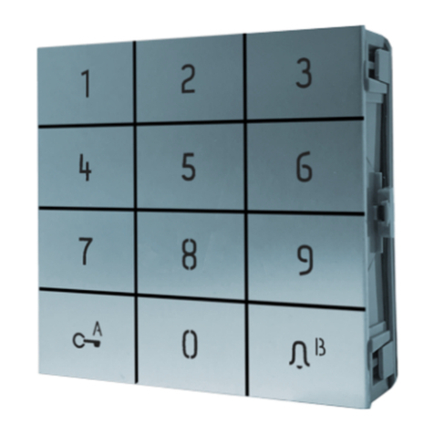
Modulo tastiera numerica
Number keypad module
Module clavier numérique
Art. UT9279M
Numeriek toetsenbordmodule
Numerisches Tastatur-Modul
Módulo teclado numérico
Модуль цифровой клавиатуры
Sayısal klavye modülü
Moduł klawiatury numerycznej
2
Avvertenze
• Questo prodotto Comelit è progettato e realizzato con lo scopo di essere
utilizzato nella realizzazione di impianti per comunicazione audio e video
in edifici residenziali, commerciali, industriali e in edifici pubblici o ad uso
pubblico.
• Tutte le attività connesse all’installazione dei prodotti Comelit devono
essere realizzate da personale tecnicamente qualificato, seguendo
attentamente le indicazioni di manuali / istruzioni dei prodotti stessi.
• Togliere l’alimentazione prima di effettuare qualsiasi operazione.
• Utilizzare conduttori con sezione adeguata in funzione delle distanze,
rispettando le indicazioni riportate nel manuale di sistema.
• Si consiglia di non posare i conduttori per l’impianto nella stessa
tubazione dove transitano i cavi di potenza (230V o superiori).
• Per l’utilizzo sicuro dei prodotti Comelit è necessario: seguire con
attenzione le indicazioni di manuali e istruzioni; curare che l’impianto
realizzato con i prodotti Comelit non sia manomesso / danneggiato.
• I prodotti Comelit non prevedono interventi di manutenzione ad
eccezione delle normali operazioni di pulizia, da effettuarsi comunque
secondo quanto indicato in manuali / istruzioni. Eventuali riparazioni
devono essere effettuate: per i prodotti, esclusivamente da Comelit
Group S.p.A., per gli impianti, da personale tecnicamente qualificato.
• Comelit Group S.p.A. non assume alcuna responsabilità per usi differenti
da quello previsto e mancato rispetto di indicazioni ed avvertenze presenti
in questo manuale / istruzioni. Comelit Group S.p.A. si riserva comunque
il diritto di modificare in qualsiasi momento e senza preavviso quanto
descritto nel presente manuale / istruzioni.
Warning
• This Comelit product was designed for use in the creation of audio and
video communication systems in residential, commercial or industrial
settings and in public buildings or buildings used by the public.
• All activities connected to the installation of Comelit products must be
carried out by qualified technical personnel, with careful observation of
the indications provided in the manuals / instruction sheets supplied with
those products.
• Cut off the power supply before carrying out any maintenance
procedures.
• Use wires with a cross-section suited to the distances involved,
observing the instructions provided in the system manual.
• We advise against running the system wires through the same duct as the
power cables (230V or higher).
• To ensure Comelit products are used safely: carefully observe the
indications provided in the manuals / instruction sheets and make sure
the system created using Comelit products has not been tampered with
/ damaged.
• Comelit products do not require maintenance aside from routine
cleaning, which should be carried out in accordance with the indications
provided in the manuals / instruction sheets. Any repair work must be
carried out: for the products themselves, exclusively by Comelit Group
S.p.A., for systems, by qualified technical personnel.
• Comelit Group S.p.A. does not assume any responsibility for: any usage
other than the intended use; non-observance of the indications and
warnings contained in this manual / instruction sheet. Comelit Group
S.p.A. nonetheless reserves the right to change the information provided
in this manual / instruction sheet at any time and without prior notice.
Avertissements
• Ce produit Comelit a été conçu et réalisé pour être utilisé dans la
réalisation d'installations de communication audio et vidéo dans des
bâtiments résidentiels, commerciaux, industriels et publics ou à usage
public.
• Toutes les opérations liées à l'installation des produits Comelit sont
réservées à des techniciens qualifiés qui devront suivre attentivement les
consignes des Manuels / Instructions desdits produits.
• Couper l'alimentation avant d'effectuer toute opération.
• Utiliser des conducteurs d'une section adéquate en fonction des
distances et en respectant les explications contenues dans le manuel
du système.
• Il est conseillé de ne pas poser les conducteurs destinés à l’installation
dans la canalisation destinée aux câbles de puissance (230 V ou plus).
• Pour utiliser les produits Comelit en toute sécurité : suivre attentivement
les consignes contenues dans les Manuels / Instructions; s'assurer
que l’installation réalisée avec les produits Comelit n'est pas sabotée
/ endommagée.
• Les produits Comelit sont sans maintenance, exception faite pour les
opérations de nettoyage qui devront être effectuées selon les consignes
contenues dans les Manuels / Instructions. Les réparations concernant :
les produits, sont réservées exclusivement à Comelit Group S.p.A., les
installations, sont réservées à des techniciens qualifiés.
• Comelit Group S.p.A. ne sera pas tenue pour responsable en cas
d'utilisation contraire aux indications, de non-respect des indications et
des recommandations présentes dans ce Manuel / Instructions. Comelit
Group S.p.A. se réserve le droit de modifier à tout moment et sans
préavis le contenu de ce Manuel / Instructions.
Waarschuwingen
• Dit product van Comelit is ontworpen en ontwikkeld om te worden
gebruikt bij de realisatie van audio- en videocommunicatiesystemen In
woningen, winkels, bedrijven en openbare gebouwen of in openbare
ruimtes.
• Alle functies die zijn aangesloten op de installatie van de Comelit-
producten moeten zijn uitgevoerd door gekwalificeerd technisch
personeel, volgens de aanwijzingen in de handleiding/instructies van de
betreffende producten.
• Sluit de voeding af voordat u onderhoudswerkzaamheden uitvoert.
• Gebruik geleiders met een geschikte doorsnede, afhankelijk van de
afstanden, volgens de aanwijzingen in de handleiding van de installatie.
• Het is raadzaam om de kabels voor de installatie niet in dezelfde leiding
te plaatsen als die waar de vermogenskabels (230v of hoger) doorheen
lopen.
• Voor een veilig gebruik van de producten Comelit is het volgende
noodzakelijk: het zorgvuldig opvolgen van de aanwijzingen in de
handleiding/instructies, ervoor zorgen dat de installatie die met de
Comelit-producten is uitgevoerd niet wordt gesaboteerd / beschadigd
raakt.
• De producten van Comelit hebben geen onderhoud nodig, behalve de
normale reiniging, welke moet worden uitgevoerd zoals is aangegeven
in de handleiding/instructies. Eventuele reparaties moeten worden
uitgevoerd voor de producten, uitsluitend door Comelit Group S.p.A.,
voor de installatie, door gekwalificeerd technisch personeel.
• Comelit Group S.p.A. is niet verantwoordelijkheid voor andere
toepassingen dan het beoogde gebruik, het niet in acht nemen van
de aanwijzingen en waarschuwingen in deze handleiding/instructies.
Comelit Group S.p.A. behoudt zich het recht voor om op elk moment,
zonder waarschuwing vooraf, wijzigingen aan te brengen in deze
handleiding/instructies.
Hinweise
• Dieses Comelit-Produkt ist für den Einsatz in Anlagen für Audio-
und Video-Kommunikation in Wohngebäuden, Gewerbe- und
Industrieanlagen, in öffentlichen Gebäuden und für den öffentlichen
Gebrauch konzipiert.
• Die Installation der Comelit-Produkte darf nur durch Fachkräfte unter
genauer Befolgung der Anweisungen in den technischen Handbüchern /
den Bedienungsanleitungen erfolgen.
• Vor Eingriffen an der Anlage immer die Spannungsversorgung
unterbrechen.
• Leiter mit einem für die Entfernung bemessenen Querschnitt verwenden
und die im Handbuch der Anlage aufgeführten Anweisungen einhalten.
• Es wird empfohlen, die Leiter der Anlage nicht in den Rohren der
Leistungskabel (230 V oder höher) zu verlegen.
• Sicherer Umgang mit Comelit-Produkten: Halten Sie sich strikt an die
Angaben in den technischen Handbüchern / den Bedienungsanleitungen.
Nehmen Sie keine Änderungen an der Anlage mit Comelit-Produkten vor
und vermeiden Sie Beschädigungen.
• Die Comelit-Produkte erfordern keine Wartungsarbeiten, abgesehen
von der normalen Reinigung, die entsprechend den Anweisungen in den
technischen Handbüchern / den Bedienungsanleitungen auszuführen
ist. Eventuelle Reparaturen dürfen für die Produkte nur durch die Firma
Comelit Group S.p.A., an der Anlage nur durch Fachkräfte ausgeführt
werden.
• Comelit Group S.p.A. lehnt jede Haftung ab bei Schäden durch
bestimmungsfremden Gebrauch, Missachtung der Anweisungen
und Hinweise in dem vorliegenden technischen Handbuch / den
Bedienungsanleitungen. Comelit Group S.p.A. behält sich vor, jeder
Zeit und ohne Vorankündigung Änderungen an dem vorliegenden
technischen Handbuch / den Bedienungsanleitungen vorzunehmen.
Advertencias
• Este producto Comelit ha sido diseñado y realizado para usarse
en instalaciones de comunicación audio y vídeo tanto en edificios
residenciales, comerciales e industriales como en edificios públicos o
de uso público.
• Todos los productos Comelit deben ser instalados por personal
técnicamente cualificado, siguiendo con atención las indicaciones de los
manuales / las instrucciones proporcionados con cada producto.
3
• Antes de efectuar cualquier operación hay que cortar la alimentación.
• Utilizar conductores de sección adecuada teniendo en cuenta las
distancias y respetando las instrucciones del manual de sistema.
• Se aconseja no colocar los conductores de la instalación en el mismo
conducto eléctrico por donde pasan los cables de potencia (230 V o
superiores).
• Para el uso seguro de los productos Comelit, es necesario seguir con
atención las indicaciones de los manuales / las instrucciones e garantizar
que la instalación realizada con los productos Comelit no pueda ser
manipulada ni dañada.
• Los productos Comelit no prevén intervenciones de mantenimiento, salvo
las normales operaciones de limpieza, que se deben efectuar siempre
según lo indicado en los manuales / las instrucciones. Las reparaciones
deben ser efectuadas: exclusivamente por Comelit Group S.p.A. cuando
afecten a productos, por personal técnicamente cualificado cuando
afecten a instalaciones.
• Comelit Group S.p.A. quedará libre de cualquier responsabilidad en caso
de usos diferentes a los previstos e incumplimiento de las indicaciones y
advertencias proporcionadas en el manual / las instrucciones. Comelit
Group S.p.A. se reserva siempre el derecho de modificar en cualquier
momento y sin preaviso el manual / las instrucciones.
Avisos
• Este produto Comelit foi concebido e realizado com o intuito de ser
utilizado na realização de instalações para comunicação áudio e
vídeo em edifícios residenciais, comerciais, industriais, públicos ou de
utilização pública.
• Todas as actividades relacionadas com a instalação de produtos Comelit
devem ser realizadas por pessoal tecnicamente qualificado, seguindo
atentamente as indicações dos manuais/instruções dos respectivos
produtos.
• Cortar a alimentação eléctrica antes de realizar qualquer tipo de
operação.
• Utilizar condutores de secção adequada em função das distâncias e
respeitando as indicações no manual do sistema.
• Recomenda-se não colocar condutores para a instalação nas mesmas
condutas onde se encontram os cabos de energia (230 V ou superior).
• Para a utilização segura dos produtos Comelit é necessário: Seguir com
atenção as indicações dos manuais/instruções, Certificar-se de que a
instalação realizada com produtos Comelit não é adulterada/danificada.
• Os produtos Comelit não requerem intervenções de manutenção além
das normais operações de limpeza, que devem ser realizadas segundo
as indicações nos manuais/instruções. Eventuais reparações devem ser
realizadas: no caso de produtos, exclusivamente pela Comelit Group
S.p.A., no caso de instalações, por pessoal tecnicamente qualificado.
• Comelit Group S.p.A. não assume qualquer responsabilidade por
utilizações diferentes das previstas e desrespeito pelas indicações e avisos
presentes neste manual/instruções. Comelit Group S.p.A. reserva-se o
direito de modificar a qualquer momento e sem aviso prévio o descrito no
presente manual/instruções.
Предупреждения
• Данное изделие Comelit было разработано и изготовлено с целью
его дальнейшего использования при реализации систем аудио- и
видеосвязи в жилых, коммерческих, промышленных и общественных
зданиях или помещениях для общественного пользования.
• Все работы, связанные с установкой продукции Comelit, должны
выполняться квалифицированным техническим персоналом в
тщательном соблюдении инструкций/ руководств на саму продукцию.
• Отключайте электропитание перед выполнением любых работ.
• Используйте кабели соответствующего сечения в зависимости от
расстояний, соблюдая указания, приведенные в руководстве по
эксплуатации системы.
• Рекомендуется не располагать кабели для системы в той же трубе, где
проходят силовые кабели (230 В или выше).
• Для безопасного использования продукции Comelit необходимо:
внимательно следовать указаниям руководств/инструкций;
заботиться о предупреждении несанкционированного вмешательства/
повреждения оборудования, реализованного с использованием
продукции Comelit.
• Продукция Comelit не предусматривает технического обслуживания,
за исключением обычных операций по очистке, которые, в любом
случае, должны проводиться согласно указаниям руководств/
инструкций. Ремонтные работы должны выполняться: на продукции
- исключительно компанией Comelit Group S.p.A., на системах -
квалифицированным техническим персоналом.
• Comelit Group S.p.A. не несет никакой ответственности в случае
использования, отличающегося от предусмотренного; несоблюдения
инструкций и предупреждений, приведенных в данном руководстве/
инструкциях. Comelit Group S.p.A., тем не менее, оставляет за собой
право в любой момент вносить изменения в содержание данного
руководства/инструкций без предварительного уведомления.
Uyarılar
• Bu Comelit ürünü, konutlar, ticari, endüstriyel binalarda ve kamu binaları
veya kamusal kullanıma açık binalarda işitsel ve görsel iletişim sistemlerinin
gerçekleştirilmesi amacıyla tasarlanmış ve gerçekleştirilmiştir.
• Comelit ürünlerinin kurulumu ile ilgili tüm faaliyetler, teknik açıdan kalifiye
personel tarafından, bu ürünler için düzenlenmiş Kullanım/Talimat
Kılavuzlarında yer alan hususlar dikkatle izlenerek yürütülmelidir.
• Herhangi bir işlem yapmadan önce beslemeyi kesiniz.
• Sistem kullanım kılavuzunda yer alan talimatlara uyarak, mesafeye göre
uygun kesitli kablolar kullanınız.
• Tesis kablolarını güç kablolarının (230V veya daha yüksek) geçtiği borularla
aynı boruların içine döşememeniz önerilir.
• Comelit ürünlerinin güvenli kullanımı için aşağıdaki hususlara uyulmalıdır:
kılavuzları/talimatları dikkatle takip etmek, Comelit ürünleri ile gerçekleştirilen
sistemin kurcalanmamış/hasar görmemiş olmasına dikkat etmek.
• Comelit ürünleri, Kılavuzlarda/Talimatlarda verilen bilgilere göre
gerçekleştirilmesi gereken normal temizlik işlemleri haricinde bakım
müdahaleleri gerektirmemektedir. Olası tamiratlar aşağıdaki yetkililerce
yapılmalıdır: ürünler için sadece Comelit Group S.p.A. tarafından, sistemler
için, teknik açıdan kalifiye personel tarafından.
• Comelit Group S.p.A., aşağıdaki durumlarda herhangi bir sorumluluk kabul
etmemektedir öngörülenlerden farklı kullanımlarda, bu Kılavuz/Talimat
kitapçığında yer alan talimatlara ve uyarılara uyulmaması durumunda.
Comelit Group S.p.A. istediği zaman ve önceden herhangi bir uyarıda
bulunmaksızın bu Kılavuz/Talimat Kitapçığındaki bilgilerde değişiklikler
yapabilir.
Ostrzeżenia
• Ten produkt Comelit został zaprojektowany i wykonany w celu
wykorzystania go do instalacji komunikacji audio i video w budynkach
mieszkalnych, handlowych, przemysłowych oraz w budynkach publicznych
lub użyteczności publicznej.
• Wszelkie czynności dotyczące instalacji produktów Comelit muszą
być wykonane przez personel technicznie wykształcony, stosując się
skrupulatnie do zaleceń zawartych w Podręcznikach / Instrukcjach obsługi
produktów.
• Przed wykonaniem jakiejkolwiek czynności odłączyć zasilanie.
• Stosować przewody o przekroju odpowiednim do odległości, przestrzegając
zaleceń zawartych w instrukcji systemu.
• Zaleca się, aby nie kłaść przewodów dla instalacji w tym samym przewodzie
rurowym, w którym przebiegają kable elektryczne (230V lub większej mocy).
• Aby bezpiecznie użytkować produkty, należy: uważnie przestrzegać
zaleceń podanych w Podręcznikach / Instrukcjach obsługi, pilnować, aby
instalacja, w której stosowane są produkty Comelit, nie została naruszona
/ uszkodzona.
• Produkty Comelit nie wymagają czynności konserwacyjnych, za wyjątkiem
zwykłego czyszczenia, które należy wykonać zgodnie z wytycznymi
podanymi w Podręcznikach / Instrukcjach obsługi. Ewentualne naprawy
muszą być wykonane: dla produktów, wyłącznie przez Comelit Group
S.p.A., dla instalacji, przez personal technicznie wykształcony.
• Comelit Group S.p.A. nie ponosi żadnej odpowiedzialności w przypadku
użytkowania różnego od dozwolonego, nieprzestrzegania zaleceń oraz
ostrzeżeń zawartych w niniejszym Podręczniku / Instrukcji obsługi.
Jednakże spółka Comelit Group S.p.A. zastrzega sobie prawo do zmiany w
jakimkolwiek momencie i bez uprzedzenia treści w niniejszym Podręczniku
/ Instrukcji obsługi
4
Modulo con tastiera numerica per pulsantiera Ultra,
compatibile con tutti i sistemi. Utilizzabile come modulo
per chiamare direttamente l'utente conoscendone
il codice e per la funzione di controllo accessi con
attivazione dei relè a bordo e delle uscite dei moduli
audio o audio/video e degli attuatori dell'impianto. I
codici di accesso possono essere permanenti (sempre
validi), a consumo (validi per un certo numero di utilizzi)
o associati ad una data di validità. In quest’ultimo
caso ad ogni codice è possibile assegnare data inizio/
fine validità, doppia fascia oraria giornaliera, giorni di
validità. Ad ogni codice di accesso possono essere
assegnate fino a 4 diverse azioni. È possibile attivare
la funzione di riproduzione del relativo messaggio
audio alla pressione di ogni tasto. È presente altresì un
registro eventi completo di tutte le informazioni (codici
attivati, utente che li ha utilizzati, utenti chiamati,
ecc.) in cui sono memorizzabili fino a 1275 eventi.
Dispone di uscita Wiegand per l'interfacciamento con
sistemi di controllo accessi. Spegnimento automatico
della retroilluminazione dei pulsanti durante le ore
diurne attraverso il sensore crepuscolare del modulo
audio o audio/video abbinato. Rivestimento in lega
di alluminio anodizzato. Dimensioni: 100x90x35mm
(1 modulo Ultra).
1. Tasto chiave
2. Tastiera numerica
3. Tasto Campana / LED di stato
4. Micro USB per collegamento al computer
5. JP1 jumper per accedere alla programmazione
JP1
funzionamento
normale
JP1
modalità
programmazione
attiva
6. Morsettiera di connessione:
RK ingresso apriporta locale
CK ingresso funzione orologio per
abilitazione tasto chiave
GND negativo per CK e RK
NO1 NC1 COM1 contatti relè 1
NO2 COM2 contatti relè 2
V- V+ ingresso alimentazione
12-33VDC o 12-24VAC, per
utilizzo in modalità stand-alone
(senza modulo audio o audio/
video Ultra)
D1 D0 GND collegamento uscita Wiegand
IN feedback di avvenuto
comando sull'uscita Wiegand
7. Connettore per collegamento moduli
precedenti/successivi
Descrizione
Description
Description
Beschrijving
Beschreibung
1. 2. 3. 6.5.
4.
7.
Descripción
Descrição
Описание
Açıklama
Opis
5
Module with number keypad for Ultra entrance
panel, compatible with all systems. Can be used
as a module for calling the user directly when
the code is known and for access control with the
activation of built-in relays and audio or audio/video
module outputs, and system actuators. The access
codes may be permanent (always valid), metered
(valid for a certain number of uses) or associated
with a validity date. In the latter case, each code
can be assigned a validity start/end date, dual daily
time band and validity days. Each access code can
be assigned up to 4 different actions. The playback
function for playing the relevant audio message
when each button is pressed can be enabled. There
is also an event log, complete with all information
(activated codes, user that used them, users called,
etc.), which can store up to 1275 events. It has a
Wiegand output for interfacing with access control
systems. Automatic button backlight deactivation
during daylight hours using the twilight sensor for
the paired audio or audio/video module. Anodised
aluminium alloy coating. Dimensions: 100x90x35 mm
(1 Ultra module).
1. Key button
2. Number keypad
3. Bell key / status LED
4. Micro USB for connection to the computer
5. JP1 jumper for programming access
JP1
normal operation
JP1
programming
mode active
6. Terminal block for connection:
RK local lock-release input
CK trade function input for key
button enabling
GND negative for CK and RK
NO1 NC1 COM1 relay 1 contacts
NO2 COM2 relay 2 contacts
V- V+ 12-33 VDC or 12-24 VAC
power supply input, for use
in stand-alone mode (without
Ultra audio or audio/video
module)
D1 D0 GND Wiegand output connection
IN Wiegand output command
successful feedback
7. Connector for connecting previous/next
modules
Module avec clavier numérique pour platine Ultra,
compatible avec tous les systèmes. Utilisable comme
module pour appeler directement l'usager dont
l’on connaît le code et pour la fonction de contrôle
d’accès avec activation des relais embarqués et
des sorties des modules audio ou audio/vidéo et
des actionneurs de l'installation. Les codes d’accès
peuvent être permanents (toujours valides), à
consommation (valides un certain nombre de fois) ou
associés à une date de validité. Dans ce dernier cas,
chaque code pourra être attribué à une date de début/
fin de validité à chaque code, à une double tranche
horaire quotidienne ou à des jours de validité. Chaque
code d’accès peut être attribué à 4 actions maximum.
Il est possible de valider la fonction de reproduction du
message audio correspondant en appuyant sur chaque
touche. Le module dispose également d’un registre
évènements contenant toutes les informations (codes
activés, usager qui les a utilisés, usagers appelés,
etc.) et pouvant enregistrer jusqu’à 1275 évènements.
Dispose d'une sortie Wiegand pour l'interface avec les
systèmes de contrôle d’accès. Extinction automatique
du rétroéclairage des boutons pendant la journée à
travers le détecteur crépusculaire du module audio
ou audio/vidéo associé. Revêtement en alliage
d'aluminium anodisé. Dimensions : 100 x 90 x 35 mm
(1 module Ultra).
1. Touche clé
2. Clavier numérique
3. Touche sirène / led d’état
4. Micro USB pour connexion à l’ordinateur
5. JP1 cavalier pour accéder à la programmation
JP1
fonctionnement
normal
JP1
modalité de
programmation
activée
6. Bornier de connexion :
RK entrée ouvre-porte local
CK entrée fonction horloge pour
validation touche clé
GND négatif pour CK et RK
NO1 NF1 COM1 contacts relais 1
NO2 COM2 contacts relais 2
V- V+ entrée alimentation 12-33 Vcc
ou 12-24 Vca, pour utilisation
en modalité stand-alone (sans
module audio ou audio/vidéo
Ultra)
D1 D0 GND connexion sortie Wiegand
IN Suivi de la commande exécutée
sur la sortie Wiegand
7. Connecteur des modules précédents/suivants
6
Module met numeriek toetsenbord voor deurstation
Ultra, compatibel met alle systemen. Te gebruiken als
module om een directe oproep naar een gebruiker
te versturen indien de code bekend is en voor de
functie toegangscontrole met activering van de
ingebouwde relais en van de uitgangen van de audio-
of audio/videomodules en van de systeemrelais. De
toegangscodes kunnen permanent zijn (altijd geldig),
beperkt geldig (geldig voor een bepaald aantal
keren gebruik) of kunnen gekoppeld zijn aan een
geldigheidsdatum. In het laatste geval kan er aan elke
code een start/einddatum van de geldigheid worden
toegekend, een dubbel dagelijks tijdslot of bepaalde
geldigheidsdagen. Aan elke toegangscode kunnen
maximaal 4 verschillende acties worden gekoppeld.
Het is mogelijk om de afspeelfunctie van het
betreffende audiobericht te activeren bij het indrukken
van een toets. Er is ook een gebeurtenissenlogboek
aanwezig met alle bijbehorende informatie
(geactiveerde codes, gebruikers die ze hebben
gebruikt, opgeroepen gebruikers, enz.) waarin
maximaal 1275 gebeurtenissen kunnen worden
opgeslagen. Uitgerust met Wiegand uitgang voor de
communicatie met de toegangscontrolesystemen.
Automatische uitschakeling van de verlichting van
de drukknoppen overdag via de schemersensor
van de audiomodule of gecombineerde audio/
videomodule. Coating van geanodiseerde
aluminiumlegering. Afmetingen: 100x90x35mm
(1 module Ultra).
1. Sleuteltoets
2. Numeriek toetsenbord
3. Beltoets / statusled
4. Micro USB voor aansluiting op de computer
5. JP1 jumper om naar de programmering te
gaan
JP1
normale werking
JP1
modus
programmering
actief
6. Klemmenblok:
RK ingang lokale
deurslotbediening
CK ingang klokfunctie voor
inschakeling sleuteltoets
GND min voor CK en RK
NO1 NC1 COM1 relaiscontacten 1
NO2 COM2 relaiscontacten 2
V- V+ voedingsingang 12-33 Vdc
of 12-24 Vac, voor gebruik
in stand-alone (zonder Ultra
audio- of audio/videomodule)
D1 D0 GND aansluiting Wiegand uitgang
IN feedback opdracht uitgevoerd
via Wiegand-uitgang
7. Connector voor aansluiting van eerdere/
volgende modules
Numerisches Tastatur-Modul für Ultra Türstation, mit
allen Systemen kompatibel. Verwendbar als Modul
zum Direktruf des Teilnehmers, wenn dessen Code
bekannt ist und zur Zutrittskontrolle mit Aktivierung
der eingebauten Relais und der Ausgänge der Audio-
und Audio/Video-Module und der Relais der Anlage.
Die Zugangscodes können permanent (immer gültig),
nach Verbrauch (gültig für eine bestimmte Anzahl
an Verwendungen) oder mit einem Gültigkeitsdatum
verknüpft sein. Im letzten Fall besteht die Möglichkeit,
jedem Code ein Anfangs- und Enddatum der Gültigkeit,
zwei Tageszeitzonen oder Gültigkeitstage zuzuweisen.
Jedem Zugangscode können bis zu 4 unterschiedliche
Aktionen zugewiesen werden. Es ist möglich, bei
jedem Tastendruck die Wiedergabefunktion der
entsprechenden Audio-Nachricht zu aktivieren.
Es ist auch ein Ereignisprotokoll mit sämtlichen
Informationen (aktivierte Codes, Teilnehmer, der sie
benutzt hat, angerufene Teilnehmer etc.) vorhanden,
in dem bis zu 1275 Ereignisse speicherbar sind. Es
verfügt über einen Wiegand-Ausgang zur Verbindung
mit Zutrittskontrollsystemen. Automatische
Abschaltung der Tastenbeleuchtung tagsüber durch
den kombinierten Dämmerungssensor des Audio-
oder Audio/Video-Moduls. Beschichtung mit eloxierter
Aluminiumlegierung. Abmessungen: 100x90x35mm
(1 Ultra-Modul).
1. Schlüsseltaste
2. Numerische Tastatur
3. Klingeltaste / Status-LED
4. Micro-USB für Anschluss an Computer
5. JP1 Jumper für Zugri auf Programmierung
JP1
Normalbetrieb
JP1
Aktiver
Programmiermodus
6. Anschlussklemmleiste:
RK
Eingang lokaler Türöner
CK Eingang Uhr-Funktion zur
Aktivierung der Schlüsseltaste
GND Minus für CK und RK
NO1 NC1 COM1 Kontakte Relais 1
NO2 COM2 Kontakte Relais 2
V- V+ Versorgungseingang 12-
33VDC oder 12-24VAC, zur
Verwendung im Stand-alone-
Betrieb (ohne Audio- oder
Audio/Video-Modul Ultra)
D1 D0 GND Anschluss Wiegand-Ausgang
IN Feedback über erfolgten Befehl
an Wiegand-Ausgang
7. Steckverbinder zum Anschluss der vorherigen/
folgenden Module
7
Módulo con teclado numérico para placa de calle
Ultra, compatible con todos los sistemas. Se puede
utilizar como módulo para llamar directamente al
usuario, si se conoce su código, o para la función
de control de accesos, con activación de los relés
a bordo o de las salidas de los módulos audio o
audio/vídeo y de los actuadores de la instalación. Los
códigos de acceso pueden ser permanentes (siempre
válidos), de consumo (válidos para un cierto número
de usos) o asociados a una fecha de validez. En este
último caso, a cada código se le puede asignar una
fecha de inicio/fin de la validez, doble franja horaria
diaria y días de validez. A cada código de acceso
se le pueden asignar hasta 4 acciones diferentes.
Es posible activar la función de reproducción del
correspondiente mensaje de audio pulsando cada una
de las teclas. También hay un registro de eventos con
toda la información (códigos activados, usuario que
los ha utilizado, usuarios llamados, etc.) en el que se
pueden memorizar hasta 1275 eventos. Dispone de
una salida Wiegand para la conexión con los sistemas
de control de accesos. Apagado automático de la
retroiluminación de los pulsadores durante el día
mediante el sensor crepuscular del módulo audio o
audio/vídeo asociado. Revestimiento de aleación de
aluminio anodizado. Dimensiones: 100x90x35 mm
(1 módulo Ultra).
1. Tecla llave
2. Teclado numérico
3. Tecla Campana/Led de estado
4. Micro USB para la conexión al ordenador
5. JP1 puente para acceder a la programación
JP1
funcionamiento
normal
JP1
modo
programación
activo
6. Regleta de conexiones:
RK
entrada para abrepuertas local
CK entrada para la función reloj
para habilitar la tecla llave
GND negativo para CK y RK
NO1 NC1 COM1 contactos de relé 1
NO2 COM2 contactos de relé 2
V- V+ entrada para alimentación de
12-33 Vcc o 12-24 Vca, para
uso en modo stand-alone (sin
módulo audio o audio/vídeo
Ultra)
D1 D0 GND conexión de la salida Wiegand
IN feedback de mando ejecutado
en la salida Wiegand
7. Conector para la conexión de los módulo
anteriores/posteriores
Módulo com teclado numérico para botoneira Ultra,
compatível com todos os sistemas. Utilizado como
módulo para chamar directamente o utilizador
através do código, se conhecido, e para a função
de controlo de acessos com activação dos relés
a bordo e das saídas dos módulos áudio ou áudio/
vídeo e dos actuadores da instalação. Os códigos de
acesso podem ser permanentes (sempre válidos), por
utilização (válidos por um determinado número de
utilizações) ou associados a uma data de validade.
Neste último caso, a cada código pode ser atribuída
uma data de início/fim de validade, o dobro da faixa
horária diária e dias de validade. Cada código de
acesso pode ter até 4 acções diferentes. É possível
activar a função de reprodução da mensagem de
áudio relevante ao premir cada tecla. Além disso,
também existe um registo de eventos com todas
as informações (códigos activados, utilizadores
que os utilizaram, utilizadores chamados, etc.), no
qual podem ser armazenados até 1275 eventos.
Possui saída Wiegand para interface com sistemas
de controlo de acessos. Desactivação automática
da retroiluminação dos botões durante o dia
através do sensor crepuscular do módulo áudio ou
áudio/vídeo associado. Revestimento em liga de
alumínio anodizado. Dimensões: 100x90x35 mm
(1 módulo Ultra).
1. Tecla chave
2. Teclado numérico
3. Tecla campainha/LED de estado
4. Micro USB para ligação ao computador
5. JP1 comutador de derivação para aceder à
programação
JP1
funcionamento
normal
JP1
modo
programação
activa
6. Bateria de bornes de ligação:
RK
entrada abertura da porta local
CK entrada função relógio para
activar a tecla chave
GND negativo para CK e RK
NO1 NC1 COM1 contactos relé 1
NO2 COM2 contactos relé 2
V- V+ entrada de alimentação 12–33
V CC ou 12–24 V CA, para
utilização em modo stand-
alone (sem módulo áudio ou
áudio/vídeo Ultra)
D1 D0 GND ligação da saída Wiegand
IN feedback de comando
realizado na saída Wiegand
7. Conector para a ligação dos módulos
anteriores/seguintes.
8
Модуль с цифровой клавиатурой для пульта Ultra,
совместимый со всеми системами. При знании кода
его можно использовать в качестве модуля для
прямого вызова абонента, а также для контроля
доступа с активацией встроенных реле и выходов
аудио- или аудио/видеомодулей и исполнительных
механизмов системы. Коды доступа могут быть
постоянными (всегда действительными), с
лимитным использованием (действительными для
определенного количества использований) или
связанными с датой действия. В последнем случае
каждому коду можно присвоить дату начала/
окончания действия, двойной временной суточный
интервал, дни действия. Каждому коду доступа
можно присвоить до 4 различных действий.
Можно активировать функцию воспроизведения
соответствующего аудиосообщения при нажатии
каждой клавиши. Также, имеется журнал событий
со всей информацией (активированные коды,
использовавшие их пользователи, вызываемые
абоненты и т. д.), в котором может храниться
до 1275 событий. Имеет выход Wiegand для
взаимодействия с системами контроля доступа.
Автоматическое отключение подсветки кнопок
в дневное время с помощью сумеречного
датчика сопряженного аудио- или аудио/
видеомодуля. Покрытие из анодированного
алюминиевого сплава. Размеры: 100x90x35 мм
(1 модуль Ultra).
1. Кнопка "Ключ"
2. Цифровая клавиатура
3. Кнопка "Колокольчик"/СИД состояния
4. Micro-USB для подключения к компьютеру
5. JP1 перемычка для переключения в режим
программирования
JP1
нормальная
работа
JP1
активный режим
программирования
6. Соединительная клеммная колодка:
RK
вход локального открытия двери
CK вход функции часов для
подключения кнопки "Ключ"
GND отрицательный для CK и RK
NO1 NC1 COM1 контакты реле 1
NO2 COM2 контакты реле 2
V- V+ Вход питания 12-33 В пост.
тока или 12-24 В пер. тока для
использования в автономном
режиме (без аудио- или аудио/
видеомодуля Ultra)
D1 D0 GND выходное соединение Wiegand
IN обратная связь о команде на
выходе Wiegand
7. Разъем для подключения предыдущих/
последующих модулей
Tüm sistemlerle uyumlu, Ultra tuş paneli için sayısal
klavye ile donatılmış modül. Kodu kullanarak kullanıcıyı
doğrudan aramak için ve makine üzerindeki
rölelerin ve ses veya ses/video modüllerinin ve
sistem aktüatörlerinin çıkışlarının etkinleştirilmesi
ile erişim kontrol işlevi için kullanılabilen bir modül.
Erişim kodları kalıcı olabilir (her zaman geçerli),
kullandıkça öde (belirli sayıda kullanım için geçerli)
veya bir geçerlilik tarihiyle ilişkilendirilebilir. İkinci
durumda, her koda bir başlangıç/bitiş geçerlilik
tarihi, çift günlük zaman aralığı, geçerlilik günleri
atanabilir. Her erişim koduna 4 adede kadar farklı
eylem atanabilir. Herhangi bir tuşa basarak ilgili sesli
mesajı yeniden oynatma işlevini etkinleştirebilirsiniz.
Ayrıca olayların 1275 adede kadar saklanabileceği tüm
bilgileri (etkinleştirilen kodlar, bunları kullanan kullanıcı,
aranan kullanıcılar vb.) içeren eksiksiz bir olay günlüğü
vardır. Erişim kontrol sistemleri ile arayüz oluşturmak
için bir Wiegand çıkışına sahiptir. Eşleştirilmiş ses
veya ses/video modülünün alacakaranlık sensörü
aracılığıyla gün boyunca tuşların arka aydınlatmasının
otomatik olarak kapatılması. Eloksallı alüminyum
alaşımlı kaplama. Boyutlar: 100x90x35mm
(1 Ultra modülü).
1. Anahtar tuşu
2. Sayısal klavye
3. Zil Tuşu / Durum Led’i
4. Bilgisayara bağlantı için Mikro USB
5. Programlama erişimi için JP1 jumper
JP1
normal çalışma
JP1
programlama
modu etkin
6. Bağlantı klemens kutusu:
RK
yerel kapı açma girişi
CK anahtar tuşu etkinleştirmek için
saat fonksiyonu girişi
GND CK ve RK için negatif
NO1 NC1 COM1 röle 1 kontakları
NO2 COM2 röle 2 kontakları
V- V+ bağımsız modda kullanım için
12-33VDC veya 12-24VAC güç
girişi (ses veya ses/video Ultra
modülü olmadan)
D1 D0 GND Wiegand çıkış bağlantısı
IN Wiegand çıkışında başarılı
komut geri bildirimi
7. Önceki/sonraki modülleri bağlamak için
konnektör
9
Materiale Policarbonato, Alluminio
anodizzato
Sistemi compatibili Tutti i sistemi
N° utenti/codici apriporta
memorizzabili 4000
Numero log memorizzabili 1275
Colore della
retroilluminazione
Bianca (luminosità regolabile),
Spenta
Numero di ingressi / uscite 2 / 2
Porte di comunicazione Micro-USB
Protocollo di comunicazione
Wiegand
Protocollo di comunicazione
Wiegand-4 bit per ogni cifra,
senza parità, con l'aggiunta della
cifra "B" al termine della stringa.
Temperatura / umidità di
funzionamento (RH max - %) -25 ÷ 55°C / 95%
Tipo di alimentazione
Alimentazione da bus
videocitofonico,
Alimentazione esterna
Tensione di alimentazione 12÷33VDC, 12÷24VAC
Assorbimento massimo (W)
3,3
Assorbimento con 1 relè
bistabile attivato (mA) 75
Assorbimento con 2 relè
bistabile attivati (mA) 100
100 mm
90 mm
Caratteristiche tecniche
Technical specifications
Material Polycarbonate, Anodised
aluminium
Compatible systems All systems
No. of users/lock-release
codes stored 4000
Number of log events stored 1275
Backlighting colour White (adjustable brightness),
O
Number of inputs / outputs 2 / 2
Communication port Micro-USB
Wiegand communication
protocol
Wiegand communication
protocol-4 bit for each digit, no
parity bit, with the addition of the
digit "B" at the end of the string.
Operating temperature /
humidity (RH max - %) -25 to 55°C / 95%
Type of power supply
Power supply via door entry
system bus,
External power supply
Power supply voltage 12÷33VDC, 12÷24VAC
Maximum absorption (W)
3.3
Absorption with 1 bistable
relay activated (mA) 75
Absorption with 2 bistable
relays activated (mA) 100
Caractéristiques techniques
Technische eigenschappen
Technische Daten
Características técnicas
Технические характеристики
Teknik özellikler
Charakterystyka techniczna
Moduł z klawiaturą numeryczną dla klawiatury Ultra,
kompatybilny z wszystkimi systemami. Przeznaczony
do użytku jako moduł do bezpośredniego dzwonienia
do użytkownika, jeżeli zna się jego kod i do obsługi
funkcji kontroli dostępu z aktywacją przekaźników
w systemie i wyjść modułów audio lub audio/video i
siłowników systemu. Kody dostępu mogą być stałe
(zawsze ważne), uzależnione od użycia (ważne przez
pewną liczbę użyć) lub powiązane z datą ważności.
W tym ostatnim przypadku do każdego kodu możliwe
jest przypisanie daty rozpoczęcia/końca okresu
ważności, dziennego przedziału czasowego, liczby
dni ważności, Do każdego kodu dostępu możliwe jest
przypisanie maksymalnie 4 różnych działań. Istnieje
możliwość aktywowania funkcji odtwarzania odnośnej
wiadomości audio po naciśnięciu każdego przycisku.
Ponadto istnieje rejestr zdarzeń zawierający wszystkie
informacje (aktywowane kody, użytkownicy, którzy
ich użyli, użytkownicy, do których dzwoniono itp.), w
którym można zapisać maksymalnie 1275 zdarzeń.
Dysponuje on wyjściem Wiegand do połączenia z
systemami kontroli dostępu. Automatyczne wyłączanie
podświetlania przycisków w godzinach dziennych za
pośrednictwem czujnika zmierzchowego połączonego
modułu audio lub audio/video. Powłoka ze stopu
anodyzowanego aluminium. Wymiary: 100x90x35mm
(1 moduł Ultra).
1. Przycisk klucz
2. Klawiatura numeryczna
3. Przycisk dzwonka / dioda LED stanu
4. Mikro USB do podłączania do komputera
5. JP1 zworka umożliwiająca dostęp do
programowania
JP1
Normalne
działanie
JP1
Aktywny tryb
programowania
6. Listwa zaciskowa połączenia
RK
Wejście lokalnego otwierania drzwi
CK Wejście funkcji zegara do
włączania przycisku klucza
GND Ujemny dla CK i RK
NO1 NC1 COM1 Styki przekaźnika 1
NO2 COM2 Styki przekaźnika 2
V- V+ Wejście zasilania 12-33 VDC
lub 12-24 VAC do użytkowania
w trybie samodzielnym (bez
modułu audio lub audio/video
Ultra)
D1 D0 GND Podłączenie wyjścia Wiegand
IN Sygnał zwrotny wprowadzonego
polecenia na wyjściu Wiegand
7. Złącze do podłączania poprzednich/
następnych modułów
10
Matériau Polycarbonate, aluminium
anodisé
Systèmes compatibles Tous les systèmes
Nbre d'usagers/codes ouvre-
porte mémorisables 4000
Nombre de logs mémorisables 1275
Couleur du rétro-éclairage Blanc (luminosité réglable),
Éteint
Nombre d'entrées/sorties 2/2
Ports de communication Micro-USB
Protocole de communication
Wiegand
Protocole de communication
Wiegand-4 bits pour chaque
chire, sans bit de parité, avec
l'ajout de la chire "B" à la fin
de la ligne.
Température/humidité de
fonctionnement (RH max - %) -25 ÷ 55 °C / 95 %
Type d'alimentation
Alimentation via bus
visiophonique, Alimentation
extérieure
Tension d'alimentation 12÷33 Vcc, 12÷24Vca
Consommation maximum (W)
3,3
Absorption avec 1 relais
bistable activé (mA) 75
Absorption avec 2 relais
bistables activés (mA) 100
Materiaal Polycarbonaat, geanodiseerd
aluminium
Compatibele systemen Alle systemen
Maximum aantal gebruikers/
deurslot-bedieningscodes in
geheugen
4000
Maximum aantal logs in geheugen
1275
Kleur achtergrondverlichting Wit (regelbare helderheid), uit
Aantal ingangen/uitgangen 2 / 2
Communicatiepoorten Micro-USB
Wiegand
communicatieprotocol
Wiegand communicatieprotocol, 4
bits per karakter, zonder pariteitsbit,
met de toevoeging van karakter "B"
aan het einde van de string.
Bedrijfstemperatuur/
vochtigheid (RH max - %) -25 - 55°C / 95%
Type voeding
Voeding via video-
deurintercom bus,
Externe voeding
Voedingsspanning 12-33VDC, 12÷24VAC
Maximaal stroomverbruik (W)
3,3
Verbruik met 1 geactiveerd
bistabiel relais (mA) 75
Verbruik met 2 geactiveerde
bistabiele relais (mA) 100
Material Polycarbonat, eloxiertes
Aluminium
Kompatible Systeme Alle Systeme
Anz. speicherbarer Teilnehmer/
Türöffnercodes 4000
Anzahl speicherbarer Logs 1275
Farbe der
Hintergrundbeleuchtung
Weiß (einstellbare Helligkeit),
Ausgeschaltet
Anzahl Eingänge / Ausgänge 2 / 2
Kommunikations-Schnittstellen Micro-USB
Wiegand-
Kommunikationsprotokoll
Wiegand-
Kommunikationsprotokoll - 4
Bit pro Zier, kein Paritätsbit,
mit dem Zusatz des
Buchstabens "B" am Ende der
Zeichenfolge.
Betriebstemperatur /
-feuchtigkeit (RH max - %) -25 ÷ 55 °C / 95 %
Versorgungsart
Versorgung über Bus der
Videosprechstelle,
Externe Versorgung
Versorgungsspannung 12÷33VDC, 12÷24VAC
Leistungsaufnahme max. (W)
3,3
Stromverbrauch mit 1 aktivierten
bistabilen Relais (mA)
75
Stromverbrauch mit 2 aktivierten
bistabilen Relais (mA)
100
Material Policarbonato y aluminio
anodizado
Sistemas compatibles Todos los sistemas
N.° de usuarios/códigos
abrepuertas memorizables 4000
Número de registros
memorizables 1275
Color de la retroiluminación Blanca (brillo regulable),
apagada
Número de entradas /salidas 2 / 2
Puertos de comunicación Micro-USB
Protocolo de comunicación
Wiegand
Protocolo de comunicación
Wiegand-4 bits para cada cifra, sin
bit de paridad, con la adición de la
cifra "B" al final de la cadena.
Temperatura / Humedad de
funcionamiento (HR máx. - %) Entre -25 y 55°C / 95%
Tipo de alimentación
Alimentación mediante bus de
videoportero
Alimentación externa
Tensión de alimentación
Entre 12 y 33 Vcc y 12÷24 Vca
Consumo máximo (W)
3,3
Consumo con 1 relé biestable
activado (mA) 75
Consumo con 2 relés
biestables activados (mA) 100
Material Policarbonato, alumínio
anodizado
Sistemas compatíveis Todos os sistemas
N.º utilizadores/códigos
de abertura da porta
memorizáveis
4000
Número de registos memorizáveis
1275
Cor da retroiluminação
Branca (brilho ajustável), apagada
Número de entradas/saídas 2/2
Portas de comunicação Micro USB
Protocolo de comunicação
Wiegand
Protocolo de comunicação
Wiegand-4 bits para cada dígito,
sem bit de paridade, com a adição
do dígito "B" no final da cadeia.
Temperatura/humidade de
funcionamento (HR máx. - %) -25 ÷ 55 °C/95%
Tipo de alimentação
Alimentação por bus vídeo-
intercomunicador,
Alimentação externa
Tensão de alimentação 12÷33 V CC, 12÷24 V CA
Consumo máximo (W)
3,3
Consumo com 1 relé biestável
activado (mA) 75
Consumo com 2 relés
biestáveis activados (mA) 100
Материал
Поликарбонат, анодированный
алюминий
Совместимые системы
Все системы
Количество сохраняемых
пользователей/кодов открытия
двери
4000
Количество сохраняемых
журналов
1275
Цвет подсветки
Белый (регулируемая яркость),
выключена
Количество входов/выходов
2/2
Коммуникационные порты
Micro-USB
Протокол связи Wiegand
Wiegand communication
protocol-4 bit for each digit, no
parity bit, with the addition of the
digit "B" at the end of the string.
Рабочая температура/влажность
(макс. отн. влажность - %)
-25 ÷ 55°C/95%
Тип питания
Питание от шины
видеодомофона,
внешний источник питания
Напряжение питания
12 ÷ 33В пост. тока, 12÷24В
пер. тока
Максимальное поглощение (Вт)
3,3
Поглощение с 1 активированным
бистабильным реле (мА)
75
Поглощение с 2 активированными
бистабильными реле (мА)
100
BLACK
RED
1
CLACK!
CLACK!
12
3CLACK!
2 3
11
Installazione
Installation
Installation
Installatie
Installation
Instalación
Instalação
Установка
Kurulum
Malzeme Polikarbonat, Eloksallı
alüminyum
Uyumlu sistemler Tüm sistemler
Belleğe alınabilecek kullanıcı/
kapı açma kodları sayısı 4000
Belleğe alınabilecek günlük
sayısı 1275
Arka plan aydınlatma rengi Beyaz (parlaklık ayarlanabilir),
Kapalı
Giriş / çıkış sayısı 2 / 2
İletişim portları Mikro-USB
Wiegand iletişim protokolü
Wiegand communication
protocol-4 bit for each digit, no
parity bit, with the addition of the
digit "B" at the end of the string.
Çalışma sıcaklığı / nemi (maks.
BN - %) -25 ÷ 55°C / %95
Besleme tipi
Görüntülü diyafon bus hattı
beslemesi,
Harici besleme
Besleme gerilimi 12÷33VDC, 12÷24VAC
Çekilen maksimum güç (W)
3,3
İki adımlı 1 aktif röle ile çekilen
güç (mA) 75
İki adımlı 2 aktif röle ile çekilen
güç (mA) 100
Instalacja
Materiał Poliwęglan, anodyzowane
aluminium
Kompatybilne systemy Wszystkie systemy
Liczba możliwych do
zapamiętania użytkowników/
kodów otwierania drzwi
4000
Liczba możliwych do
zapamiętania dzienników 1275
Kolor podświetlenia Biały (regulowana jasność),
wyłączone
Liczba wejść / wyjść 2 / 2
Porty komunikacji Mikro-USB
Protokół komunikacji Wiegand
Wiegand communication
protocol-4 bit for each digit, no
parity bit, with the addition of the
digit "B" at the end of the string.
Temperatura / wilgotność
robocza (maks. WW - %) -25 ÷ 55°C / 95%
Typ zasilania
Zasilanie przez magistralę
systemu wideodomofonu,
Zasilanie elektrycznego
Napięcie zasilania 12÷33 VDC, 12÷24VAC
Maksymalny pobór mocy (W)
3,3
Pobór mocy z 1 aktywowanym
przekaźnikiem dwustabilnym (mA)
75
Pobór mocy z 2 aktywowanymi
przekaźnikami dwustabilnymi (mA)
100
2
1
CLOSE
4 5
1
2
3
1
3
2
4
1 2
12
Rimozione modulo
Module removal
Démontage du module
Module verwijderen
Modulentnahme
Desmontaje del módulo
Remoção módulo
Снятие модуля
Modülün çıkartılması
Usuwanie modułu
UP
UP
UP
BLACK
RED
SIMPLEBUS1
2
SIMPLEBUS2
2
UT2010
UT2010VC
1210A
1210
UT2020
UT9279M
E
T
R
GND
SE
-SE
+
NO NC
C
O
M
LL
+
VV
-
UT8010
UT8020
GND
SE- SE+
NO NC
C
O
M
R
T
E
+
-
+
VV
- - -
TX TX
+
RX RX
+
UT9279M
UT1010
UT1010VC
UT1020
E
T
R
GND
SE NO NC
C
O
M
LL
+
VV
-
120-230 V
-
+
1595
UT9279M
1440
13
Collegamento moduli audio/video Ultra
Ultra audio/video module connection
Connexion modules audio/vidéo Ultra
Aansluiting Ultra audio/videomodules
Anschluss Audio/Video-Module Ultra
Conexión de los módulos audio/vídeo Ultra
Ligação módulos áudio/vídeo Ultra
Подключение аудио/видеомодулей Ultra
Ultra ses/video modüllerinin bağlanması
Podłączenie modułów audio/video Ultra
1195 UT9279M
14
Collegamento stand alone
Max 20 m. Pulsante comando apriporta locale.
È possibile utilizzare anche l'art. 1595. Ingresso funzione orologio per abilitazione tasto chiave
Ingresso apriporta locale
Max 20 m. Local door-opener button.
Art. 1595 can also be used. Trade function input for key button enabling
Local lock-release input
Stand-alone connection
Max 20 m. Bouton commande ouvre-porte local.
Il est également possible d’utiliser l’art. 1595 Entrée fonction horloge pour validation touche clé
Entrée ouvre-porte sortie
Connexion stand-alone
Max 20 m. Bedieningsknop lokale deuropener.
Het is ook mogelijk art. 1595 Ingang klokfunctie voor inschakeling sleuteltoets
Ingang lokale deurslotbediening
Stand-alone aansluiting
Max 20 m. Lokale Türönertaste.
Es kann auch der Art. 1595 Eingang Uhr-Funktion zur Aktivierung der Schlüsseltaste
Eingang lokaler Türöner
Stand-alone-Anschluss
20 m máx. Pulsador abrepuertas local.
Es posible utilizar también el art. 1595 Entrada para la función reloj para habilitar la tecla llave
Entrada para abrepuertas local
Conexión stand-alone
20 m máx. Botão de comando abertura da porta local.
Também é possível utilizar o art.
1595
Entrada função relógio para activar a tecla chave
Entrada abertura da porta local
Ligação stand-alone
Подключение в автономном режиме
Макс. 20 м. Кнопка локального открытия двери.
Можно использовать также арт. 1595 Вход функции часов для подключения кнопки "Ключ"
Вход локального открытия двери
Bağımsız bağlantı
Maks. 20 m. Yerel kapı açma komutu düğmesi.
Ayrıca ürün no. 1595’İ kullanmak da mümkündür. Anahtar tuşu etkinleştirmek için saat fonksiyonu girişi
Yerel kapı açma girişi
Podłączenie samodzielne
Maks. 20 m. Przycisk polecenia lokalnego otwierania drzwi
Możliwe jest również użycie art.
1595
Wejście funkcji zegara do włączania przycisku klucza
Wejście lokalnego otwierania drzwi
15
Programmazione
CONFIGURAZIONE DI DEFAULT
PARAMETRO VALORE DI DEFAULT
Supercodice 778899 ◊
Numero di caratteri per i
codici di apertura
5
Relè abbinato all’apertura *Uscita SE modulo**
Validità codice 0 (permanente)
Temporizzazione Relè 1 2 secondi
Buzzer Relè 1 Disattivato
Temporizzazione Relè 2 2 secondi
Buzzer Relè 2 Disattivato
Funzione Anti-Aggressione Disattivata
Modalità Wiegand Disattivata.
(Quando è attivata: ogni volta che il
tasto viene premuto, il suo codice viene
emesso in 4 bit)
Retroilluminazione Guidata dal modulo audio o audio/
video (se presente) o sempre accesa
(se stand-alone) #
Numero massimo di errori 3
Riproduzione del relativo
messaggio audio alla
pressione di ogni tasto
Disattivato
Tipo di impianto Simplebus
Buzzer Attivato
Ingresso Orologio Premendo il tasto chiave si attiva
il relè 1
Suoneria di relè attivato Disattivata
◊ATTENZIONE: per garantire la sicurezza si raccomanda di modificare
il supercodice.
* Relè attivato quando viene riconosciuto un codice di accesso valido.
** Per cambiare il default vedi pag. 16: "MODIFICA IMPOSTAZIONI RELÈ"
#Vedi pag. 16 : "ATTIVAZIONE PERMANENTE RETROILLUMINAZIONE..."
Se non viene modificata, questa è la configurazione che
verrà utilizzata durante la programmazione dei codici di
apertura. In base alle vostre esigenze, è sempre possibile
modificarla prima della programmazione dei codici stessi.
LED DI SEGNALAZIONE
l led di stato è posto dietro il tasto . Modalità di
segnalazione:
VERDE lampeggiante: immissione codice in corso
ROSSO fisso: codice rifiutato (attivo per 3 secondi)
ROSSO lampeggiante: tastiera bloccata per numero
eccessivo di tentativi di inserimento codice errati. È
necessario attendere 15 secondi prima di poter digitare un
nuovo codice.
GIALLO: modulo in programmazione
BLU lampeggiante: modalità orologio attiva
MODIFICA DELLA CONFIGURAZIONE
Per modificare la configurazione della tastiera
numerica è necessario entrare in modalità
programmazione.
Per accedere alla programmazione scegliere una delle
seguenti modalità:
• digitare il Supercodice sulla tastiera numerica
• posizionare il Jumper (JP1) della tastiera
numerica in modalità programmazione
• usare il software Vip Manager scaricabile
gratuitamente dal sito pro.comelitgroup.com.
Programmazione da tastiera
numerica
CREAZIONE DI UN CODICE DI ACCESSO
1. Per impostazione di default, digita i
primi 5 caratteri del supercodice
» il LED si illumina di giallo
77889
2. Inserisci un codice di accesso valido
(esempio: 98654)
non sono consentiti:
• codici di lunghezza inferiore al numero
di caratteri richiesto per i codici di
accesso (default 5)
• codici che coincidono (anche
parzialmente) con il supercodice
• codici che coincidono con il codice
universale
• codici contenenti i caratteri A o B.
(codice)
3. Conferma premendo il tasto B
» se il codice è corretto: il LED si
illumina di verde per 3 secondi
» se il codice è rifiutato: il LED si
illumina di rosso per 3 secondi
4. Attendi che la luce del LED torni
gialla e ripeti le operazioni 2 e 3 per
inserire altri codici di accesso
5. Premi 2 volte il tasto per uscire
dalla programmazione 2 ×
UTILIZZO DI UN CODICE DI ACCESSO
Digita il codice di accesso programmato
(esempio: 98654) per attivare il relè associato
» se il codice è corretto: l'uscita si attiva
e il LED si illumina di verde per 3
secondi
» se il codice è errato: il LED si
illumina di rosso per 3 secondi
» se si supera il numero massimo di
inserimento codice errati, la tastiera di
blocca per 15 secondi e il LED rosso
lampeggia per tutta la durata del
blocco.
(codice)
CANCELLAZIONE DI UN CODICE DI ACCESSO
1. Per impostazione di default, digita i
primi 5 caratteri del supercodice
» il LED si illumina di giallo
77889
2. Digita il codice di accesso che
desideri eliminare (esempio: 98654)
(codice)
3. Conferma premendo il tasto A
4. Attendi che la luce del LED da
verde fissa diventi gialla
5. Premi 2 volte il tasto per uscire
dalla programmazione 2 ×
16
CANCELLAZIONE TOTALE CODICI DI ACCESSO
1. Per impostazione di default, digita i
primi 5 caratteri del supercodice
» il LED si illumina di giallo
77889
2. Digita il codice di BA0ABA
» la tastiera numerica si riavvia, attendere
20 secondi.
BA0ABA
UTILIZZO COME MODULO DI CHIAMATA
1. Digita il codice dell'interno che
desideri chiamare (esempio: 1) Durante
l'inserimento il LED verde lampeggia
(codice)
2. Conferma premendo il tasto B
» si avverte un suono di conferma
chiamata inviata
Il codice può essere composto da massimo 3 cifre.
MODIFICA DEL SUPERCODICE
Il nuovo codice deve essere composto da 6 caratteri
e non può avere una corrispondenza, anche parziale,
con i codici di accesso memorizzati.
1. Per impostazione di default, digita i
primi 5 caratteri del supercodice
» il LED si illumina di giallo
77889
2. Digita il codice di B4
» il LED verde lampeggia
3. Inserisci un nuovo supercodice
(esempio: 578661) Durante l'inserimento il
LED verde lampeggia.
» se il codice è corretto: il LED si
illumina di verde per 3 secondi
» se il codice è rifiutato: il LED si
illumina di rosso per 3 secondi
(codice)
4. Premi 2 volte il tasto per uscire
dalla programmazione 2 ×
RIPRISTINO IMPOSTAZIONI DI FABBRICA
1. Per impostazione di default, digita i
primi 5 caratteri del supercodice
» il LED si illumina di giallo
77889
2. Inserisci il codice di inizializzazione
BA0BAB
» la tastiera numerica si riavvia, attendere
20 secondi.
BA0BAB
MODIFICA IMPOSTAZIONI RELÈ
Di default:
• il relè attivato quando viene riconosciuto un
codice di accesso valido è l'uscita SE del
modulo audio o audio/video
• i codici sono impostati come permanenti
Se il modulo tastiera numerica è in modalità
stand alone, o se si desidera modificare questi
parametri è necessario seguire la seguente
procedura:
1. Per impostazione di default, digita i
primi 5 caratteri del supercodice
» il LED si illumina di giallo
77889
2. Digita B5
3. Inserisci il numero corrispondente
all'uscita che desideri attivare
1= relè 1 della tastiera
2 = relè 2 della tastiera
3= relè 1 e relè 2 della tastiera
4= uscita SE del modulo audio o audio/
video (default)
5= relè 1 del modulo audio o audio/
video
6= Attuatore esterno SBC o VIP
(numero)
4. Se al punto 2 hai scelto "6 = Attuatore
esterno SBC o VIP" inserisci l'indirizzo
dell'attuatore, altrimenti premi 0
(indirizzo)
5. Imposta la validità del codice di
apertura
0= permanente, il codice di accesso è
sempre valido (default)
N [1 – 9] = limita il numero di esecuzioni
del codice inserito (es.: selezionando
“5” il codice è utilizzabile per 5 volte
dopodiché viene eliminato)
(numero
utilizzi)
6. Premi 2 volte il tasto per uscire
dalla programmazione 2 ×
ATTENZIONE: Da questo momento tutti i nuovi
codici di accesso memorizzati, attiveranno
l'uscita configurata e avranno la nuova validità
impostata. I codici di accesso precedentemente
memorizzati, rimarranno invariati.
ATTIVAZIONE PERMANENTE
RETROILLUMINAZIONE DEL MODULO TASTIERA
NUMERICA IN MODALITÀ STAND-ALONE
1. Per impostazione di default, digita i
primi 5 caratteri del supercodice
» il LED si illumina di giallo
77889
2. Digita il codice di B0
3. Immetti la sequenza di
programmazione
520330090
4. Premi 2 volte il tasto per uscire
dalla programmazione 2 ×
La tastiera dispone di numerose funzioni avanzate
descritte nel manuale completo scaricabile dal
sito pro.comelitgroup.com
17
Programmazione da ViP
Manager
Sul sito pro.comelitgroup.com è disponibile il
software ViP Manager per la programmazione del
modulo tastiera numerica tramite computer.
Di seguito le principali funzioni disponibili:
• Inserimento dei codici di accesso. I codici di accesso
possono essere Permanenti (sempre validi), a consumo
(validi per un certo numero di utilizzi) o associati ad una
data di validità. In quest’ultimo caso ad ogni codice è
possibile assegnare data inizio/fine validità, doppia fascia
oraria giornaliera, giorni di validità.
• Ad ogni codice di accesso possono essere assegnate
fino a 4 diverse azioni che verranno eseguite
consecutivamente.
• Inserimento del codice di chiamata. La funzione di
chiamata è abilitata di default. È possibile disabilitarla
• Attivazione della funzione di riproduzione del
relativo messaggio audio alla pressione di ogni tasto
(Es.: premendo il tasto 2 sulla tastiera numerica, verrà
riprodotto il messaggio audio “due”).
• Registro eventi completo di tutte le informazioni (codici
attivati, utente che li ha utilizzati, utenti chiamati, ecc.). È
possibile memorizzare fino a 1275 eventi.
• Funzione “Orologio”. In determinati giorni della settimana
ed in determinate fasce orarie, semplicemente premendo
il tasto chiave (senza digitare alcun codice), si attiva
l’uscita associata alla tastiera senza orologio esterno.
CONNESSIONI DISPONIBILI PER
PROGRAMMAZIONE TRAMITE VIP MANAGER
1210
1210A
1595
1440+1441
Ricerca dispositivi da configurare (fig. pag 40)
√Connetti la tastiera numerica al computer e apri
ViP Manager
In Opzioni (1)/Connessioni locali (2) seleziona
l'interfaccia di rete (3).
Conferma premendo OK (4).
Premi Scan sistema (5) per avviare la ricerca dei
dispositivi.
Compilazione rubrica (figura pag 40)
1. Scegli Rubrica/Rubrica
2. Inserisci le informazioni necessarie (per ogni
contatto è necessario compilare almeno un
“codice di accesso” compilare il “Nome” nel
caso si vogliano abbinare delle azioni)
3. Premi “Scrivi pagina”per invare i dati al modulo
tastiera numerica
Programming
DEFAULT CONFIGURATION
PARAMETER DEFAULT VALUE
Supercode 778899 ◊
Number of characters for
opening codes
5
Relay paired with opening *Module SE output**
Code validity 0 (permanent)
Relay 1 timing 2 seconds
Relay 1 buzzer Deactivated
Relay 2 timing 2 seconds
Relay 2 buzzer Deactivated
Panic function Deactivated
Wiegand mode Deactivated
(When activated: every time the key is
pressed, its code is emitted in 4 bits)
Backlighting Guided by the audio or audio/video
module (if present) or always on (if
stand-alone) #
Maximum number of errors 3
Playback of the relevant audio
message when each button
is pressed
Deactivated
Type of system Simplebus
Buzzer Activated
Clock input When the key is pressed, relay 1 is
activated
Relay ringtone activated Deactivated
◊CAUTION: to guarantee security, we recommend changing the
supercode.
* Relay activated when a valid access code is recognised.
** To change the default, see page 19: "CHANGING RELAY SETTINGS"
# See page 19 : "PERMANENT BACKLIGHT ACTIVATION..."
If it is not changed, this is the configuration that will be
used when programming opening codes. Depending on
your requirements, you will always be able to change it
before programming these codes.
INDICATOR LED
The status LED is located behind the key.
Indication mode:
Flashing GREEN: code entry in progress
Steady RED: code rejected (active for 3 seconds)
Flashing RED: keypad locked due to an excessive number
of incorrect code entries. You need to wait 15 seconds before
you can enter a new code.
YELLOW: module in programming mode
Flashing BLUE: trade mode active
CHANGING THE CONFIGURATION
To change the configuration of the number keypad,
you need to enter programming mode.
To access programming, select one of the following
modes:
• enter the Supercode on the number keypad
• set the Jumper (JP1) for the number keypad to
programming mode
• use the ViP Manager software, available to
download free of charge from the website pro.
comelitgroup.com.
18
Programming via number
keypad
CREATING AN ACCESS CODE
1. For the default setting, enter the first 5
characters of the supercode
» the LED lights up in yellow
77889
2. Enter a valid access code (example:
98654)
the following are not permitted:
• codes shorter than the number of
characters required for access codes
(default 5)
• codes matching the supercode (even
partially)
• codes matching the universal code
• codes containing the characters A or B
(code)
3. Confirm by pressing B
» if the code is correct: the LED lights
up in green for 3 seconds
» if the code is rejected: the LED
lights up in red for 3 seconds
4. Wait for the LED to turn yellow and
repeat steps 2 and 3 to enter other
access codes
5. Press twice to exit programming
mode 2 ×
USING AN ACCESS CODE
Enter the programmed access code
(example: 98654) to activate the paired relay
» if the code is correct: the output is
activated and the LED lights up in
green for 3 seconds
» if the code is incorrect: the LED
lights up in red for 3 seconds
» if the maximum number of incorrect
code entry attempts is reached, the
keypad locks for 15 seconds and the
red LED flashes for the duration of
the lock period.
(code)
DELETING AN ACCESS CODE
1. For the default setting, enter the first
5 characters of the supercode
» the LED lights up in yellow
77889
2. Enter the access code you want to
delete (example: 98654)
(code)
3. Confirm by pressing A
4. Wait for the green LED to turn
yellow
5. Press twice to exit programming
mode 2 ×
DELETING ALL ACCESS CODES
1. For the default setting, enter the first 5
characters of the supercode
» the LED lights up in yellow
77889
2. Enter the code BA0ABA
» the number keypad restarts, wait 20
seconds.
BA0ABA
USE AS A CALL MODULE
1. Enter the code for the internal unit you
want to call (example: 1) During entry, the
green LED flashes
(code)
2. Confirm by pressing B
» a call sent confirmation tone sounds
The code can consist of up to 3 digits.
CHANGING THE SUPERCODE
The new code should consist of 6 characters and
must not match the stores access codes, even
partially.
1. For the default setting, enter the first 5
characters of the supercode
» the LED lights up in yellow
77889
2. Enter the code B4
» the green LED flashes
3. Enter a new supercode (example:
578661) During entry, the green LED
flashes.
» if the code is correct: the LED lights
up in green for 3 seconds
» if the code is rejected: the LED
lights up in red for 3 seconds
(code)
4. Press twice to exit programming
mode 2 ×
RESTORE FACTORY SETTINGS
1. For the default setting, enter the first 5
characters of the supercode
» the LED lights up in yellow
77889
2. Enter the initialising code BA0BAB
» the number keypad restarts, wait 20
seconds.
BA0BAB
19
CHANGING RELAY SETTINGS
By default:
• The relay activated when a valid access code
is recognised is the SE output on the audio or
audio/video module
• the codes are set as permanent
If the number keypad module is in stand-alone
mode, or if you want to change these parameters,
you will need to follow the procedure below:
1. For the default setting, enter the first 5
characters of the supercode
» the LED lights up in yellow
77889
2. Enter B5
3. Enter the number corresponding to
the output you wish to activate
1= keypad relay 1
2 = keypad relay 2
3= keypad relay 1 and relay 2
4= audio or audio/video module SE
output (default)
5= audio or audio/video module relay 1
6= SBC or VIP external actuator
(number)
4. If you chose "6 = SBC or VIP external
actuator" in point 2, enter the actuator
address, otherwise press 0
(address)
5. Set the opening code validity
0= permanent, the access code is
always valid (default)
N [1 – 9] = limits the number of times the
code can be entered (e.g..: if you select
“5” the code can be used 5 times before
it is deleted)
(number of
uses)
6. Press twice to exit programming
mode 2 ×
CAUTION: From this moment all the new access
codes saved will activate the configured output
and will have the new validity set. Previously
saved access codes remain unchanged.
PERMANENT ACTIVATION OF THE NUMBER
KEYPAD MODULE BACKLIGHT IN STAND-ALONE
MODE
1. For the default setting, enter the first 5
characters of the supercode
» the LED lights up in yellow
77889
2. Enter the code B0
3. Enter the programming sequence
520330090
4. Press twice to exit programming
mode 2 ×
The keypad has several advanced functions as
described in the full manual, which is available to
download from the website pro.comelitgroup.com
Programming via ViP Manager
The ViP Manager software used to program the
number keypad module using a computer is available
on the website pro.comelitgroup.com.
The main functions available are as follows:
• Access code entry. The access codes may be
Permanent (always valid), metered (valid for a certain
number of uses) or associated with a validity date. In the
latter case, each code can be assigned a validity start/
end date, dual daily time band and validity days.
• Each access code can be assigned up to 4 different
actions which will be carried out consecutively.
• Call code entry. The call function is enabled by default.
It can be disabled.
• Activation of playback of the relevant audio message
when each button is pressed (e.g. if you press 2 on the
number keypad, audio message “two” will be played).
• Event log complete with all information (activated codes,
user that used them, users called, etc.). Up to 1275
events can be saved in the memory.
• “Trade” function. On specific days of the week and in
specific time bands, simply press the key button (without
entering a code) to activate keypad relay 1 without an
external clock.
CONNECTIONS AVAILABLE FOR PROGRAMMING
VIA VIP MANAGER
1210
1210A
1595
1440+1441
Search for devices to configure (fig. page 40)
√Connect the number keypad to the computer
and open ViP Manager
In Options (1)/Local connections (2), select the
network interface (3).
Confirm by clicking OK (4).
Click Scan system (5) to start searching for devices.
Populating the directory (figure page 40)
1. Select Directory/Directory
2. Enter the information required (for each contact
you need to enter at least one “access code”;
enter the “Name” if you want to pair actions)
3. Press “Write page” to send the data to the
number keypad module
20
Programmation
CONFIGURATION PAR DÉFAUT
PARAMÈTRE VALEUR DE DÉFAUT
Supercode 778899 ◊
Nombre de caractères pour
les codes d’ouverture
5
Relais associé à l'ouverture *Sortie SE module**
Validité code 0 (permanente)
Temporisation relais 1 2 secondes
Buzzer Relais 1 Désactivé
Temporisation relais 2 2 secondes
Buzzer Relais 2 Désactivé
Fonction Anti-Agression Désactivée
Modalité Wiegand Désactivée.
(Lorsqu’elle est activée : son code est
exprimé en 4 bits chaque fois que l’on
appuie sur la touche)
Rétroéclairage Guidé par le module audio ou audio/
vidéo (selon le modèle) ou toujours
allumé (en stand-alone) #
Nombre maximum d’erreurs 3
Reproduction du message
audio correspondant en
appuyant sur chaque touche
Désactivé
Type d’installation Simplebus
Buzzer Activée
Entrée Horloge Le relais 1 est activé en appuyant sur
la touche clé
Sonnerie de relais activé Désactivée
◊ATTENTION : pour garantir un bon niveau de sécurité, il est
recommandé de modifier le supercode.
* Relais activé à la reconnaissance d’un code d’accès valide.
** Pour modifier la valeur par défaut, voir page 21 : «MODIFIER
RÉGLAGES RELAIS »
# Voir page 21 : «ACTIVATION PERMANENTE DU RÉTROÉCLAIRAGE... »
Si elle n'est pas modifiée, c'est cette configuration
qui sera utilisée lors de la programmation des codes
d'ouverture. Selon vos besoins, vous avez toujours la
possibilité de la modifier avant de programmer les codes.
LED DE SIGNALISATION
La led d’état se trouve derrière la touche .
Modalité de signalisation :
VERTE clignotante : saisie du code en cours
ROUGE : code refusé (activé pdt 3 secondes)
ROUGE clignotante : clavier bloqué après un nombre de
tentatives excessif de saisie d’un code erroné. Attendre 15
secondes avant de pouvoir taper un nouveau code.
JAUNE : module en cours de programmation
BLEUE clignotante : modalité horloge activée
MODIFICATION DE LA CONFIGURATION
Pour modifier la configuration du clavier numérique,
entrer en modalité programmation.
Pour accéder à la programmation, choisir une des
modalités suivantes :
• taper le Supercode au clavier numérique
• mettre le cavalier (JP1) du clavier numérique en
modalité programmation
• utiliser le logiciel VIP Manager en le
téléchargeant gratuitement sur le site pro.
comelitgroup.com.
Programmation à partir du
clavier numérique
CRÉATION D’UN CODE D’ACCÈS
1. Par défaut, tapez les 5 premiers
caractères du supercode
» la led s’allume en jaune
77889
2. Saisissez un code d’accès valide (par
exemple : 98654)
exemples de codes non autorisés :
• codes d’une longueur inférieure au
nombre de caractères nécessaires pour
les codes d’accès (5 par défaut)
• codes qui coïncident (même
partiellement) avec le supercode
• codes qui coïncident avec le code
universel
• codes contenant les caractères A ou B.
(code)
3. Appuyez sur la touche B pour
confirmer
» si le code est correct : la led
s’allume 3 secondes en vert
» si le code est refusé : la led s’allume
3 secondes en rouge
4. Attendez que la led redevienne
jaune et répétez les opérations 2 et 3
pour saisir d’autres codes d’accès
5. Appuyez 2 fois sur la touche pour
quitter la programmation 2 ×
UTILISATION D’UN CODE D’ACCÈS
Tapez le code d’accès programmé (par
exemple : 98654) pour activer le relais
associé
» si le code est correct : la sortie
est activée et la led s’allume 3
secondes en vert
» si le code est incorrect : la led
s’allume 3 secondes en rouge
» Si vous avez dépassé le nombre
maximum de saisie de codes incorrects,
le clavier reste verrouillé 15 secondes
et la led rouge clignote pendant ce
laps de temps.
(code)
EFFACEMENT D’UN CODE D’ACCÈS
1. Par défaut, tapez les 5 premiers
caractères du supercode
» la led s’allume en jaune
77889
2. Tapez le code d’accès que vous
souhaitez supprimer (par exemple :
98654)
(code)
3. Appuyez sur la touche A pour
confirmer
4. Attendez que la led passe du vert
au jaune
5. Appuyez 2 fois sur la touche pour
quitter la programmation 2 ×

Other manuals for UT9279M

2

Other Comelit Keypad manuals

Comelit VEDO5TPR User manual

Comelit

Comelit VEDO5TPR User manual

Comelit UT9279M Owner's manual

Comelit

Comelit UT9279M Owner's manual

Comelit SKR User manual

Comelit

Comelit SKR User manual

Comelit IPKYBA02A User manual

Comelit

Comelit IPKYBA02A User manual

Comelit 3348B Owner's manual

Comelit

Comelit 3348B Owner's manual

Comelit DC60SS User manual

Comelit

Comelit DC60SS User manual

Comelit SKB User manual

Comelit

Comelit SKB User manual

Comelit SKB User manual

Comelit

Comelit SKB User manual

Comelit UT9279M User manual

Comelit

Comelit UT9279M User manual

Comelit GSM-4IN User manual

Comelit

Comelit GSM-4IN User manual

Popular Keypad manuals by other brands

Aeware In.k200 Quick reference card

Aeware

Aeware In.k200 Quick reference card

On-Q/Legrand REV.O 1307877 Instruction/installation sheet

On-Q/Legrand

On-Q/Legrand REV.O 1307877 Instruction/installation sheet

AAA 6150RFAAA Installation and setup guide

AAA

AAA 6150RFAAA Installation and setup guide

Aeware in.k450 Tech book

Aeware

Aeware in.k450 Tech book

Targus Stow-N-Go AKP01US user guide

Targus

Targus Stow-N-Go AKP01US user guide

Salto CONLAN CM1000EMV installation guide

Salto

Salto CONLAN CM1000EMV installation guide

First Alert FA215KP installation guide

First Alert

First Alert FA215KP installation guide

UTC Fire and Security interlogix QS1500 installation instructions

UTC Fire and Security

UTC Fire and Security interlogix QS1500 installation instructions

Vimar ELVOX 41019 Installer's guide

Vimar

Vimar ELVOX 41019 Installer's guide

AMX DAS-KP-LCD-G Operation/reference guide

AMX

AMX DAS-KP-LCD-G Operation/reference guide

Elite Suite ELT-KLED installation manual

Elite Suite

Elite Suite ELT-KLED installation manual

Cambridge Audio A-BUS Table-Top Keypad Incognito BK10 installation guide

Cambridge Audio

Cambridge Audio A-BUS Table-Top Keypad Incognito BK10 installation guide

Paradox SP5500 user guide

Paradox

Paradox SP5500 user guide

Blink Marine PKP-2400-LI user manual

Blink Marine

Blink Marine PKP-2400-LI user manual

Velleman components MML16CN manual

Velleman components

Velleman components MML16CN manual

TrackPIN Gate Keypad user manual

TrackPIN

TrackPIN Gate Keypad user manual

Beninca IRI.KPAD quick guide

Beninca

Beninca IRI.KPAD quick guide

Cooper Scantronic 524 installation guide

Cooper

Cooper Scantronic 524 installation guide

manuals.online logo
manuals.online logoBrands
  • About & Mission
  • Contact us
  • Privacy Policy
  • Terms and Conditions

Copyright 2025 Manuals.Online. All Rights Reserved.