3
AVVERTENZE
• Effettuare l’installazione seguendo scrupolosamente le istruzioni fornite dal
costruttore ed in conformità alle norme vigenti.
• Tutti gli apparecchi devono essere destinati esclusivamente all’uso per cui sono
stati concepiti. Comelit Group S.p.A. declina ogni responsabilità per un utilizzo
improprio degli apparecchi, per modifiche effettuate da altri a qualunque titolo e
scopo, per l’uso di accessori e materiali non originali.
• Gli interventi di installazione, montaggio e assistenza agli apparecchi elettrici
devono essere eseguiti esclusivamente da elettricisti specializzati.
• Per un’installazione a norma deve essere previsto un idoneo dispositivo di
sezionamento (bipolare) e di protezione dell’alimentazione di rete nell’impianto
elettrico dell’edificio (vedi figura), in accordo alle norme vigenti (legge 46/90): per
esempio, un interruttore magneto-termico bipolare con corrente nominale di 6A.
IT
230 V
50 Hz
Schema di collegamento: interruttore di rete
bipolare (ad esempio magneto-termico con
corrente nominale di 6A) in grado di sezionare
l'alimentazione del dispositivo.
Esempio di dispositivo di
sezionamento bipolare:
MANUTENZIONE
• Togliere l’alimentazione prima di effettuare qualsiasi manutenzione.
• È consigliabile verificare periodicamente il corretto funzionamento del
sistema di sicurezza (almeno una volta al mese) secondo quanto indicato nel
manuale tecnico del sistema.
CERTIFICAZIONI
• Tutti i prodotti sono conformi alle prescrizioni delle direttive 2006/95/CE
(che sostituisce la direttiva 73/23/CEE e successivi emendamenti) e ciò è
attestato dalla presenza della marcatura CE sugli stessi.
ETICHETTE PRODOTTI
• Su tutti gli articoli è presente un’etichetta identificativa del prodotto. Di
seguito è mostrato un esempio:
000P1515XXXXXXXX
codice EAN
identificativo
dell’articolo
nome
costruttore
numero
seriale
codice
articolo
numero
seriale
codice
articolo
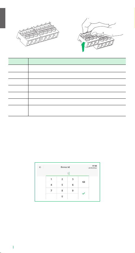
VEDO5TPR
000P1515XXXXXXXX
Centrale
Neutro
Fase
Terra