Comelit UT9279M User manual

TECHNICAL
MANUAL
Number keypad module Art. UT9279M
Passion.Technology.Design.
EN

2
Table of contents
Warning ............................................................................................ 2
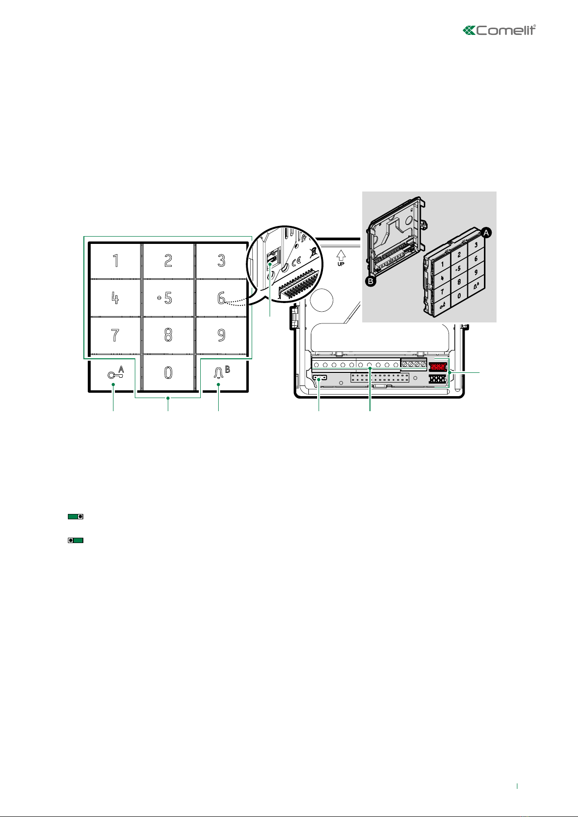
Description....................................................................................... 3
Technical specifications ................................................................. 4
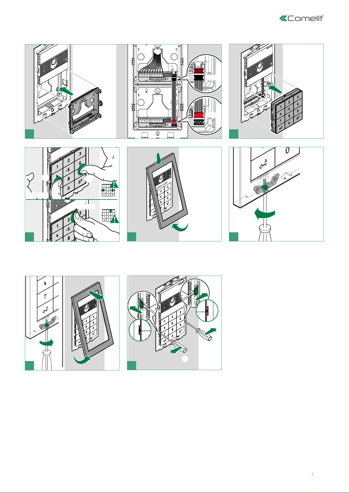
Installation........................................................................................ 5
Module removal........................................................................................5
Ultra audio/video module connection ........................................... 6
Stand-alone connection.................................................................. 7
Programming ................................................................................... 8
Default configuration ...............................................................................8
Indicator LED............................................................................................8
Changing the configuration.....................................................................8
Programming via number keypad.................................................. 9
Creating an access code.........................................................................9
Using an access code..............................................................................9
Deleting an access code .........................................................................9
Deleting all access codes........................................................................9
Use as a call module................................................................................9
Changing the supercode .........................................................................9
Programming general parameters........................................................10
Enabling/disabling the Buzzer ..............................................................10
Relay programming................................................................................11
Programming the clock input and key button.....................................11
Programming the universal access code ............................................11
Programming key backlighting.............................................................11
Changing relay settings.........................................................................12
Permanent activation of number keypad module backlight in stand-
alone mode .............................................................................................12
Restore factory settings........................................................................12
Programming via ViP Manager..................................................... 13
Connections available for programming via ViP Manager.................13
Searching for devices to configure ......................................................13
Populating the contacts list .................................................................14
System performance and layouts ................................................ 15
Warning
Intended use
This Comelit product has been designed and manufactured for use in the creation of audio and video communication
systems in residential, commercial, industrial and public buildings.
Installation
All activities connected to the installation of Comelit products must be carried out by qualified technical personnel,
with careful observation of the indications provided in the Manuals / Instruction sheets supplied with those products.
Wires
Disconnect the power supply before carrying out any operations on the wiring.
Use wires with a cross-section suited to the distances involved, observing the instructions provided in the system
manual.
We advise against running the system wires through the same duct as power cables (230V or higher).
Safe usage
To ensure Comelit products are used safely:
• carefully observe the indications provided in the Manuals / Instruction sheets,
• make sure the system created using Comelit products has not been tampered with / damaged.
Service
Comelit products do not require maintenance aside from routine cleaning, which should be carried out in accordance
with the indications provided in the Manuals / Instruction sheets.
Any repairs must be carried out:
• for the products themselves, exclusively by Comelit Group S.p.A.,
• for the systems, by qualified technical personnel.
Disclaimer
Comelit Group S.p.A. does not assume any responsibility for
• any purpose other than the intended use,
• failure to observe the indications and warnings contained in this Manual / Instruction sheet.
Comelit Group S.p.A. reserves the right to change the information provided in this Manual / Instruction Sheet at any
time and without prior notice.

1. 2. 3. 6.5.
4.
7.
3
Description
1. Key button
2. Number keypad
3. Bell key / status LED
4. Micro USB for connection to the computer
5. JP1 jumper for programming access
JP1 normal operation
JP1 programming mode active
6. Terminal block for connection:
RK local lock-release input
CK trade function input for key button enabling
GND negative for CK and RK
NO1 NC1 COM1
relay 1 contacts
NO2 COM2 relay 2 contacts
V- V+ 12-33 VDC or 12-24 VAC power supply input, for use in stand-alone mode (without Ultra audio or
audio/video module)
D1 D0 GND Wiegand output connection
IN Wiegand output command successful feedback
7. Connector for connecting previous/next modules
Module with number keypad for Ultra entrance panel, compatible with all systems. It can be used as a module for calling the
user directly when the code is known and for access control with the activation of built-in relays and audio or audio/video
module outputs, and system actuators. The access codes may be permanent (always valid), metered (valid for a certain number
of uses) or associated with a validity date. In the latter case, each code can be assigned a validity start/end date, dual daily
time band and validity days. Each access code can be assigned up to 4 different actions. The playback function for playing the
relevant audio message when each button is pressed can be enabled. There is also an event log, complete with all information
(activated codes, user that used them, users called, etc.), which can store up to 1275 events. It has a Wiegand output for
interfacing with access control systems. Automatic button backlight deactivation during daylight hours using the twilight sensor
for the paired audio or audio/video module. Anodised aluminium alloy coating. Dimensions: 100x90x35 mm (1 Ultra module).

4
Technical specifications
GENERAL DATA
Type Modular
Product height (mm) 90
Product width (mm) 100
Product depth (mm) 35
Product colour Aluminium
Material Polycarbonate, Anodised aluminium
Flush mounting Yes, with specific accessory
Surface mounting Yes, with specific accessory
COMPATIBLE SYSTEMS
Simplebus 2 audio/video with power supply unit art. 4888C Yes
Simplebus 2 audio/video with power supply unit art.
1210/1210A Yes
Simplebus 2 audio with power supply unit art. 1210/1210A Yes
Simplebus 1 audio Yes
ViP Yes
ELECTRICAL SPECIFICATIONS
Type of power supply Power supply via door entry monitor BUS,
External power supply
Power supply voltage 12-33 VDC, 12 VAC
Maximum absorption (W) 3.3
Absorption with 1 bistable relay activated (mA) 75
Absorption with 2 bistable relays activated (mA) 100
HARDWARE CHARACTERISTICS
Call type Digital
Type of buttons Mechanical
Number of buttons (no.) 12
Backlighting colour White, O
Terminals
RK CK GND NO1 NC1 COM1 NO2 COM2 V- V+ D1 D0 IN GND
Number of inputs (no.) 2
Number of outputs (no.) 2
ENVIRONMENTAL AND CONFORMITY SPECIFICATIONS
Operating temperature (°C) -25 to 55
Operating humidity (max RH - %) 25 to 95
Environmental class IV
Conformity and Certifications RoHS II - 2011/65/EU (EN 50581:2012), EMC 2014/30/EU
(EN 61000-6-1:2007, EN 61000-6-3:2007+A1:2011)
MAIN FUNCTIONS
Lock-release Yes
Voice synthesis Yes
System status visual indications Yes
Visual indications Yes
Acoustic indications Yes
Access control via lock-release code Yes
Number of auxiliary relays (no.) 2
Number of lock-release codes (no.) 4000

5
UP
BLACK
RED
Installation
1
2
1
1
3
2
4
4
2
2
CLOSE
5
CLACK!
CLACK!
12
3CLACK!
1
2
3
3
1
Module removal

6
Ultra audio/video module connection
UP
UP
UP
BLACK
RED
SIMPLEBUS1
2
SIMPLEBUS2
2
UT2010
UT2010VC
1210A
1210
UT2020
UT9279M
E
T
R
GND
SE
-SE
+
NO NC
C
O
M
LL
+
VV
-
UT8010
UT8020
GND
SE- SE+
NO NC
C
O
M
R
T
E
+
-
+
VV
- - -
TX TX
+
RX RX
+
UT9279M
UT1010
UT1010VC
UT1020
E
T
R
GND
SE NO NC
C
O
M
LL
+
VV
-
120-230 V
-
+
1595
UT9279M
1440

7
Stand-alone connection
1395 UT9279M
Art. 1595 can also be used.
Trade function input for enabling key button
Local lock-release input
Max 20 m. Local door-opener button.

8
Default configuration
PARAMETER DEFAULT VALUE
Supercode 778899 ◊
Number of characters for
opening codes 5
Relay paired with opening
*Module SE output **
Code validity 0 (permanent)
Relay 1 timing 2 seconds
Relay 1 buzzer Disabled
Relay 2 timing 2 seconds
Relay 2 buzzer Disabled
Panic function Disabled
Wiegand mode Disabled
(When enabled: every time
the button is pressed, its
code is emitted in 4 bits for
each digit without parity,
with the addition of the letter
“B” at the end of the string)
Backlighting Guided by the audio or
audio/video module (if
present) or always on (if
stand-alone) #
Maximum number of
errors 3
Playback of the relevant
audio message when each
button is pressed
Disabled
Type of system Simplebus
Buzzer Enabled
Clock input When the key button is
pressed, relay 1 is activated
Relay ringtone enabled Disabled
Universal access code (no pre-set code)
◊CAUTION: to guarantee security, we recommend
changing the supercode.
* Relay activated when a valid access code is recognised.
** To change the default setting, see: “Changing relay
settings”
# See: “Permanent backlight activation...”
If it is not changed, this is the configuration that will be
used when programming opening codes. Depending on
your requirements, you will always be able to change it
before programming these codes.
Indicator LED
The status LED is located behind the key. Indication
mode:
Flashing GREEN: code entry in progress
Steady RED: code rejected (active for 3 seconds)
Flashing RED: keypad locked due to an excessive number
of incorrect code entries. You need to wait 15 seconds
before you can enter a new code.
YELLOW: module in programming mode
Flashing BLUE: trade mode active
Changing the configuration
To change the configuration of the number keypad, you need
to enter programming mode.
To access programming, select one of the following modes:
• enter the Supercode on the number keypad
• set the Jumper (JP1) for the number keypad to
programming mode
• use the ViP Manager software, available to download free
of charge from the website pro.comelitgroup.com.
Programming

9
Creating an access code
1. For the default setting, enter the
first 5 characters of the supercode
» the LED lights up in yellow
77889
2. Enter a valid access code
(example: 98654)
the following are not permitted:
• codes shorter than the number
of characters required for access
codes (default 5)
• codes matching the supercode
(even partially)
• codes matching the universal
code
• codes containing the characters
A or B.
(code)
3. Confirm by pressing B
» if the code is correct: the LED
lights up in green for 3 seconds
» if the code is rejected: the LED
lights up in red for 3 seconds
4.
Wait for the LED to turn yellow
and repeat steps 2 and 3 to enter
other access codes
5. Press twice to exit
programming mode 2 ×
Using an access code
Enter the programmed access code
(example: 98654) to activate the paired
relay
» if the code is correct: the output is
activated and the LED lights up
in green for 3 seconds
» if the code is incorrect: the LED
lights up in red for 3 seconds
» if the maximum number of incorrect
code entry attempts is reached,
the keypad locks for 15 seconds
and the red LED flashes for the
duration of the lock period.
(code)
Deleting an access code
1. For the default setting, enter the
first 5 characters of the supercode
» the LED lights up in yellow
77889
2. Enter the access code you want to
delete (example: 98654)
(code)
3. Confirm by pressing A
4. Wait for the green LED to turn
yellow
5. Press twice to exit programming
mode 2 ×
Deleting all access codes
1. For the default setting, enter the first
5 characters of the supercode
» the LED lights up in yellow
77889
2. Enter the code BA0ABA
» the number keypad restarts, wait
20 seconds.
BA0ABA
Use as a call module
1. Enter the code for the internal unit
you want to call (example: 1) During
entry, the green LED flashes
(code)
2. Confirm by pressing B
» a call sent confirmation tone
sounds
The code can consist of up to 3 digits.
Changing the supercode
The new code should consist of 6 characters and must not
match the stores access codes, even partially.
1. For the default setting, enter the first
5 characters of the supercode
» the LED lights up in yellow
77889
2. Enter code B4
» the green LED flashes
3. Enter a new supercode
• it should be 6 characters long
the following are not permitted:
• codes matching the stored access
codes (even partially)
• codes matching the universal code
• codes containing the characters A
or B
(example: 578661)
During entry, the green LED flashes.
» if the code is correct: the LED
lights up in green for 3 seconds
» if the code is rejected: the LED
lights up in red for 3 seconds
(code)
4. Press twice to exit programming
mode 2 ×
Programming via number keypad

10
Programming general parameters
To change the general parameters, you will need to proceed
as follows:
CAUTION: you need to enter ALL the parameters, even
the ones you do not want to change
1. For the default setting, enter the first
5 characters of the supercode
» the LED lights up in yellow
77889
2. Enter code B0
» the green LED flashes
3. Enter the number of characters for
opening codes
This parameter is used to set the length of the
access codes [4-5-6].
Pre-set value: 5.
CAUTION: If this value is changed, all
previously programmed opening codes will be
deleted
choose
between
4-5-6
4. Enter the number corresponding to
the desired backlighting mode
[0] guided by the audio or audio/video module (if
present)
[1] timed
[2] always on (in stand-alone mode only)
In timed mode the backlighting switches o after
20 seconds of keypad inactivity.
Pre-set value: 0
choose
between
0-1-2
5. Enter 0 or 1 to disable or enable the
Panic function
This function is used to:
[1] activate relay 2 for the module to transmit an
instant alarm
[0] disable the function
Pre-set value: 0
choose
between
0-1
6. Select the Panic button
This function is used to select the Panic function,
entered after a valid access code, to activate
relay 2
Pre-set value: 3
CAUTION: Panic mode must be enabled. The
Panic character must be programmed even if
Panic mode is disabled
choose
between
1-2-3-4-5-6-
7-8-9-A-0-B
7. Enter the maximum number of
errors
The keypad locks when the maximum
programmed number of incorrect access codes
has been entered. You need to wait 15 seconds
before you can enter a new code.
Pre-set value: 3
choose
between
0-1-2-3-4-5-
6-7-8-9
8. Enter 0 or 1 to disable or enable
audio message playback when every
key is pressed
[1] enable
[0] disable
Pre-set value: 0
choose
between
0-1
9. Enter the number corresponding
to the type of system in which the
device is installed
[0] Simplebus
[2] IP (ViP)
Pre-set value: 0
choose
between
0-2
10. Set the buzzer volume
This function is used to select the sound level for
the buzzer: 0 minimum level, 9 maximum level.
Pre-set value: 9
choose
between
0-1-2-3-4-5-
6-7-8-9
11. Enter 0 or 1 to disable or enable
Wiegand mode
[1] enable
[0] disable
Pre-set value: 0
choose
between
0-1
12. Press twice to exit programming
mode 2 ×
EXAMPLE: restore the factory values for the general
parameters.
Enter supercode 77889
Enter code B0
Set the length of the opening code to 5
characters 5
Select the backlighting mode guided
by the audio/video module 0
Disable the Panic function 0
Set key 3 as Panic button 3
Set the maximum number of incorrect
access codes 3
Disable audio message playback when
keys are pressed 0
Set the Simplebus system type 0
Set the buzzer volume 9
Disable Wiegand mode 0
Exit programming 2 ×
Enabling/disabling the Buzzer
1. For the default setting, enter the first
5 characters of the supercode
» the LED lights up in yellow
77889
2. Enter code B80
» the green LED flashes
3. Enter 0 or 1 to disable or enable the
buzzer
While the buzzer function is enabled, the device
emits a tone every time a key is pressed
[1] enable
[0] disable
Pre-set value: 1
choose
between
0-1
4. Press twice to exit programming
mode 2 ×

11
Relay programming
1. For the default setting, enter the first
5 characters of the supercode
» the LED lights up in yellow
77889
2. Enter code B1 to program relay 1 or
enter code B2 to program relay 2
» the green LED flashes
or
3. Set the relay activation time (from 00
to 99 sec)
This function is used to set the activation time for
relay 1 or 2. An activation time between 01 and 99
seconds can be set.
If you want to set instant relay activation (with no
timing), set value 00
Pre-set value: 02 (2 seconds)
CAUTION: it is important to set both the tens
and the units for the activation time seconds,
even when you want to set a value under 10
seconds (for example: 09 sec)
00-01-02...
...98-99
4. Set the buzzer duration on activation
of the relay
This function is used to set the buzzer duration
when the relay is activated (from 0 to 9 seconds)
Pre-set value: 0 (buzzer disabled)
choose
between
0-1-2-3-4-5-
-6-7-8-9
5. Press twice to exit programming
mode 2 ×
Programming the clock input and key
button
This function uses the internal device clock (or an external
clock) to enable the key button to activate relay 1 in specific
time bands, or to authorise opening by means of an access
code in specific time bands only.
1. For the default setting, enter the first
5 characters of the supercode
» the LED lights up in yellow
77889
2. Enter code B81
» the green LED flashes
3. Enter the number corresponding to
the desired clock input operating
mode
[0] the clock input is ignored
[1] pressing the key button controls relay 1
[2] access codes are only authorised if the clock
input is enabled. The universal access code is
independent of the clock input and is always
authorised.
[3] Behaviour depends on the value of the “Relay
2” functions (see below)
Pre-set value: 1
choose
between
0-1-2-3
4. Enter the number corresponding
to the desired key button operating
mode
This parameter defines the role of the “Key”
button when the value of the “Clock Input”
parameter is set to “3”.
[0] function disabled
[1] pressing the “Key” button controls relay 2,
regardless of the Clock Input status
[2] pressing the “Key” button only controls relay 2
if the Clock Input is enabled.
Pre-set value: 0
choose
between
0-1-2
5. Press twice to exit programming
mode 2 ×
Programming the universal access code
If access code validity has been limited with the clock input, it
may be useful to have a “universal access code” for use in all
situations.
CAUTION: the universal access code must be 6 digits
long.
1. For the default setting, enter the first
5 characters of the supercode
» the LED lights up in yellow
77889
2. Enter code B82
» the green LED flashes
3. Enter a valid universal code
(example: 746541)
• it should be 6 characters long
the following are not permitted:
• codes matching the supercode
(even partially)
• codes matching the stored
access codes (even partially)
• codes containing the characters
A or B
(code)
4. Press twice to exit programming
mode 2 ×
Programming key backlighting
1. For the default setting, enter the first
5 characters of the supercode
» the LED lights up in yellow
77889
2. Enter code B83
» the green LED flashes
3. Set the desired brightness value
The value should be set between 000 and 100.
3 digits must always be entered. For example,
to set backlighting to 50% of the nominal value,
you need to enter 050.
example: 050
4. Press twice to exit programming
mode 2 ×

12
Changing relay settings
By default:
• the relay activated when a valid access code is
recognised is connected to the SE output for the audio or
audio/video module
• the codes are set as permanent
If the number keypad module is in stand-alone mode, or
if you want to change these parameters, you will need to
follow the procedure below:
1. For the default setting, enter the first
5 characters of the supercode
» the LED lights up in yellow
77889
2. Enter B5
3. Enter the number corresponding to
the output you want to activate
[1] keypad relay 1
[2] keypad relay 2
[3] keypad relay 1 and relay 2
[4] audio or audio/video module SE output
(default)
[5] audio or audio/video module relay 1
[6] External actuator
Pre-set value: 4
(number)
4. If you selected "6 = External actuator"
in step 2, enter the actuator address;
otherwise press 0
Pre-set value: 0
(address)
5. Set the opening code validity
[0] permanent, the access code is always valid
(default)
N [1 – 9] limit the number of code entries (e.g.: if
you select “5”, the code can be used 5 times, after
which it will be deleted)
Pre-set value: 0
(number of
uses)
6. Press twice to exit programming
mode 2 ×
CAUTION: From this moment all new stored access codes
will activate the configured output and will possess the
new set validity. Previously saved access codes remain
unchanged.
Permanent activation of number keypad
module backlight in stand-alone mode
1. For the default setting, enter the first
5 characters of the supercode
» the LED lights up in yellow
77889
2. Enter code B0
3. Enter the programming sequence
520330090
4. Press twice to exit programming
mode 2 ×
Restore factory settings
1. For the default setting, enter the first
5 characters of the supercode
» the LED lights up in yellow
77889
2. Enter the initialising code BA0BAB
» the number keypad restarts, wait 20
seconds.
BA0BAB

13
Programming via ViP Manager
The ViP Manager software used to program the number
keypad module using a computer is available on the website
pro.comelitgroup.com.
The main functions available are as follows:
• Access code entry. The access codes may be Permanent
(always valid), metered (valid for a certain number of uses)
or associated with a validity date. In the latter case, each
code can be assigned a validity start/end date, dual daily
time band and validity days.
• Each access code can be assigned up to 4 different
actions which will be carried out consecutively.
• Call code entry. The call function is enabled by default. It
can be disabled.
• Activation of playback of the corresponding audio
message when each button is pressed (e.g. if you press
2 on the number keypad, audio message “two” will be
played).
• Event log complete with all information (activated codes,
user that used them, users called, etc.). Up to 1275 events
can be saved in the memory.
• “Trade” function. On specific days of the week and
in specific time bands, simply pressing the key button
(without entering any code) will activate the output
associated with the keypad without an external clock.
Searching for devices to configure
√Connect the number keypad to the computer and open ViP Manager
In Options (1)/Local connections (2) select the Network interface (3).
Confirm by clicking OK (4).
Click Scan system (5) to start searching for devices.
Connections available for programming via ViP Manager
1210
1210A
1595
1440+1441

Name Access code
Antonio Rossi 824689
14
Populating the contacts list
1. Select Contacts/Contacts
2. Enter the information required (for each contact you need to enter at least one “access code”; enter the “Name” if you also
want to pair actions)
3. Press “Write page” to send the data to the number keypad module

www.comelitgroup.com
Via Don Arrigoni, 5 - 24020 Rovetta (BG) - Italy
CERTIFIED MANAGEMENT SYSTEMS
1st edition 01/2021
code 2G40002629
Other manuals for UT9279M
2
Table of contents
Other Comelit Keypad manuals

Comelit
Comelit DC60SS User manual

Comelit
Comelit IPKYBA02A User manual

Comelit
Comelit VEDO5TPR User manual

Comelit
Comelit UT9279M Owner's manual

Comelit
Comelit GSM-4IN User manual

Comelit
Comelit 3348B Owner's manual

Comelit
Comelit SKB User manual

Comelit
Comelit SKR User manual

Comelit
Comelit UT9279M User manual

Comelit
Comelit SKB User manual
Popular Keypad manuals by other brands

Satel
Satel INT-TSG Quick installation guide

Bosch
Bosch TouchOne user guide

Simons Voss Technologies
Simons Voss Technologies PIN code keypad MobileKey quick guide

Icy Box
Icy Box IB-289U3 user manual

LEGRAND
LEGRAND Vantage RK12E-A Series installation instructions

Radio Shack
Radio Shack 49-484 owner's manual