manuals.online logo
Brands
  1. Home
  2. •
  3. Brands
  4. •
  5. Comelit
  6. •
  7. Keypad
  8. •
  9. Comelit SKB User manual

Comelit SKB User manual

Passion.Technology.Design.
IT
MANUALE
TECNICO
EN
TECHNICAL
MANUAL
FR
MANUEL
TECHNIQUE
NL
TECHNISCHE
HANDLEIDING
DE
TECHNISCHES
HANDBUCH
ES
MANUAL
TÉCNICO
PT
MANUAL
TÉCNICO
IT
MANUALE
TECNICO
EN
TECHNICAL
MANUAL
FR
MANUEL
TECHNIQUE
NL
TECHNISCHE
HANDLEIDING
DE
TECHNISCHES
HANDBUCH
ES
MANUAL
TÉCNICO
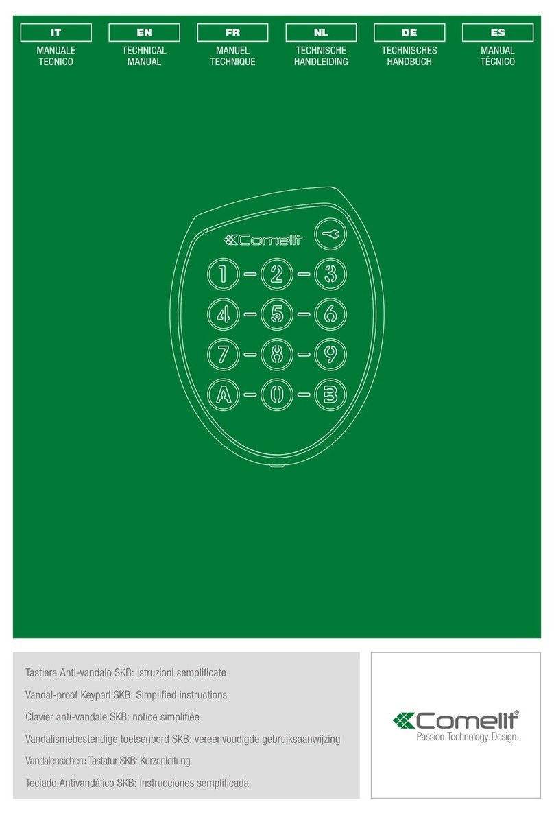
Tastiera Anti-vandalo SKB: Istruzioni semplificate
Vandal-proof Keypad SKB: Simplified instructions
Clavier anti-vandale SKB: notice simplifiée
Vandalismebestendige toetsenbord SKB: vereenvoudigde gebruiksaanwijzing
Vandalensichere Tastatur SKB: Kurzanleitung
Teclado Antivandálico SKB: Instrucciones semplificada
2
• Questo prodotto Comelit è progettato e realizzato con lo scopo di essere utilizzato
nella realizzazione di impianti per comunicazione audio e video in edifici residenziali,
commerciali, industriali e in edifici pubblici o ad uso pubblico.
• Tutte le attività connesse all’installazione dei prodotti Comelit devono essere
realizzate da personale tecnicamente qualificato, seguendo attentamente le
indicazioni di manuali / istruzioni dei prodotti stessi.
• Togliere l’alimentazione prima di effettuare qualsiasi operazione.
• Utilizzare conduttori con sezione adeguata in funzione delle distanze, rispettando le
indicazioni riportate nel manuale di sistema.
• Si consiglia di non posare i conduttori per l’impianto nella stessa tubazione dove
transitano i cavi di potenza (230V o superiori).
• Il presente documento riflette esclusivamente le indicazioni di base per l'utilizzo della
tastiera. Le istruzioni con la descrizione di tutte le funzioni sono disponibili sul nostro
sito pro.comelitgroup.com
• Per l’utilizzo sicuro dei prodotti Comelit è necessario seguire con attenzione le
indicazioni di manuali e istruzioni e curare che l’impianto realizzato con i prodotti
Comelit non sia manomesso o danneggiato.
• I prodotti Comelit non prevedono interventi di manutenzione ad eccezione delle
normali operazioni di pulizia, da effettuarsi comunque secondo quanto indicato in
manuali / istruzioni. Eventuali riparazioni devono essere effettuate: per i prodotti,
esclusivamente da COMELIT-IMMOTEC, per gli impianti, da personale tecnicamente
qualificato.
• COMELIT-IMMOTEC non assume alcuna responsabilità per usi differenti da
quello previsto e mancato rispetto di indicazioni ed avvertenze presenti in questo
manuale / istruzioni. COMELIT-IMMOTEC si riserva comunque il diritto di modificare
in qualsiasi momento e senza preavviso quanto descritto nel presente manuale /
istruzioni.
Avvertenze
• This Comelit product was designed for use in the creation of audio and video
communication systems in residential, commercial or industrial settings and in public
buildings or buildings used by the public.
• All activities connected to the installation of Comelit products must be carried out by
qualified technical personnel, with careful observation of the indications provided in
the manuals / instruction sheets supplied with those products.
• Cut off the power supply before carrying out any maintenance procedures.
• Use wires with a cross-section suited to the distances involved, observing the
instructions provided in the system manual.
• We advise against running the system wires through the same duct as the power
cables (230V or higher).
• This document only reflects the basic instructions for use of the key-pad. Further
details of all of its functions are available on our website pro.comelitgroup.com
• To ensure Comelit products are used safely: carefully observe the indications
provided in the manuals and make sure the system created using Comelit products
has not been tampered with / damaged.
• Comelit products do not require maintenance aside from routine cleaning, which
should be carried out in accordance with the indications provided in the manuals /
instruction sheets. Any repair work must be carried out: for the products themselves,
exclusively by COMELIT-IMMOTEC, for systems, by qualified technical personnel.
• COMELIT-IMMOTEC does not assume any responsibility for: any usage other than
the intended use; non-observance of the indications and warnings contained in this
manual / instruction sheet. COMELIT-IMMOTEC nonetheless reserves the right to
change the information provided in this manual / instruction sheet at any time and
without prior notice.
Warning
• Ce produit Comelit a été conçu et réalisé pour être utilisé dans la réalisation
d'installations de communication audio et vidéo dans des bâtiments résidentiels,
commerciaux, industriels et publics ou à usage public.
• Toutes les opérations liées à l'installation des produits Comelit sont réservées à des
techniciens qualifiés qui devront suivre attentivement les consignes des Manuels /
Instructions desdits produits.
• Couper l'alimentation avant d'effectuer toute opération.
• Utiliser des conducteurs d'une section adéquate en fonction des distances et en
respectant les explications contenues dans le manuel du système.
• Il est conseillé de ne pas poser les conducteurs destinés à l’installation dans la
canalisation destinée aux câbles de puissance (230 V ou plus).
• Ce document ne reflète que les indications de base pour l'utilisation du clavier. Une
notice, décrivant l'ensemble des fonctionnalités, est disponible sur notre site pro.
comelitgroup.com
• Pour utiliser les produits Comelit en toute sécurité : suivre attentivement les consignes
contenues dans les Manuels / Instructions; s'assurer que l’installation réalisée avec
les produits Comelit n'est pas sabotée / endommagée.
• Les produits Comelit sont sans maintenance, exception faite pour les opérations
de nettoyage qui devront être effectuées selon les consignes contenues dans les
Manuels / Instructions. Les réparations concernant : les produits, sont réservées
exclusivement à COMELIT-IMMOTEC, les installations, sont réservées à des
techniciens qualifiés.
• COMELIT-IMMOTEC ne sera pas tenue pour responsable en cas d'utilisation
contraire aux indications, de non-respect des indications et des recommandations
présentes dans ce Manuel / Instructions. COMELIT-IMMOTEC se réserve le droit
de modifier à tout moment et sans préavis le contenu de ce Manuel / Instructions.
Avertissements • Dit product van Comelit is ontworpen en ontwikkeld om te worden gebruikt bij de
realisatie van audio- en videocommunicatiesystemen In woningen, winkels, bedrijven
en openbare gebouwen of in openbare ruimtes.
• Alle functies die zijn aangesloten op de installatie van de Comelit-producten moeten
zijn uitgevoerd door gekwalificeerd technisch personeel, volgens de aanwijzingen in
de handleiding/instructies van de betreffende producten.
• Sluit de voeding af voordat u onderhoudswerkzaamheden uitvoert.
• Gebruik geleiders met een geschikte doorsnede, afhankelijk van de afstanden,
volgens de aanwijzingen in de handleiding van de installatie.
• Het is raadzaam om de kabels voor de installatie niet in dezelfde leiding te plaatsen als
die waar de vermogenskabels (230v of hoger) doorheen lopen.
• Dit document bevat enkel basisaanwijzingen voor het gebruik van het toetsenbord.
Op onze website pro.comelitgroup.com is een gebruiksaanwijzing beschikbaar waarin
alle functies gedetailleerd worden beschreven.
• Voor een veilig gebruik van de producten Comelit is het volgende noodzakelijk: het
zorgvuldig opvolgen van de aanwijzingen in de handleiding/instructies, ervoor zorgen
dat de installatie die met de Comelit-producten is uitgevoerd niet wordt gesaboteerd
/ beschadigd raakt.
• De producten van Comelit hebben geen onderhoud nodig, behalve de normale
reiniging, welke moet worden uitgevoerd zoals is aangegeven in de handleiding/
instructies. Eventuele reparaties moeten worden uitgevoerd voor de producten,
uitsluitend door COMELIT-IMMOTEC, voor de installatie, door gekwalificeerd
technisch personeel.
• COMELIT-IMMOTEC is niet verantwoordelijkheid voor andere toepassingen dan het
beoogde gebruik, het niet in acht nemen van de aanwijzingen en waarschuwingen
in deze handleiding/instructies. COMELIT-IMMOTEC behoudt zich het recht voor
om op elk moment, zonder waarschuwing vooraf, wijzigingen aan te brengen in deze
handleiding/instructies.
Waarschuwingen
• Dieses Comelit-Produktist für den Einsatz in Anlagen für Audio- und Video-
Kommunikation in Wohngebäuden, Gewerbe- und Industrieanlagen, in öffentlichen
Gebäuden und für den öffentlichen Gebrauch konzipiert.
• DieInstallationderComelit-Produkte darfnur durchFachkräfte untergenauer Befolgung
der Anweisungen in den technischen Handbüchern / den Bedienungsanleitungen
erfolgen.
• Vor Eingriffen an der Anlage immer die Spannungsversorgung unterbrechen.
• Leiter mit einem für die Entfernung bemessenen Querschnitt verwenden und die im
Handbuch der Anlage aufgeführten Anweisungen einhalten.
• Es wird empfohlen, die Leiter derAnlage nella nicht in den Rohren der Leistungskabel
(230 V oder höher) zu verlegen.
• Dieses Dokument enthält nur die grundsätzlichen Hinweise für die Benutzung der
Tastatur. Eine Anleitung für sämtliche Funktionen steht auf unserer Website pro.
comelitgroup.com zur Verfügung.
• Sicherer Umgang mit Comelit-Produkten: Halten Sie sich strikt an die Angaben
in den technischen Handbüchern / den Bedienungsanleitungen, Nehmen Sie
keine Änderungen an der Anlage mit Comelit-Produkten vor und vermeiden Sie
Beschädigungen.
• Die Comelit-Produkte erfordern keine Wartungsarbeiten, abgesehen von der normalen
Reinigung, die entsprechend den Anweisungen in den technischen Handbüchern /
den Bedienungsanleitungen auszuführen ist. Eventuelle Reparaturen dürfen für
die Produkte nur durch die Firma COMELIT-IMMOTEC, an der Anlage nur durch
Fachkräfte ausgeführt werden.
• COMELIT-IMMOTEC lehnt jede Haftung ab bei Schäden durch bestimmungsfremden
Gebrauch, Missachtung der Anweisungen und Hinweise in dem vorliegenden
technischen Handbuch / den Bedienungsanleitungen. COMELIT-IMMOTEC behält
sich vor, jeder Zeit und ohne Vorankündigung Änderungen an dem vorliegenden
technischen Handbuch / den Bedienungsanleitungen vorzunehmen.
Hinweise
• Este producto Comelit ha sido diseñado y realizado para usarse en instalaciones de
comunicación audio y vídeo tanto en edificios residenciales, comerciales e industriales
como en edificios públicos o de uso público.
• Todos los productos Comelit deben ser instalados por personal técnicamente
cualificado, siguiendo con atención las indicaciones de los manuales / las
instrucciones proporcionados con cada producto.
• Antes de efectuar cualquier operación hay que cortar la alimentación.
• Utilizar conductores de sección adecuada teniendo en cuenta las distancias y
respetando las instrucciones del manual de sistema.
• Se aconseja no colocar los conductores de la instalación en el mismo conducto
eléctrico por donde pasan los cables de potencia (230 V o superiores).
• Este documento solo refleja las indicaciones básicas para el uso del teclado. Puede
encontrar las instrucciones que detallan todas las funcionalidades en nuestra página
web pro.comelitgroup.com
• Para el uso seguro de los productos Comelit, es necesario seguir con atención
las indicaciones de los manuales / las instrucciones e garantizar que la instalación
realizada con los productos Comelit no pueda ser manipulada ni dañada.
• Los productos Comelit no prevén intervenciones de mantenimiento, salvo las normales
operaciones de limpieza, que se deben efectuar siempre según lo indicado en los
manuales / las instrucciones. Las reparaciones deben ser efectuadas: exclusivamente
por COMELIT-IMMOTEC cuando afecten a productos, por personal técnicamente
cualificado cuando afecten a instalaciones.
• COMELIT-IMMOTEC quedará libre de cualquier responsabilidad en caso de usos
diferentes a los previstos e incumplimiento de las indicaciones y advertencias
proporcionadas en el manual / las instrucciones. COMELIT-IMMOTEC se reserva
siempre el derecho de modificar en cualquier momento y sin preaviso el manual / las
instrucciones.
Advertencias
3
1 2 3 4 5 6 7 8
1 2 3 4 5 6 7 8
x8
2.
1.
1.
x3
x3
123
123
123
123
3.
2.
80 mm
20 mm
100 mm
1 2 3 4 5 6 7 8
1 2 3 4 5 6 7 8
x8
2.
1.
1.
x3
x3
123
123
123
123
3.
2.
80 mm
20 mm
100 mm
Il modulo SKB consente la programmazione di 100 codici apriporta
per la gestione dei relè 1 e 2. La digitazione sulla tastiera di un codice
apriporta aziona il relè associato. La corretta immissione del codice è
confermata dall'accensione del LED di stato.
VERDE = Relè 1 FUCSIA = Relè 2 BIANCO = Relè 1-2
L'immissione errata di un codice è segnalata dal LED ROSSO. Al terzo
tentativo di inserimento di un codice errato la tastiera si bloccherà per
15 secondi, durante i quali non sarà più possibile digitare nuovamente
il codice.
1. LED di stato
VERDE lampeggiante = Modalità immissione
GIALLO = Corretta immissione / Modalità programmazione
ROSSO = Errore di immissione
ROSSO lampeggiante = È necessario attendere 15 secondi prima di
poter ridigitare un codice.
ROSSO fisso: Modalità WIEGAND attiva. Ogni volta che un pulsante
viene premuto il suo codice viene emesso in 4 bit.
BLU = Modalità stand-by / Uscita dalla modalità programmazione
(BB) (No segnale acustico)
BLU lampeggiante: Orologio attivato »Tasto chiave operativo.
2. Tasto CHIAVE
Provoca l'apertura del Relè 1 se l'ingresso orologio è attivato.
The SKB module allows 100 opening codes to be programmed for
the management of relays 1 and 2. Entering an opening code on your
keypad will activate the corresponding relay. The status LED will light up
to confirm the code has been entered correctly.
GREEN = Relay 1 MAUVE = Relay 2 WHITE = Relay 1-2
If a code is entered incorrectly, the RED LED will light up. After the third
attempt at entering an incorrect code, the keypad will be locked for 15
seconds; it will not be possible to enter the code again during this period.
1. Status LED
Flashing GREEN = Input mode
YELLOW = Entry correct / Programming mode
RED = Entry error
Flashing RED = Wait 15 seconds before you can re-enter a code.
Permanent RED = WIEGAND Mode activated. Each time you press a
key, its code will be issued in 4 bits.
BLU = Standby mode / Leave programming mode (BB) (No audible
signal)
Flashing BLUE = Clock activated » Code key operational.
2. KEY button
Triggers the opening of Relay 1 if the clock entry is activated.
Descrizione
Description
Beschreibung
Le clavier SKB permet de programmer 100 codes d'ouverture pour la
gestion des relais 1 et 2. Tapez un code d'ouverture sur le clavier pour
actionner le relais associé. La LED d'état s'allume si le code a été saisi
correctement.
VERTE = Relais 1 MAUVE = Relais 2 BLANCHE = Relais 1-2
La LED ROUGE s'allume pour signaler que le code n'est pas correct.
Après la troisième tentative de saisie d'un code inexact, le clavier se
bloque 15 secondes durant lesquelles il sera impossible de taper le
code.
1. LED d'état
VERTE CLIGNOTANTE = Mode saisie
JAUNE = Saisie correcte / Mode programmation
ROUSSE = Saisie incorrecte
ROUSSE CLIGNOTANTE = Attendre 15s. avant de pouvoir ressaisir
un code.
ROUSSE PERMANENTE = Mode WIEGAND activé. A chaque appuie
sur une touche, son code sera émis en 4 bits.
BLEUE = Mode veille / Sortie du mode programmation (BB) (aucun
signal sonore)
BLEUE CLIGNOTANTE = Horloge activée »Touche clé opérationnel.
2. Touche Clé
Déclenche l’ouverture du Relais 1 si l’entrée horloge est activée.
Description
Met de SKB-module kunnen er 100 deurslot-bedieningscodes worden
geprogrammeerd voor het beheer van relais 1 en 2. Door een deurslot-
bedieningscode in te toetsen op het keypad wordt het daaraan
gekoppelde relais geactiveerd. De correcte invoer van de code wordt
bevestigd door het oplichten van de status-LED.
GROENE = Relais 1 PAARS = Relais 2 WITTE = Relais 1-2
Een verkeerde invoer van een code wordt gesignaleerd door de rode
led. Bij een derde mislukte poging om de code in te voeren, zal het
keypad 15 sec. geblokkeerd blijven. Het is dan niet mogelijk om de code
opnieuw in te toetsen.
1. Status-LED
GROENE KNIPPERENDE LED = Invoermodus
GELE LED = Correcte invoer / Programmeerstand
RODE LED = Foutieve invoer
RODE KNIPPERENDE LED = Wacht 15 seconden voordat u een
nieuwe code invoert.
RODE ONONDERBROKEN = WIEGAND-stand geactiveerd. Bij elke
druk op een toets, wordt een code van 4 bits uitgezonden.
BLAUWE LED = Waakstand / Programmeringsmodus verlaten (BB)
(Geen geluidssignaal)
BLAUW KNIPPERENDE LED = Klok geactiveerd »Sleuteltoets
operationeel.
2. Sleuteltoets
Opent Relais 1 als de klokingang is geactiveerd.
Beschrijving
Descripción
4
1 2 3 4 5 6 7 8
1 2 3 4 5 6 7 8
x8
2.
1.
1.
x3
x3
123
123
123
123
3.
2.
80 mm
20 mm
100 mm
Descrizione della parte posteriore
Das SKB-Modul ermöglicht die Programmierung von 100
Türöffnercodes für die Verwaltung der Relais 1 und 2. Die Eingabe eines
Türöffnercodes auf Ihrer Tastatur aktiviert das zugehörige Relais. Die
korrekte Eingabe des Codes wird durch die Status-LED bestätigt.
GRÜNE = Relais 1 LILA = Relais 2 WEISSE = Relais 1-2
Die rote LED zeigt an, dass ein Code falsch eingegeben wurde. Beim
dritten Versuch, einen falschen Code einzugeben, wird die Tastatur für 15
Sek. gesperrt, während dieser Zeit ist es nicht mehr möglich, den Code
erneut einzugeben.
1. Status-LED
GRÜNE LED BLINKEND = Eingabemodus
GELBE LED = Korrekte Eingabe / Programmiermodus
ROTE LED = Eingabefehler
ROTE LED BLINKEND = 15 Sekunden warten, bevor erneut ein Code
eingegeben werden kann.
ROTE LED LEUCHTEND = WIEGAND-Modus aktiviert. Bei jedem
Druck einer Taste wird der Code mit 4 Bits gesendet.
BLAUE LED = Ruhemodus / Programmiermodus verlassen (BB)
(Kein akustisches Signal)
BLAUE LED BLINKEND = Uhr aktiviert »Schlüsseltaste
einsatzbereit.
2. Schlüsseltaste
Löst die Öffnung des Relais 1 aus, wenn der Eingang Uhr aktiviert ist.
Description of the back
1. C2 (Brown) : Joint Relay 2
NC2 (Red) : NC Relay 2
NO2 (Orange) : NO Relay 2
H (Yellow) : Input Clock / Output Wiegand D1
D- (Green) : RS485 D-
D+ (Blue) : RS485 D+
GND (Violet) : GND
AL (Grey) : Output Alarm / Input Wiegand LED command
2. AL+ (White) Power supply: 12-35V DC or 12 - 24V AC
AL- (Black)
BP1 (Brown) : Input RTE / Output Wiegand D0
3. C1 (Red) : Joint Relay 1
NC1 (Orange) : NC Relay 1
NO1 (Yellow) : NO Relay 1
}
Description de la face arrière Achteraanzicht
1. C2 (Marrone) : Comune Relè 2
NC2 (Rosso) : NC Relè 2
NO2 (Arancio) : NO Relè 2
H (Giallo) : Ingresso Orologio / Uscita Wiegand D1
D- (Verde) : RS485 D-
D+ (Blu) : RS485 D+
GND (Viola) : GND
AL (Grigio) : Uscita Allarme / Ingresso Wiegand comando LED
2. AL+ (Bianco) Alimentazione 12-35V CC o 12 - 24V CA
AL- (Nero)
BP1 (Marrone) : Ingresso RTE / Uscita Wiegand D0
3. C1 (Rosso) : Comune Relè 1
NC1 (Arancio) : NC Relè 1
NO1 (Giallo) : NO Relè 1
}
Darstellung der Rückseite Descripción de la parte trasera
El módulo SKB permite programar 100 códigos abrepuertas para
gestionar los relés 1 y 2. Cuando en el teclado se marca un código
abrepuertas, se acciona el relé que se le ha asociado. La introducción
correcta del código se confirma mediante el encendido del LED de
estado.
VERDE = Relé 1 MALVA = Relé 2
BLANCO = Relés 1-2
La introducción errónea de un código se indica mediante el encendido
del LED rojo. Tras el tercer intento, si se introduce de nuevo un código
erróneo, el teclado se bloquea por 15 segundos durante los cuales no
es posible marcar el código otra vez.
1. LED de estado
VERDE PARPADEANTE = Modo introducción
AMARILLO = Introducción correcta / Modo de programación
ROJO = Introducción errónea
ROJO intermitente = Esperar 15 seg. antes de volver a introducir un
código.
ROJO permanente = Modo WIEGAND activado. Cada vez que pulse
una tecla, se emitirá su código en 4 bits.
AZUL = Modo vigilia / Salida del modo de programación (BB) (sin
señal acústica)
AZUL intermitente: Reloj activado »Tecla llave operativa.
2. Tecla llave
Activa la apertura del Relé 1 si la entrada reloj está activada.
5
1. C2 (Marron) : Commun Relais 2
NC2 (Rouge) : NC Relais 2
NO2 (Orange) : NO Relais 2
H (Jaune) : Entrée Horloge / Sortie Wiegand D1
D- (Vert) : RS485 D-
D+ (Bleu) : RS485 D+
GND (Violet) : GND
AL (Gris) : Sortie Alarme / Entrée Wiegand commande LED
2. AL+ (Blanc) Alimentation 12 - 35V DC ou 12 - 24V AC
AL- (Noir)
BP1 (Marron) : Entrée BP1 / Sortie Wiegand D0
3. C1 (Rouge) : Commun Relais 1
NC1 (Orange) : NC Relais 1
NO1 (Jaune) : NO Relais 1
}}
1. C2 (Bruin) : Gemeenschappelijk relais 2
NC2 (Rood) : NC Relais 2
NO2 (Oranje) : NO Relais 2
H (Geel) : Klokingang / Uitgang Wiegand D1
D- (Groen) : RS485 D-
D+ (Blauw) : RS485 D+
GND (Paars) : GND
AL (Grijs) : Alarmuitgang / Ingang Wiegand LED driver
2. AL+ (Wit) Voeding 12-35V DC of 12 - 24V AC
AL- (Zwart)
BP1 (Bruin) : Ingang RTE / Uitgang Wiegand D0
3. C1 (Rood) : Gemeenschappelijk Relais 1
NC1 (Oranje) : NC Relais 1
NO1 (Geel) : NO Relais 1
1. C2 (Braun) : Gemeinsames Kabel Relais 2
NC2 (Rot) : NC Relais 2
NO2 (Orange) : NO Relais 2
H (Gelb) : Eingang Uhr / Ausgang Wiegand D1
D- (Grün) : RS485 D-
D+ (Blau) : RS485 D+
GND (Violett) : Erdung
AL (Grau) : Ausgang Alarm / Eingang Wiegand Steuerung LED
2. AL+ (Weiß) Stromversorgung 12-35 V DC oder 12-24 V AC
AL- (Schwarz)
BP1 (Braun) : Eingang RTE / Ausgang Wiegand D0
3. C1 (Rot) : Gemeinsames Kabel Relais 1
NC1 (Orange) : NC Relais 1
NO1 (Gelb) : NO Relais 1
}
1. C2 (Marrón) : Común Relé 2
NC2 (Rojo) : NC Relé 2
NO2 (Naranja) : NO Relé 2
H (Amarillo) : Entrada Reloj / Salida Wiegand D1
D- (Verde) : RS485 D-
D+ (Azul) : RS485 D+
GND (Violeta) : GND
AL (Gris) : Salida Alarma / Entrada Wiegand control LED
2. AL+ (Blanc) Alimentación 12-35 V DC o 12 - 24V AC
AL- (Negro)
BP1 (Marrón) : Entrada RTE / Salida Wiegand D0
3. C1 (Rojo) : Común Relé 1
NC1 (Naranja) : NC Relé 1
NO1 (Amarillo) : NO Relé 1
}
+
-
SKB
C2
NC2
NO2
C1
NC1
NO1
H
D-
D+
GND
AL
AL+
AL-
BP1
BP (RTE)
CABLAGGIO con dispositivo di blocco a emissione
AANDACHT: Als er een sluitingssysteem van het type
schootplaat of zuignap wordt gebruikt, zorg ervoor dat
de bijgeleverde varistor is aangesloten om storingen te
voorkomen.
Het BP-contact kan worden verbonden met GND of AL-
In caso di utilizzo di una serratura elettrica o una serratura
magnetica, accertatevi che il varistore ricevuto in dotazione con
la vostra tastiera sia raccordato in modo tale da evitarne un
possibile malfunzionamento.
Potete collegare il contatto del pulsante di uscita sia al
morsetto AL- che al morsetto GND
WIRING with door controller
CAUTION: When you use a lock or shutter type closing
system, check that the varistance supplied with your keyboard
is connected to avoid any malfunction.
You can connect the RTE button contact to both the AL-
terminal and the GND terminal
CABLAGE avec gâche à émission
ATTENTION : Dans le cas d’une utilisation d’un système
de fermeture type gâche ou ventouse, veillez à ce que la
varistance fournie avec votre clavier soit raccordée pour éviter
tout dysfonctionnement de celui-ci.
Vous pouvez connecter le contact du BP soit au GND soit au AL-
BEKABELING met slot
VERKABELUNG mit Arbeitsstrom-Türöffner
Wenn Sie ein Schließsystem mit Schließklappe oder
Sauger verwenden, achten Sie darauf, dass der zusammen
mit Ihrer Tastatur gelieferte Varistor angeschlossen ist, um
Funktionsstörungen der Tastatur zu vermeiden.
Der BP-Kontakt kann mit GND oder AL- verbunden werden
CABLEADO con cerradero
En caso de uso de un sistema de cierre tipo pestillo o
ventosa, asegúrese de que se ha conectado el varistor que se
suministra con el teclado para evitar cualquier tipo de fallo por
parte de este.
Se puede conectar el contacto del botón de salida tanto al
terminal AL- y al terminal GND
6
Configurazione predefinita
• Codice master: 123456
• Lunghezza codici: 5 caratteri
• Relè associato all'apertura: N°1
• Temporizzazione relè N°1: 5 secondi
• Cicalino Relè N°1: disattivato
• Indirizzo Logico: 001
• Modalità Anti-Aggressione: disattivato
• Modalità Wiegand: disattivato
• Modalità Relè: interno
• Retroilluminazione: permanente
• Cicalino: disattivato
Questa è la configurazione che verrà utilizzata durante la programmazione dei
codici di apertura. In base alle vostre esigenze è sempre possibile modificarla
prima della programmazione.
Codice master
ll codice master permette di accedere alla programmazione dell'articolo.
A seconda della configurazione del numero di caratteri della vostra tastiera
verrà utilizzato in parte o per intero. (Paragrafo "Lunghezza codici")
Per esempio, se viene mantenuta la configurazione di default a 5 caratteri,
occorrerà utilizzare solo le prime 5 cifre del codice master per accedere alla
programmazione.
È possibile cambiare il codice di default "123456". Il nuovo codice:
• deve avere una lunghezza di 6 caratteri
• può contenere numeri e lettere
Procedere come di seguito:
1. Per impostazione di default, digitare i primi 5 caratteri del
codice master 12345
2. Digitare B4
3. Inserire un codice di 6 cifre (Esempio 778899) (Codice)
4. » Attendere che il LED da verde fisso diventi giallo ...
5. Uscire dalla modalità di programmazione BB
Lunghezza codici
La tastiera di default è configurata per l'inserimento di codici a 5 caratteri,
codice master compreso. È possibile modificare la lunghezza dei codici da un
minimo di 3 caratteri fino ad un massimo di 6.
Se questa impostazione viene modificata, tutti i codici apriporta
precedentemente programmati veranno eliminati.
Procedere come di seguito:
3 CIFRE 4 CIFRE 5 CIFRE 6 CIFRE
1. 12345 12345 12345 12345
2. B0 B0 B0 B0
3. 300000 400000 500000 600000
4. » Attendere che il LED da verde fisso diventi giallo
5. BB BB BB BB
Programmazione codici apriporta (Default relè 1)
SKB di default attribuisce ai codici apriporta le caratteristiche elencate in
"Configurazione predefinita". (Vedi sopra).
• Non è possibile programmare codici che iniziano con il tasto "B".
• Non è possibile programmare un codice apriporta uguale al
codice master.
1. Per impostazione di default, digitare i primi 5 caratteri del
codice master
12345
2. Inserire un codice di apertura valido (Esempio 55555) (Codice)
3. Digitare B
4. » Attendere che il LED da verde fisso diventi giallo ...
5. Uscire dalla modalità di programmazione BB
È possibile velocizzare la procedura: arrivati al punto 4 ripetere i passi fatti
dal punto 2 al punto 5.
Scelta del relè
SKB di default associa i
codici di apertura
al relè 1; per modificare questa
impostazione procedere come di seguito:
RELÈ 1 RELÈ 2 RELÈ 1 e 2
1. 12345 12345 12345
2. B5 B5 B5
3. 10 20 30
4. » Attendere che il LED da verde fisso diventi giallo
5. (Codice) (Codice) (Codice)
6. BBB
7. » Attendere che il LED da verde fisso diventi giallo
8. BB BB BB
Tempo di apertura del relè
La temporizzazione dei relè di default è di 05 secondi. È possibile modificare il
tempo da un minimo di 01 secondi fino ad un massimo di 99 secondi.
Per modificare questa impostazione procedere come da esempi:
RELÈ 1, 1 SEC. RELÈ 2, 99 SEC.
1. 12345 12345
2. B1 B2
3. 010 Tempo 990
4. » Attendere che il LED da verde fisso diventi giallo
5. BB BB
Cancellazione codici apriporta
Cancellazione singoli codici
1. Per impostazione di default, digitare i primi 5 caratteri del
codice master
12345
2.
Digitare il codice che si desidera eliminare
(Codice)
3. Digitare A
4. » Attendere che il LED da verde fisso diventi giallo ...
5. Uscire dalla modalità di programmazione BB
In caso di eliminazione di più codici è possibile velocizzare la procedura:
arrivati al punto 4 ripetere i passi fatti dal punto 2 al punto 5.
Cancellazione totale
1. Per impostazione di default inserire solo 5 caratteri del
codice master
12345
2. Digitare B0A
3. » Attendere che il LED da verde fisso diventi giallo ...
4. Uscire dalla modalità di programmazione BB
Ripristino della configurazione predefinita
In caso di modifica dei parametri predefiniti è sempre possibile ripristinarli.
Il ripristino allo stato di fabbrica non cancella i codici di apertura già
programmati. Tuttavia, se la configurazione precedente prevedeva un numero
di caratteri diverso da 5, tutti i codici di apertura precedentemente programmati
verranno eliminati.
1. Per impostazione di default, digitare i primi 5 caratteri del
codice master
12345
3. Digitare BA0BAB
4. » Attendere che il LED da verde fisso diventi giallo ...
5. Uscire dalla modalità di programmazione BB
Istruzioni complete al sito pro.comelitgroup.com > SKB > Manuali
Tastiera SKB
7
Default configuration
• Master code: 123456
• Code length: 5 characters
• Relays associated with opening: No. 1
• Time delay for relay number 1: 5 seconds
• Buzzer for relay number 1: off
• Logic address: 001
• Anti-aggression mode: off
• Wiegand mode: off
• Relay mode: internal
• Backlighting: permanent
• Buzzer: off
This is the configuration used during the programming of opening codes.
Depending on your requirements, you will always be able to change it before
programming begins.
Master code
The master code grants authorisation to program the product.
Depending on how the number of characters on your keypad is set up, it will be
used partially or in full. (“Code length” section)
For example, if you keep the default configuration of 5 characters, only the
first 5 digits of the master code will be required to access programming mode.
The default code "123456” can be changed. The new code:
• must be 6 characters long
• must contain both numbers and letters
Proceed as follows:
1. For the default setting, enter the first 5 characters of the
master code 12345
2. Enter B4
3. Enter a 6 digit code (Example: 778899) (Code)
4. » Wait for the steady green LED to turn yellow ...
5. Exit programming mode BB
Code length
The default configuration requires the entry of codes with 5 characters,
including the master code. The length of the codes can be adjusted to a
minimum of 3 characters, up to a maximum of 6.
If this setting is changed, all opening codes programmed previously will
be deleted.
Proceed as follows:
3 DIGITS 4 DIGITS 5 DIGITS 6 DIGITS
1. 12345 12345 12345 12345
2. B0 B0 B0 B0
3. 300000 400000 500000 600000
4. » Wait for the steady green LED to turn yellow
5. BB BB BB BB
Programming opening codes (Default relay 1)
SKB by default assigns the characteristics listed in "Default configuration” to
the opening codes. (See above).
• Codes starting with “B” cannot be programmed.
• It is not possible to program an opening code which is the same as
the master code.
1. For the default setting, enter the first 5 characters of the
master code
12345
2. Enter a valid opening code (Example: 55555) (Code)
3. Enter B
4. » Wait for the steady green LED to turn yellow ...
5. Exit programming mode BB
You can speed this procedure up: once you have reached step 4, repeat
steps 2 to 5.
Choosing the relay
SKB by default links the
opening codes
to relay 1; to change this setting,
proceed as follows:
RELAY 1 RELAY 2 RELAYS 1 and 2
1. 12345 12345 12345
2. B5 B5 B5
3. 10 20 30
4. » Wait for the steady green LED to turn yellow
5. (Code) (Code) (Code)
6. B B B
7. » Wait for the steady green LED to turn yellow
8. BB BB BB
Relay opening time
The relay timer is set by default to 05 seconds. The time period can be adjusted
to a minimum of 01 seconds, up to a maximum of 99.
To change this setting, proceed as illustrated by the examples:
RELAY 1, 1 SEC. RELAY 2, 99 SEC.
1. 12345 12345
2. B1 B2
3. 010 Time 990
4. » Wait for the steady green LED to turn yellow
5. BB BB
Deleting opening codes
Deleting individual codes
1. For the default setting, enter the first 5 characters of the
master code
12345
2.
Enter the code you wish to delete
(Code)
3. Enter A
4. » Wait for the steady green LED to turn yellow ...
5. Exit programming mode BB
If you want to delete several codes, you can speed this procedure up: once
you have reached step 4, repeat steps 2 to 5.
Delete all
1. For the default setting, enter only 5 characters of the
master code
12345
2. Enter B0A
3. » Wait for the steady green LED to turn yellow ...
4. Exit programming mode BB
Restoring the default configuration
If you are changing default parameters, it will always be possible to restore
them.
Restoring the factory setting does not delete the opening codes you
have already programmed. However, if the previous configuration specified
a number of characters other than 5, all the opening codes programmed
previously will be deleted.
1. For the default setting, enter the first 5 characters of the
master code
12345
3. Enter BA0BAB
4. » Wait for the steady green LED to turn yellow ...
5. Exit programming mode BB
Full instructions: pro.comelitgroup.com > SKB > Manuals
SKB keypad
8
Configuration générale
• Code maître : 123456
• Nombre de termes : 5
• Relais associé à l'ouverture : N°1
• Temporisation Relais N°1 : 5 secondes
• Buzzer Relais N°1 : Désactivé
• Adresse logique : 001
• Mode Anti-Agression : Désactivé
• Mode Wiegand : Désactivé
• Mode Relais : Interne
• Rétro-éclairage : Permanent
• Buzzer : Désactivé
C'est cette configuration qui sera utilisée lors de la programmation des codes
d'ouverture. Selon vos besoins, vous avez toujours la possibilité de la modifier
avant la programmation.
Code maître
Le code maître donne l'autorisation de programmer le clavier.
Selon la définition du nombre de termes de votre clavier, son utilisation sera
partielle ou totale. (Paragraphe « Nombre de termes »)
Par exemple, si votre clavier est défini en 5 termes (valeur usine), il ne
faudra utiliser que les 5 premiers termes du code maître pour accéder à la
programmation.
Il est possible de modifier la valeur d'usine « 123456 ». Le nouveau code :
• devra compter 6 termes au maximum
• peut contenir des chiffres et des lettres
Procédez de la façon suivante :
1. Par défaut, tapez les 5 premiers termes du code maître. 12345
2. Tapez B4
3. Tapez un code de 6 chiffres (par exemple 778899) (Code)
4. » Attendez que la LED verte passe au jaune ...
5. Sortez du mode Programmation BB
Nombre de termes
Le clavier d'origine est configuré pour saisir des codes à 5 termes, code maître
compris. Il est possible de modifier le nombre de termes en passant d'un
minimum de 3 à un maximum de 6.
Si cette valeur est modifiée, tous les codes d'ouverture précédemment
programmés seront supprimés.
Procédez de la façon suivante :
3 CHIFFRES 4 CHIFFRES 5 CHIFFRES 6 CHIFFRES
1. 12345 12345 12345 12345
2. B0 B0 B0 B0
3. 300000 400000 500000 600000
4. » Attendez que la LED verte passe au jaune
5. BB BB BB BB
Programmation codes d'ouverture (Relais 1 par défaut)
SKB attribue par défaut aux codes d'ouverture, les caractéristiques indiquées
dans « Configuration générale ». (Voir ci-dessus).
• Il n'est pas possible de programmer des codes d'ouverture
commençant par la touche « B ».
• Il n'est pas possible de programmer un code d'ouverture identique
au code maître.
1. Par défaut, tapez les 5 premiers termes du code maître. 12345
2. Tapez un code d'ouverture correct (par exemple 55555) (Code)
3. Tapez B
4. » Attendez que la LED verte passe au jaune ...
5. Sortez du mode Programmation BB
Il est possible d'accélérer la procédure : une fois arrivés au point 4, répéter
les étapes du point 2 au point 5.
Choix du relais
SKB associe par défaut les
codes d'ouverture
au relais 1 ; pour modifier cette
configuration, procédez de la façon suivante :
RELAIS 1 RELAIS 2 RELAIS 1 et 2
1. 12345 12345 12345
2. B5 B5 B5
3. 10 20 30
4. » Attendez que la LED verte passe au jaune
5. (Code) (Code) (Code)
6. BBB
7. » Attendez que la LED verte passe au jaune
8. BB BB BB
Temps d'ouverture du relais
Par défaut, la temporisation des relais correspond à 5 secondes. Il est possible
de modifier le temps d'un minimum de 1 seconde à un maximum de 99
secondes.
Pour modifier cette valeur, procédez selon les exemples suivants :
RELAIS 1, 1 SECONDE RELAIS 2, 99 SECONDES
1. 12345 12345
2. B1 B2
3. 010 Temps 990
4. » Attendez que la LED verte passe au jaune
5. BB BB
Effacement des codes d'ouverture
Effacement de chaque code
1. Par défaut, tapez les 5 premiers termes du code maître. 12345
2.
Tapez le code que vous souhaitez effacer.
(Code)
3. Tapez A
4. » Attendez que la LED verte passe au jaune ...
5. Sortez du mode Programmation BB
En cas d'effacement de plusieurs codes, il est possible d'accélérer la
procédure : une fois arrivés au point 4, répéter les étapes du point 2 au point 5.
Effacement total
1. Par défaut, tapez uniquement 5 termes du code maître. 12345
2. Tapez B0A
3. » Attendez que la LED verte passe au jaune ...
4. Sortez du mode Programmation BB
Réinitialisation de la configuration générale
Il est possible de revenir à la configuration générale lorsque celle-ci a été
modifiée.
La réinitialisation usine n'efface pas les codes d'ouverture déjà
programmés. Néanmoins, si la précédente configuration comportait un
nombre de termes différents de 5, tous les codes d'ouverture précédemment
programmés seront supprimés.
1. Par défaut, tapez les 5 premiers termes du code maître. 12345
3. Tapez BA0BAB
4. » Attendez que la LED verte passe au jaune ...
5. Sortez du mode Programmation BB
Instructions complètes sur le site pro.comelitgroup.com > SKB > Manuels
Clavier SKB
9
Voorgedefinieerde configuratie
• Master-code: 123456
• Lengte codes: 5 tekens
• Relais gekoppeld aan de opening: Nr. 1
• Tijdsinstelling relais nr. 1: 5 seconden
• Zoemer relais nr. 1: gedeactiveerd
• Logisch adres: 001
• Anti-agressiemodus: gedeactiveerd
• Wiegand-modus: gedeactiveerd
• Relais-modus: intern
• Achtergrondverlichting: permanent
• Zoemer: gedeactiveerd
Dit is de configuratie die wordt gebruikt tijdens de programmering van de
deurslot-bedieningscodes. Afhankelijk van uw wensen, is het altijd mogelijk
deze voor de programmering te wijzigen.
Master-code
De master-code geeft toegang tot de programmering van het artikel.
Afhankelijk van de configuratie van het aantal tekens op uw keypad, wordt de
code geheel of gedeeltelijk gebruikt. (Paragraaf "Lengte codes")
Als bijvoorbeeld de standaard configuratie met 5 tekens behouden blijft, dan
hoeven alleen de eerste 5 cijfers van de master-code te worden gebruikt om
toegang te krijgen tot de programmering.
Het is mogelijk de standaard code "123456” te wijzigen. De nieuwe code:
• moet 6 tekens lang zijn
• kan uit cijfers en letters bestaan
Ga als volgt te werk:
1. Voor de standaard instelling voert u de eerste 5 tekens van
de master-code in 12345
2. Toets in B4
3. Voer een 6-cijferige code in (Bijvoorbeeld 778899) (Code)
4. » Wacht totdat de groene led geel oplicht ...
5. De programmeringsmodus verlaten BB
Lengte codes
Het standaard keypad is geconfigureerd voor het invoeren van 5-cijferige
codes, inclusief master-code. Het is mogelijk de lengte van de codes te
wijzigen van minimaal 3 tekens tot maximaal 6 tekens.
Als deze instelling wordt gewijzigd, worden alle eerder geprogrammeerde
deurslot-bedieningscodes verwijderd.
Ga als volgt te werk:
3 CIJFERS 4 CIJFERS 5 CIJFERS 6 CIJFERS
1. 12345 12345 12345 12345
2. B0 B0 B0 B0
3. 300000 400000 500000 600000
4. » Wacht totdat de groene led geel oplicht
5. BB BB BB BB
Programmering deurslot-bedieningscodes (standaard relais 1)
Standaard SKB kent aan de deurslot-bedieningscodes de eigenschappen toe
vermeld in "Voorgedefinieerde configuratie". (Zie hierboven).
• Het is niet mogelijk codes te programmeren die beginnen met de
toets "B".
• Het is niet mogelijk een deurslot-bedieningscode te programmeren
die gelijk is aan de master-code.
1. Voor de standaard instelling voert u de eerste 5 tekens van
de master-code in
12345
2. Voer een geldige deurslot-bedieningscode in (Bijvoorbeeld
55555) (Code)
3. Toets in B
4. » Wacht totdat de groene led geel oplicht ...
5. De programmeringsmodus verlaten BB
De procedure kan worden versneld: aangekomen bij punt 4 herhaalt u de
stappen vanaf punt 2 tot en met 5.
Relais kiezen
De standaard SKBkoppelt de
deurslot-bedieningscodes
aan relais 1; om deze
instelling te wijzigen gaat u als volgt te werk:
RELAIS 1 RELAIS 2 RELAIS 1 EN 2
1. 12345 12345 12345
2. B5 B5 B5
3. 10 20 30
4. » Wacht totdat de groene led geel oplicht
5. (Code) (Code) (Code)
6. B B B
7. » Wacht totdat de groene led geel oplicht
8. BB BB BB
Openingstijd van het relais
De tijdsinstelling van het standaard relais bedraagt 5 seconden. Het is mogelijk
de tijd te wijzigen van minimaal 01 seconde naar maximaal 99 seconden.
Om deze instelling te wijzigen, volgt u de voorbeelden:
RELAIS 1, 1 SEC. RELAIS 2, 99 SEC.
1. 12345 12345
2. B1 B2
3. 010 Tijd 990
4. » Wacht totdat de groene led geel oplicht
5. BB BB
Wissen van deurslot-bedieningscodes
Afzonderlijke codes wissen
1. Voor de standaard instelling voert u de eerste 5 tekens van
de master-code in
12345
2.
Toets de code in die u wilt verwijderen
(Code)
3. Toets in A
4. » Wacht totdat de groene led geel oplicht ...
5. De programmeringsmodus verlaten BB
Bij het verwijderen van meerdere codes kan de procedure worden versneld:
aangekomen bij punt 4 herhaalt u de stappen vanaf punt 2 tot en met 5.
Alles wissen
1. Voor de standaard instelling voert u alleen de 5 tekens van
de master-code in
12345
2. Toets in B0A
3. » Wacht totdat de groene led geel oplicht ...
4. De programmeringsmodus verlaten BB
Voorgedefinieerde configuratie herstellen
Bij het wijzigen van de voorgedefinieerde parameters, is herstel van de
oorspronkelijke parameters altijd mogelijk.
Bij het herstellen van de fabrieksparameters worden de eerder
geprogrammeerde deurslot-bedieningscodes gewist. Ook als de vorige
configuratie iets anders dan 5 tekens bevatte, worden alle eerder
geprogrammeerde deurslot-bedieningscodes verwijderd.
1. Voor de standaard instelling toets u de eerste 5 tekens van
de master-code in
12345
3. Toets in BA0BAB
4. » Wacht totdat de groene led geel oplicht ...
5. De programmeringsmodus verlaten BB
Volledige instructies zijn te vinden op de site pro.comelitgroup.com > SKB
> Handleidingen
Keypad SKB
10
Vordefinierte Konfiguration
• Mastercode: 123456
• Codelänge: 5 Zeichen
• Mit der Öffnung verbundenes Relais: Nr. 1
• Zeitverzögerung Relais Nr. 1: 5 Sekunden
• Summer Relais Nr. 1: Deaktiviert
• Logische Adresse: 001
• Einbruchsschutz-Modus: Deaktiviert
• Wiegand-Modus: Deaktiviert
• Relais-Modus: Intern
• Hintergrundbeleuchtung: Permanent
• Summer: Deaktiviert
Diese Konfiguration wird bei der Programmierung der Öffnungscodes
verwendet. Abhängig von Ihren Bedürfnissen haben Sie stets die Möglichkeit,
sie vor Programmierung der Codes zu ändern.
Mastercode
DerMastercodeermöglichtIhnendenZugriffaufdieProgrammierungdesArtikels.
Je nach Konfiguration wird die Anzahl der Zeichen Ihrer Tastatur teilweise oder
vollständig verwendet. (Paragraph „Codelänge“)
Wenn beispielsweise die standardmäßige 5-stellige Konfiguration beibehalten
wird, müssen Sie nur die ersten 5 Ziffern des Mastercodes verwenden, um auf
die Programmierung zuzugreifen.
Der Standardcode „123456“ kann geändert werden. Der neue Code:
• muss eine Länge von 6 Zeichen haben
• kann Zahlen und Buchstaben enthalten
Gehen Sie wie folgt vor:
1. Als Standardeinstellung die ersten 5 Zeichen des
Mastercodes eingeben. 12345
2. Eingeben B4
3. Einen 6-stelligen Code eingeben (Beispiel 778899) (Code)
4. » Warten Sie, bis die LED gelb und nicht mehr grün leuchtet ...
5. Programmiermodus verlassen BB
Codelänge
Die Standardtastatur ist für die Eingabe von 5-stelligen Codes, einschließlich
des Mastercodes, programmiert. Die Länge der Codes kann von mindestens 3
Zeichen auf maximal 6 Zeichen geändert werden.
Wird diese Einstellung geändert, werden alle zuvor programmierten
Türöffnercodes gelöscht.
Gehen Sie wie folgt vor:
3 ZEICHEN 4 ZEICHEN 5 ZEICHEN 6 ZEICHEN
1. 12345 12345 12345 12345
2. B0 B0 B0 B0
3. 300000 400000 500000 600000
4. » Warten Sie, bis die LED gelb und nicht mehr grün leuchtet
5. BB BB BB BB
Programmierung von Türöffnercodes (Standardrelais 1)
Standardmäßig ordnet SKB den Türöffnern die unter „Vordefinierte
Konfiguration“ aufgeführten Merkmale zu. (Siehe oben).
• Es ist nicht möglich, Codes zu programmieren, die mit der Taste
„B“ beginnen.
• Es ist nicht möglich, einen Türöffnercode zu programmieren, der
dem Mastercode entspricht.
1. Als Standardeinstellung die ersten 5 Zeichen des
Mastercodes eingeben.
12345
2. Einen gültigen Öffnungscode eingeben (Beispiel 55555) (Code)
3. Eingeben B
4. » Warten Sie, bis die LED gelb und nicht mehr grün leuchtet ...
5. Programmiermodus verlassen BB
Der Vorgang kann beschleunigt werden: Sobald Sie Punkt 4 erreicht
haben, wiederholen Sie die Schritte von Punkt 2 bis Punkt 5.
Auswahl des Relais
Standardmäßig ordnet SKB die Öffnungscodes dem Relais 1 zu; um diese
Einstellung zu ändern, gehen Sie wie folgt vor:
RELAIS 1 RELAIS 2 RELAIS 1 und 2
1. 12345 12345 12345
2. B5 B5 B5
3. 10 20 30
4. » Warten Sie, bis die LED gelb und nicht mehr grün leuchtet
5. (Code) (Code) (Code)
6. B B B
7. » Warten Sie, bis die LED gelb und nicht mehr grün leuchtet
8. BB BB BB
Öffnungszeit des Relais
Die voreingestellte Zeitsteuerung der Relais beträgt 05 Sekunden. Die Dauer
kann von mindestens 01 Sekunde auf maximal 99 Sekunden geändert werden.
Verfahren Sie wie in den Beispielen gezeigt, um diese Einstellung zu ändern:
RELAIS 1, 1 SEC. RELAIS 2, 99 SEC.
1. 12345 12345
2. B1 B2
3. 010 Zeit 990
4. » Warten Sie, bis die LED gelb und nicht mehr grün leuchtet
5. BB BB
Löschen der Türöffnungscodes
Löschen einzelner Codes
1. Als Standardeinstellung die ersten 5 Zeichen des
Mastercodes eingeben.
12345
2.
Geben Sie den Code ein, den Sie löschen möchten.
(Code)
3. Eingeben A
4. » Warten Sie, bis die LED gelb und nicht mehr grün leuchtet ...
5. Programmiermodus verlassen BB
Wenn mehr als ein Code gelöscht wird, kann der Vorgang beschleunigt
werden: Sobald Sie Punkt 4 erreicht haben, wiederholen Sie die Schritte von
Punkt 2 bis Punkt 5.
Vollständiges Löschen
1. Als Standardeinstellung nur 5 Zeichen des Mastercodes
eingeben.
12345
2. Eingeben B0A
3. » Warten Sie, bis die LED gelb und nicht mehr grün leuchtet ...
4. Programmiermodus verlassen BB
Rücksetzung der vordefinierten Konfiguration
Bei einer Änderung der vordefinierten Parameter, können diese immer wieder
zurückgesetzt werden.
Das Zurücksetzen auf die Werkseinstellungen löscht die bereits
programmierten Öffnungscodes nicht. Wenn die vorherige Konfiguration jedoch
eine andere Anzahl von Zeichen als 5 hatte, werden alle zuvor programmierten
Öffnungscodes gelöscht.
1. Als Standardeinstellung die ersten 5 Zeichen des
Mastercodes eingeben.
12345
3. Eingeben BA0BAB
4. » Warten Sie, bis die LED gelb und nicht mehr grün leuchtet ...
5. Programmiermodus verlassen BB
Ausführliche Anweisungen unter pro.comelitgroup.com > SKB >
Handbücher.
SKB Tastatur
11
Configuración predefinida
• Código maestro: 123456
• Longitud de los códigos: 5 caracteres
• Relé asociado a la apertura: N.° 1
• Temporización del relé N.° 1: 5 segundos
• Zumbador del relé N.° 1: desactivado
• Dirección lógica: 001
• Modo antiagresiones: desactivado
• Modo Wiegand: desactivado
• Modo relé: interno
• Retroiluminación: permanente
• Zumbador: desactivado
Esta es la configuración que se utilizará durante la programación de los
códigos de apertura. En función de las exigencias del usuario, siempre es
posible modificarla antes de la programación.
Código maestro
El código maestro permite acceder a la programación del artículo.
Según el número de caracteres configurado en el teclado, se utilizará todo el
código o bien solo una parte (apartado "Longitud de los códigos").
Por ejemplo, si se mantiene la configuración por defecto de 5 caracteres, para
acceder a la programación solo se deberán utilizar los 5 primeros dígitos del
código maestro.
Es posible cambiar el código por defecto "123456". El nuevo código:
• debe tener una longitud de 6 caracteres
• puede contener números y letras
Efectuar las operaciones descritas a continuación:
1. Para la configuración por defecto, marcar los 5 primeros
caracteres del código maestro 12345
2. Marcar B4
3. Introducir un código de 6 dígitos (por ejemplo, 778899) (Código)
4. » Esperar a que el led pase de color verde fijo a amarillo ...
5. Salir del modo de programación BB
Longitud de los códigos
Por defecto, el teclado está configurado para introducir códigos de 5
caracteres, incluido el código maestro. Es posible modificar la longitud de los
códigos desde un mínimo de 3 caracteres hasta un máximo de 6.
Si se modifica esta configuración, todos los códigos abrepuertas
programados anteriormente se eliminarán.
Efectuar las operaciones descritas a continuación:
3 DÍGITOS 4 DÍGITOS 5 DÍGITOS 6 DÍGITOS
1. 12345 12345 12345 12345
2. B0 B0 B0 B0
3. 300000 400000 500000 600000
4. » Esperar a que el led pase de color verde fijo a amarillo
5. BB BB BB BB
Programación de los códigos abrepuertas (por defecto, relé 1)
Por defecto, SKB atribuye a los códigos abrepuertas las características
indicadas en "Configuración predefinida" (véase más arriba).
• No es posible programar códigos que empiecen con la tecla "B".
• No es posible programar un código abrepuertas igual al código
maestro.
1. Para la configuración por defecto, marcar los 5 primeros
caracteres del código maestro
12345
2. Introducir un código de apertura válido (por ejemplo,
55555) (Código)
3. Marcar B
4. » Esperar a que el led pase de color verde fijo a amarillo ...
5. Salir del modo de programación BB
Es posible agilizar el procedimiento: al llegar al punto 4, repetir los pasos
realizados desde el punto 2 hasta el punto 5.
Selección del relé
Por defecto, SKB asocia los
códigos de apertura
al relé 1; para modificar esta
configuración, efectuar las operaciones descritas a continuación:
RELÉ 1 RELÉ 2 RELÉS 1 y 2
1. 12345 12345 12345
2. B5 B5 B5
3. 10 20 30
4. » Esperar a que el led pase de color verde fijo a amarillo
5. (Código) (Código) (Código)
6. BBB
7. » Esperar a que el led pase de color verde fijo a amarillo
8. BB BB BB
Tiempo de apertura del relé
Por defecto, la temporización de los relés es de 5 segundos. Es posible
modificar el tiempo desde un mínimo de 1 segundos hasta un máximo de 99
segundos.
Para modificar esta configuración, realizar las operaciones descritas en los
ejemplos:
RELÉ 1, 1 s. RELÉ 2, 99 s.
1. 12345 12345
2. B1 B2
3. 010 Tiempo 990
4. » Esperar a que el led pase de color verde fijo a amarillo
5. BB BB
Borrado de los códigos abrepuertas
Borrado de un código
1. Para la configuración por defecto, marcar los 5 primeros
caracteres del código maestro
12345
2.
Marcar el código que se desea eliminar
(Código)
3. Marcar A
4. » Esperar a que el led pase de color verde fijo a amarillo ...
5. Salir del modo de programación BB
Si se desea eliminar varios códigos, es posible agilizar el procedimiento: al
llegar al punto 4, repetir los pasos realizados desde el punto 2 hasta el punto 5.
Borrado total
1. Para la configuración por defecto, introducir solo los 5
caracteres del código master
12345
2. Marcar B0A
3. » Esperar a que el led pase de color verde fijo a amarillo ...
4. Salir del modo de programación BB
Restablecimiento de la configuración predefinida
En caso de modificación de los parámetros predefinidos, siempre es posible
restablecerlos.
El restablecimiento según la configuración de fábrica no borra los códigos
de apertura ya programados. De todas formas, si la configuración precedente
preveía un número de caracteres diferente a 5, todos los códigos de apertura
programados anteriormente se eliminarán.
1. Para la configuración por defecto, marcar los 5 primeros
caracteres del código maestro
12345
3. Marcar BA0BAB
4. » Esperar a que el led pase de color verde fijo a amarillo ...
5. Salir del modo de programación BB
Instrucciones completas en el sitio pro.comelitgroup.com > SKB >
Manuales.
Teclado SKB
5ª edizione 01/2019
cod. 2G40002357
www.comelitgroup.com
Via Don Arrigoni, 5 - 24020 Rovetta (BG) - Italy
CERTIFIED MANAGEMENT SYSTEMS
[FULL MANUAL]
Installazione su una parete Installazione su cartongesso
Wall installation Installation on plasterboard
Installation sur un mur Installation sur une plaque de plâtre
Installatie op een muur Installatie op een gipsplaat
Befestigung an der Wand Befestigung an einer Gipsplatte
Instalación en una pared Instalación en una placa de yeso

Other manuals for SKB

1

Other Comelit Keypad manuals

Comelit UT9279M User manual

Comelit

Comelit UT9279M User manual

Comelit SKR User manual

Comelit

Comelit SKR User manual

Comelit IPKYBA02A User manual

Comelit

Comelit IPKYBA02A User manual

Comelit VEDO5TPR User manual

Comelit

Comelit VEDO5TPR User manual

Comelit UT9279M Owner's manual

Comelit

Comelit UT9279M Owner's manual

Comelit UT9279M User manual

Comelit

Comelit UT9279M User manual

Comelit 3348B Owner's manual

Comelit

Comelit 3348B Owner's manual

Comelit DC60SS User manual

Comelit

Comelit DC60SS User manual

Comelit SKB User manual

Comelit

Comelit SKB User manual

Comelit GSM-4IN User manual

Comelit

Comelit GSM-4IN User manual

Popular Keypad manuals by other brands

A-Neuvideo ANI-8WP instruction manual

A-Neuvideo

A-Neuvideo ANI-8WP instruction manual

RCI 9325 quick start

RCI

RCI 9325 quick start

Gemini GEM-RP8 operating guide

Gemini

Gemini GEM-RP8 operating guide

Gecko in.k800 Quick reference card

Gecko

Gecko in.k800 Quick reference card

Crestron CNWM-10A user guide

Crestron

Crestron CNWM-10A user guide

MCM Electronics ICON 16 Series user guide

MCM Electronics

MCM Electronics ICON 16 Series user guide

Conlan Mykey CP1000 user manual

Conlan

Conlan Mykey CP1000 user manual

Bosch TouchOne user guide

Bosch

Bosch TouchOne user guide

Velux KLI 110 Simple setup guide

Velux

Velux KLI 110 Simple setup guide

Satel INT-SK-GR manual

Satel

Satel INT-SK-GR manual

Satel INT-TSG2 user manual

Satel

Satel INT-TSG2 user manual

MCS MCS-DOOR-KEYPAD manual

MCS

MCS MCS-DOOR-KEYPAD manual

Protection One 6148PL2 installation guide

Protection One

Protection One 6148PL2 installation guide

Radionics D206 installation instructions

Radionics

Radionics D206 installation instructions

CDVI GALEO 4.0 - Bluetooth installation manual

CDVI

CDVI GALEO 4.0 - Bluetooth installation manual

First Alert FA560VKP Installation and setup guide

First Alert

First Alert FA560VKP Installation and setup guide

NetworX NX-148E user manual

NetworX

NetworX NX-148E user manual

Delta Electronics Digital Keypad / Display ASD-PU-01B instruction sheet

Delta Electronics

Delta Electronics Digital Keypad / Display ASD-PU-01B instruction sheet

manuals.online logo
manuals.online logoBrands
  • About & Mission
  • Contact us
  • Privacy Policy
  • Terms and Conditions

Copyright 2025 Manuals.Online. All Rights Reserved.