Comelit Simplebus Color 4888C User manual

Simplebus 2 Mixer/Power Supply Unit
Art. 4888C
EN
TECHNICAL
MANUAL
FREE DOWNLOAD
MYCOMELIT, L'APP PER IL PROFESSIONISTA
MYCOMELIT: THE APP FOR PROFESSIONALS

2 3
Power supply unit for audio or audio/video systems with 1 input compatible with all outdoor entrance panels featuring
Simplebus 1 technology and 4 outputs for the connection of up to 100 devices such as door-entry phones and door entry
monitors featuring Simplebus 2 technology.
It is equipped with an LED to signal any short-circuits detected on the lines and an AC output facility for powering additional
devices such as switching devices art. 1224A, 1424 and/or actuator relay art. 1256.
Allows intercom functions between users. Equipped with 4 line termination terminals art. 1216.
Dimensions (L x H x D): 140 x 140 x 67 mm (8 DIN modules).
Description
1. -+17.5 VDC (±5%)/100 mA max. Output for power supply Art.1224A, Art.1424 , Art.1256.
2. JP1 Jumper to be set according to the total number of users connected to the mixer/power supply Art.4888C.
3. L1 L1 riser branch output 1
L2 L2 riser branch output 2
L3 L3 riser branch output 3
L4 L4 riser branch output 4.
4. Terminal protection
5. DL1 indicator LED.
Continuous flashing: indicates an extended short-circuit on one of the mixer outputs.
6. JP5 for video closure if several 4888C products are connected in cascade
7. Lin Lin connection to the line originating from the external entrance panel.
8. JP4 device reset.
9. JP2 Jumper to be set according to the total number of users connected to the mixer/power supply Art.4888C.
10. LN ~230 V~. Mains alternating: 230 VAC (+15/-10%) 50/60 Hz/0.7 A.
terminal to be connected to the earthing system.
JP1
1 2 3
JP2
321
3
2
1476
59
10
JP4
12
8
DL1
Warning ............................................................................................ 2
Description....................................................................................... 3
Specifications .................................................................................. 4
Installation........................................................................................ 5
Wire ducts.................................................................................................5
Connections..................................................................................... 6
Programming ................................................................................... 6
Configuring number of users via Jumpers JP1 AND JP2.....................6
Auto-configuration reset via Jumper JP4..............................................6
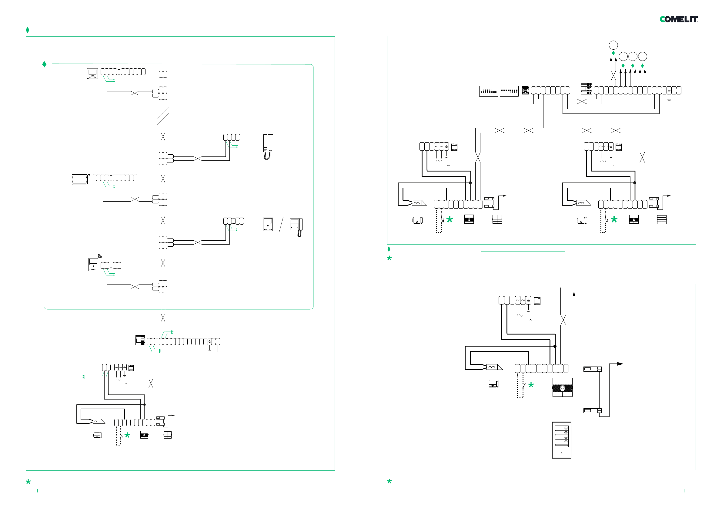
System performance and layouts .................................................. 7
Operating distances ..................................................................................8
Example of maximum expansion per apartment.........................................9
Apartment block variant with 1 to 4 risers with 2 entrance panels ....11
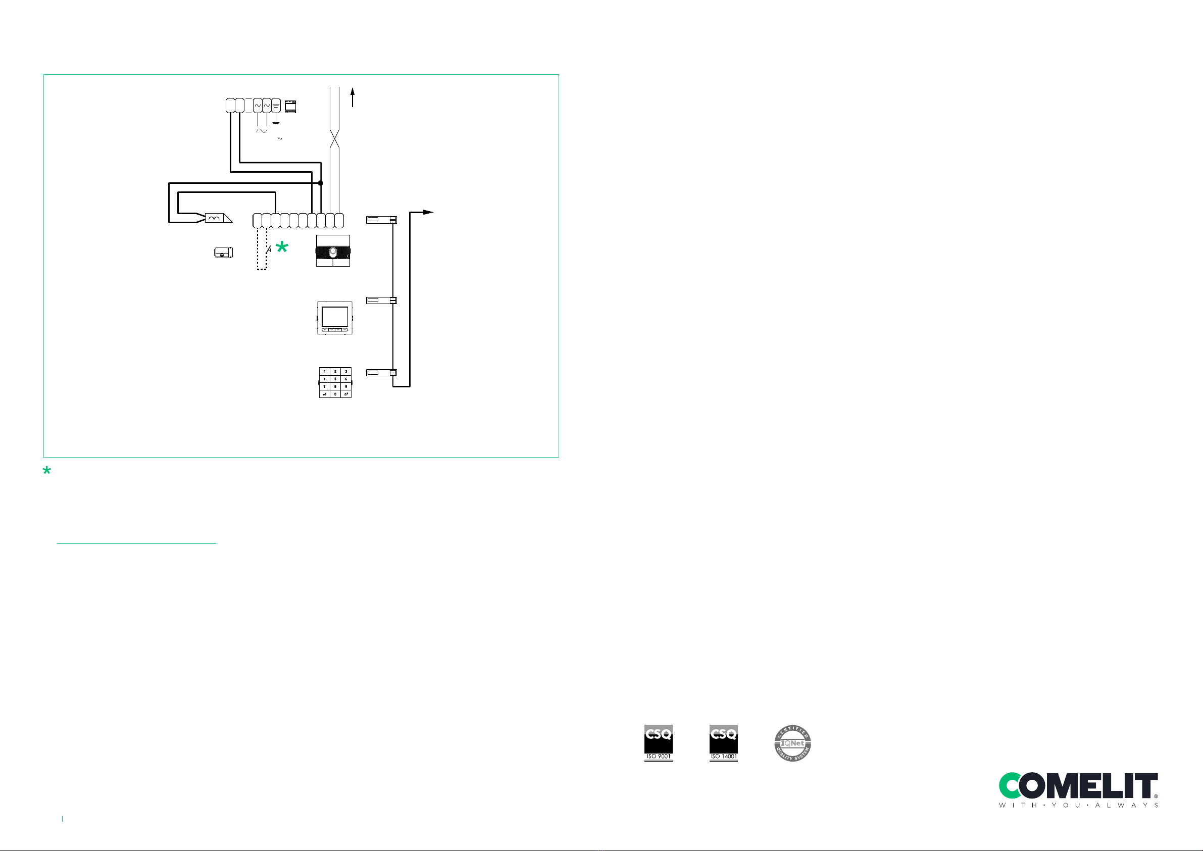
Digital Entrance Panel Variant with Touch-screen module Art. UT927011
Digital Entrance Panel Variant with number keypad module Art.
UT9279M, UT9279MB, UT9279MW and directory Art. UT9260M ........12
Table of contents
Warning
Intended use
This Comelit product has been designed and manufactured for use in the creation of audio and video communication
systems in residential, commercial, industrial and public buildings.
Installation
All activities connected to the installation of Comelit products must be carried out by qualified technical personnel, with
careful observation of the indications provided in the Manuals / Instruction sheets supplied with those products.
Wires
Disconnect the power supply before carrying out any operations on the wiring.
Use wires with a cross-section suited to the distances involved, observing the instructions provided in the system manual.
We advise against running the system wires through the same duct as power cables (230V or higher).
Safe usage
To ensure Comelit products are used safely:
• carefully observe the indications provided in the Manuals / Instruction sheets,
• make sure the system created using Comelit products has not been tampered with / damaged.
Service
Comelit products do not require maintenance aside from routine cleaning, which should be carried out in accordance with
the indications provided in the Manuals / Instruction sheets.
Any repairs must be carried out:
• for the products themselves, exclusively by Comelit Group S.p.A.,
• for the systems, by qualified technical personnel.
Disclaimer
Comelit Group S.p.A. does not assume any responsibility for
• any purpose other than the intended use,
• non-observance of the indications and warnings contained in this Manual / Instruction sheet.
Comelit Group S.p.A. reserves the right to change the information provided in this Manual / Instruction Sheet at any time
and without prior notice.
Directives/standards
• The manufacturer, Comelit Group S.p.A., hereby declares that the equipment art. 4888C conforms to directives 2014/30/
EU and 2014/35/EU. The full EU conformity declaration is available at the following web address:
https://pro.comelitgroup.com/en-gb/product/4888c
• This product falls within the scope of European product directive 2012/19/UE concerning the management of waste
electrical and electronic equipment (WEEE). The device should not be disposed of as unsorted domestic waste as it
consists of various materials which can be recycled at relevant premises. Contact your local authority to find out the
location of the environmental companies best suited to receiving the product for disposal and subsequent proper
recycling. The product is not potentially harmful to human health, as it does not contain toxic substances as specified in
Directive 2011/65/EU (RoHS), but if abandoned in the natural environment may negatively impact the ecosystem. Read
the instructions carefully before using the product for the first time. We advise against using the product for any purpose
other than its intended use, as improper use may present the risk of electric shocks.
This symbol on the product label indicates that the product complies with the standards concerning
waste electrical and electronic equipment. Improper use of the equipment, or abandoning it in the natural
environment, may be punished by law.

4 5
Installation
Appliance exclusively for indoor use.
High voltage, proceed with caution.
Install inside a closed electrical panel so that it may only be accessed by authorised personnel.
A suitable omnipolar switch with a contact opening of at least 3 mm must be installed upstream of the
video entry phone system.
• Disconnect the power supply before carrying out any operations on the wiring.
• Replace the protections on the terminals.
• Do not obstruct the ventilation and cooling slits or openings.
Wire ducts
• If it is necessary to run (even for short distances) sections of cable entering the mixer Art. 4888C (section SIMPLEBUS
1) through the same ducting as sections exiting the mixer Art. 4888C (section SIMPLEBUS 2), always use separate
sheathed cables.
• If it is necessary to run (even for short distances) sections of cable exiting the mixer Art. 4888C (section SIMPLEBUS 2)
through the same ducting, always use separate sheathed cables.
• Do not use pairs other than the specified multipolar cable
• Do not use loose cables
SIMPLEBUS 1
SIMPLEBUS 2
4888C
4888C4888C 4888C4888C
SIMPLEBUS 2
4888C
SIMPLEBUS 1
SIMPLEBUS 2 SIMPLEBUS 2 SIMPLEBUS 2 SIMPLEBUS 2
Specifications
MAIN FEATURES
Power supply voltage 230 VAC / 50-60 Hz
Input connector Terminal block
Applicable to DIN rail Yes
Number of DIN modules (no.) 8
HARDWARE SPECIFICATIONS
Product weight (g) 800
GENERAL DATA
Height (mm) 67
Width (mm) 140
Depth (mm) 140
Coating material type Makrolon 9425
Product colour WHITE RAL9010
Operating temperature (°C) - 5 - 40
Operating humidity (max. RH) (%( 25 - 95
COMPATIBILITY
Simplebus 2 audio/video system Yes
MOUNTING/INSTALLATION
Surface mounting Yes
ELECTRICAL SPECIFICATIONS
Maximum current absorption (mA) 700

6 7
System performance and layoutsConnections
Programming
Configuring number of users via Jumpers JP1 AND JP2
Systems with 0 to 15 users Systems with 16 to 35 users Systems with 36 to 100 users
JP1 JP2
1 2 3
1 2 3
JP1
123
JP2
123
JP1
123
JP2
123
Auto-configuration reset via Jumper JP4
12
JP4
12
JP4
1. Set JP4 to position 1 to cancel auto-
configuration of the item.
2. If LED DL1 is lit steadily, this
indicates that the cancellation
procedure has been successful.
3. Reset JP4 to position 2 (factory
setting) and check that LED DL1
switches o
4888C
H
1214/2C
1216
6721W
6721W/BM
+6710
6601W
6601W/BM
(MAX 3)
6601W
6601W/BM
4833C
4888C
1214/2C
1216
6721W
6721W/BM
+6710
B
A
F
C
D
A
F
I
4888C
4834/9 E
6701W
6701W/8
6701W/BM
+6710
6801W
6801W/BM
6801W
6801W/BM
1200
UT1020
UT1020
UT1020
6701W
6701W/8
6701W/BM
+6710
I
4888C
~~
230V
18VDC
L
4
L
2
L
3
L
1
L
2
L
3
L
4
L
IN
L
IN
L
1
~
-
+
1 2 3 4
VIDEO ENTRY SYSTEM RISERS
OUTPUT FOR POWER SUPPLY
Art.1224A / 1424 / 1256
EXTERNAL UNIT

98
Example of maximum expansion per apartment
1214/2C
1214/2C
Art. 6701W-6701W/8
Art. 6741W
Art. 6801W
Art. 6721W
Art. 6801W
Art. 6601W
Art. 6601W
1214/2C
1214/2C
1214/2C
1214/2C
4888C
CV1
CV2
CV1
CV2
1214/2C
6741W 6721W 6721W 6721W
G
CV1
CV2
CV1
CV2
G
A MAX B MAX C MAX D MAX E MAX F MAX G MAX H MAX I MAX Art.1216
Comelit Art.4577/4579
1 mm²
(Ø 1.2 mm AWG 17)
200 m
(650
feet)
200 m
(650
feet)
200 m
(650
feet)
200 m
(650
feet)
150 m
(490
feet)
50 m
(165
feet)
50 m
(165 feet)
100 m
(330
feet)
2
1
UTP5 cat. 5 0.2 mm²
(Ø 0.5 mm AWG 24)
80 m
(260
feet)
150 m
(490
feet)
150 m
(490
feet)
150 m
(490
feet)
100 m
(330
feet)
60 m
(195
feet)
2
1
0.28 mm²
(Ø 0.6 mm AWG 23)
100 m
(330
feet)
150 m
(490
feet)
150 m
(490
feet)
150 m
(490
feet)
100 m
(330
feet)
5 m
(15 feet)
10 m
(30 feet)
60 m
(195
feet)
2
1
0.5 mm²
(Ø 0.8 mm AWG 20)
120 m
(395
feet)
100 m
(330
feet)
100 m
(330
feet)
100 m
(330
feet)
80 m
(260
feet)
25 m
(85 feet)
25 m
(82 feet)
60 m
(195
feet)
2
1
1 mm²
(Ø 1.2 mm AWG 17) 120 m
(395
feet)
150 m
(490
feet)
150 m
(490
feet)
150 m
(490
feet)
80 m
(260
feet)
50 m
(165
feet)
50 m
(165 feet)
60 m
(195
feet)
30 m
(98 feet)
2
1
1 mm²
(Ø 1.2 mm AWG 17)
120 m
(395
feet)
80 m
(260
feet)
80 m
(260
feet)
80 m
(260
feet)
50 m
(165
feet)
50 m
(165
feet)
50 m
(165 feet)
40 m
(130
feet)
2
1
1.5 mm²
(Ø 1.4 mm AWG 15)
150 m
(490
feet)
100 m
(330
feet)
100 m
(330
feet)
100 m
(330
feet)
80 m
(260
feet)
75 m
(245
feet)
100 m
(330 feet)
60 m
(195
feet)
50 m
(164
feet)
2
1
2.5 mm²
(Ø 1.8 mm AWG 13)
150 m
(490
feet)
100 m
(330
feet)
100 m
(330
feet)
100 m
(330
feet)
80 m
(260
feet)
100 m
(330
feet)
150 m
(490
feet)
60 m
(195
feet)
Operating distances
B
A
F
H
1214/2C
1595
1216
6741W
6741W/BM + 6710
4888C
UT1020
S3
DIP 1
I
Compatible secondary door entry monitors: 6701W (/BM), 6701W/8, 6721W (/BM), 6801W (/BM), 6601W (/BM)

10 11
L
OUT
L
IN
L
IN
L
OUT
1214/2C
22-28 Vdc
L
OUT
L
IN
L
IN
L
OUT
1214/2C
LM
LM
C
F
P
LL
C
F
P
12
1 2 3 4 5 6
6701W
6701W/8
6701W/BM
+6710
22-28 Vdc
L
OUT
L
IN
L
IN
L
OUT
1214/2C
S
+
S
-
C
F
P
L L
C
F
P
1
-
+
2
IN
1 2
IN
6601W/
6601W/BM
22-28 Vdc
L
OUT
L
IN
L
IN
L
OUT
1214/2C
LM
LM
C
F
P
LL
C
F
P
12
6721W
6721W/BM
+6710
6741W
6741W/BM
+6710
IN
21
IN
2
+
-
1
P
F
C
LL
P
F
C
-
S
+
S
6601W/
6601W/BM
22-28 Vdc
22-28 Vdc
L
OUT
L
IN
L
IN
L
OUT
1214/2C
LM
LM
L L
C
F
P
C
F
P
2738W
2738W/A
LL
1216
LM
LM
LM
LM
E
T
R
GND
SE NO NC
C
O
M
LL
+
VV
-
~
+
-
4888C
1
L
IN
L
IN
L
4
L
3
L
2
L
1
L
3
L
2
L
4
L230V
~ ~
26-28 Vdc
22-28 Vdc
UT1020
UT1020B
UT1020W
UT9200
MAX 19
120-230 V
-
+
1595
33 Vdc
12VAC/VDC
18 Ω MAX
20 m MAX. Local door-opener button.
VIDEO ENTRY RISER
P
L
P
L
S
L
S
L
M
L
M
L
+
~~
-
1224A
~~
230V
L
4
L
2
L
3
L
1
L
2
L
3
L
4
L
IN
L
IN
L
1
4888C
432
1
-
+
~
E
T
R
GND
SE NO NC
C
O
M
LL
+
VV
-
120-230 V
-
+
1595
E
T
R
GND
SE NO NC
C
O
M
LL
+
VV
-
120-230 V
-
+
1595
ON
MIN
1 2 3 4 6 75 8
ON
MAX
1 2 3 4 6 75 8
12VAC/VDC
18 Ω MAX
UT1020
UT1020B
UT1020W
UT9200
MAX 19
UT1020
UT1020B
UT1020W
UT9200
MAX 19
12VAC/VDC
18 Ω MAX
Video door entry system riser (see: “VIDEO ENTRY SYSTEM RISER”)
20 m MAX. Local door-opener button.
Apartment block variant with 1 to 4 risers with 2 entrance panels
4888C
E
T
R
GND
SE NO NC
C
O
M
LL
+
VV
-
UT9270
120-230 V
-
+
1595
UT1020
UT1020B
UT1020W
12VAC/VDC
18 Ω MAX
20 m MAX. Local door-opener button.
Digital Entrance Panel Variant with Touch-screen module Art. UT9270

www.comelitgroup.com
Via Don Arrigoni, 5 - 24020 Rovetta (BG) - Italy
CERTIFIED MANAGEMENT SYSTEMS
2th ed. 09/2022
code 2G40002916
12
For further information of system performance and to view installation layouts, click on the system type that best meets your
requirements:
• Simplebus 2 Audio/Video with 4888C
20 m MAX. Local door-opener button.
Digital Entrance Panel Variant with number keypad module Art. UT9279M, UT9279MB,
UT9279MW and directory Art. UT9260M
4888C
UT9279M
UT9279MB
UT9279MW
E
T
R
GND
SE NO NC
C
O
M
LL
+
VV
-
UT1020
UT1020B
UT1020W
120-230 V
-
+
1595
UT9260M
12VAC/VDC
18 Ω MAX
Other manuals for Simplebus Color 4888C
1
Table of contents
Other Comelit Power Supply manuals

Comelit
Comelit ViP 8561V User manual

Comelit
Comelit SBTOP 4888 User manual

Comelit
Comelit 1210A User manual

Comelit
Comelit SBTOP 4888CU User manual

Comelit
Comelit 1537 User manual

Comelit
Comelit ZSP100 Series User manual

Comelit
Comelit 1441B User manual

Comelit
Comelit EN54C Series User manual

Comelit
Comelit ViP KVV8101 User manual