Comica CVM-WM200 User manual

User Manual
UHF Wireless Microphone

Foreword
Main Features
Notice
Thanks for purchasing Comica WM200 PRO
●Dual-channel Wireless Microphone, One Touch to Switch Channel
●Support Maximum Capacity of 128G Micro SD Card for External Memory
●96 Channels for Multiple Devices Working Together
●180° Rotatable Antenna, Working Distance Up to 120m
●Support Recording File's High-speed Transmission and Copy&Firmware Update
●Support Auto-scanning/Manual Channel-setting and Infrared Pairing
●M/S Switch, Low Cut, Mute, 16 Levels Volume Adjustment, etc.
●Support USB-C Interface to Connect External Power/AA Battery for Power Supply
●LCD Screen for Intuitive Operation and Usage
●Full Metal Manufacturing, Excellent Shielding
Transmitter should be placed at a distance more than 10cm from Receiver. When the
distance is less than 10cm, Receiver’s wireless signal receiving part will take protect
action to shut down the receiving wireless signal, then audio may be intermittent, which is
normal
"Update" or "Copy" function can not be used with Recording function at the same time
When it needs to be used for a long time, it can be connected to the external power to
realize charging while using. AC/DC power is not supported to avoid noise problem
When using this product in a short distance, it is recommended to set RF strength at
‘LOW’ to reduce the power consumption
For smartphone shooting, customers need to purchase a TRS-TRRS audio cable
1

FCC statement
This device complies with Part 15 of the FCC rules. Operation is subject to the following two
conditions: 1) this device may not cause harmful interference, and 2) this device must
accept any interference received, including interference that may cause undesired
operation.
Note: This equipment has been tested and found to comply with the limits for a Class B
digital device, pursuant to part 15 of the FCC Rules. These limits are designed to provide
reasonable protection against harmful interference in a residential installation. This
equipment generates uses and can radiate radio frequency energy and, if not installed and
used in accordance with the instructions, may cause harmful interference to radio communi-
cations. However, there is no guarantee that interference will not occur in particular
installation. If this equipment does cause harmful interference to radio or television
reception, which can be determined by turning the equipment o and on, the user is
encouraged to try to correct the interference by one or more of the following measures:
--Reorient or relocate the receiving antenna.
--Increase the separation between the equipment and receiver.
--Connect the equipment into an outlet on a circuit dierent from that to which the receiver is
connected.
--Consult the dealer or an experienced radio/TV technician for help.
Changes or modifications not expressly approved by the party responsible for compliance
could void the user’s authority to operate the equipment.
FCC Radiation Exposure Statement
This device complies with FCC RF radiation exposure limits set forth for an uncontrolled
environment. This transmitter must not be co-located or operating in conjunction with any
other antenna or transmitter.
2
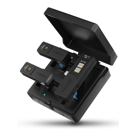
Lavalier Transmitter (TX) Handheld Transmitter (HTX) Receiver (RX)
Main Part:
Multiple Selections:
WM200 PRO (A) = 2TX + RX
WM200 PRO (C) = TX + RX
TX TX RX
++
TX RX
+
WM200 PRO-TX WM200 PRO-HTX
Packing List
3

①3.5mm TRS Lavalier Microphone
②3.5mm TRS-TRS Audio Cable
③3.5mm TRS-XLR Audio Cable
④Charging Cable
⑤Belt Clip
⑥Cold Shoe Mount
⑦Wind Mu
⑧Portable Box
⑨User Manual
⑩Warranty Card
Accessories:
The accessories of each combination include:
WM200 PRO (A) = ①x2 + ②+ ③+ ④+ ⑤x3 + ⑥+ ⑦+ ⑧+ ⑨+ ⑩
WM200 PRO (C) = ①+ ②+ ③+ ④+ ⑤x2 + ⑥+ ⑦+ ⑧+ ⑨+ ⑩
产品使用说明书
UHF全金属双通道无线麦克风
WM200 PRO-TX = ①+ ⑤ + ⑦+ ⑨+ ⑩
① ② ③ ④
⑤ ⑥ ⑦ ⑧
⑨ ⑩
4

Lavalier Transmitter (TX):
Components and Instruction
①IR Sensor
②MIC / Line in Audio Input Port
③Antenna
④Power / Muting Button
⑤LCD Screen
⑥Function Selection Button -
⑦Matching Status Indicator
⑧Audio Status Indicator
⑨SET Function Menu/ Recording Button
⑩Function Selection Button +
⑪TF Card Port
⑫Group Switch Button
⑬Belt Clip Port
⑭Battery Tray
⑮1/4 Threaded Hole
⑯USB-C Port
③
⑥
⑤
④
⑪
⑮
⑫
⑬
⑭
⑩
⑯
①
⑨
⑦ ⑧
②
5

Handheld Transmitter (HTX):
①Mic Capsule
②LCD Screen
③Power / Muting Button
④IR Sensor
⑤Low Cut Filter/Normal Audio Switch
⑥Signal Strength “High/Low” Switch
LCF
-
RF
High
Low
①
③
④
②
⑤ ⑥
6

Receiver (RX) :
①3.5mm Audio Output Port
②IR Sensor
③3.5mm Monitoring Port
④Group A Antenna
⑤Group A Working Status Indicator
⑥LCD Screen
⑦Function Selection Button -
⑧Power Button
⑨Group B Antenna
⑩Group B Working Status Indicator
⑪Function Selection Button +
⑫SET Function Menu Button
⑬Group Switch Button
⑭Belt Clip Port
⑮Battery Tray
⑯USB-C Port
④
⑥
⑦
⑤
⑩
⑨
⑪
⑬
⑭
⑮
⑯
① ③
②
⑧
⑫
7

Lavalier Transmitter (TX) :
Receiver (RX) :
A / RF:Group A Working Status Indicator
B / RF:Group B Working Status Indicator
Indicator Light Instruction
Blue Light Keeps on
Red Light Flickers
Channel matches (No matter the channel matched or not)
Muting mode
Low power reminder
Channel is matching (only for IR Sync)
RF
Blue Light Keeps on
Blue Light Flickers
Normal working status after the channel matched
Channel match failed
A / RF
B / RF
Blue Light Keeps on
Red Light Keeps on
Normal recording status
AUDIO
Red Light Flickers
Red Light Flickers Channel is matching (only for IR Sync)
Low power reminder
Red Light Keeps on Group closed
8

Lavalier Transmitter (TX)
Screen Display Instruction:
Screen Display and Operation Instruction
H
Group A
A
543.125MHzCH36
00:00:00
Signal Strength High
Signal Strength Low
Normal Recording
Muting
Recording
TF Card Inserted
TF Card Removed
Recording Time
Muting (Unlocking)
Muting (Locking)
Battery Power
Group A/B
Channel
Group A/B
Audio Dynamic Display Bar
Channel Frequency
H
L
REC
●
9

Operation Instruction:
1.Group A/B Selection
You could choose Group A or Group B based on your demand
2. Recording Function
At the home page and the screen lights up for long pressing button to record,
The of the screen flashes is recording;
At the home page and screen lights up for long pressing button to stop recording;
audio is stored in the TF card (Please purchase TF card by yourself)
Group A/B Switch Button
Recording ......
Recording Time
H
Group A
A
543.125MHzCH36
00:03:50
REC
●
"Update" or "Copy" function can not be used with Recording function at the
same time
10

H
CH Setting
A
CH36
H
CH Setting
A
3. Manually Adjust the Channel of Transmitter
3.1 Short press button to CH setting page
3.3 Short press button to the right channel
3.2 Long press button to enter the CH adjustment state
3.4 Short press button to confirm and other button of pages operate in the same
way
H
CH Setting
A
H
CH Setting
A
CH36
CH11
CH11
11

H
Input Setting
A
Line in
H
Input Setting
A
Mic
4. MIC/Line in Input Mode Adjustment
H
Low Cut Filter
A
Low
H
Low Cut Filter
A
High
H
Low Cut Filter
A
Off
5. Low Cut Filter ‘Low/High/OFF’ Adjustment
6. Transmitting Signal Strength Adjustment
H
FR Power
A
High
L
FR Power
A
Low
Mic mode is for Microphone input;
Line in mode is for external audio input, such as smartphone music player.
Selecting the corresponding input mode will bring you a better audio eect.
The LCF function will filter the low-frequency part of the audio source,
such as the sound of wild insects and the noise of the crowd, and the main audio
source will be thinner. When the LCF function is turned o, the original sound will
be restored, and the main sound source will be thicker. You can adjust to meet
your needs
With high signal strength, the wireless working distance is up to 80-120M, high
power consumption, standby time is short;
With low signal strength, the wireless working distance is up to 30-60M, low
power consumption, standby time is long
12

H
Muting
A
Enable
H
Muting
A
Disable
7. Muting Mode On/O
H
Backlight
A
60s
8. Time Adjustment for Backlight
H
Language(语言)
A
English
9. System Language
H
Clear TF Card
A
Yes
H
Clear TF Card
A
Left:046 H 24 M
H
Clear TF Card
A
No
10. Clear TF Card
Remaining Recording Time
When set to ‘ Disable ’, the muting function cannot be used, the icon is:
When set to ‘ Enable ’, the muting function works, the icon is:
The muting mode can be controlled only when the screen is on, press any
button to light the screen and then press the Power/Muting Button to switch the
muting mode.
13

TF Card Disk WM200_PRO
H
Update & Copy
A
On
H
Update & Copy
A
Off
11. Update & Copy
H
Reset
A
Yes
H
Reset
A
No
12. Reset
H
Version
A
X.X.X
13. Version
1. The recording function can only be used when the "update & copy" mode is o,
there are not a disk on the computer
2. When the "update & copy" mode is on, two disks appear after WM200 PRO is
connected with the computer, you can update firmware and copy audio file
3. Two disks appear after the WM200 PRO is connected to the computer, and
the recorded audio files can be copied from the disk of the TF card; Please copy
the upgrade file to WM200_ PRO disk, and then restart the WM200 PRO to upgrade
The name and memory of the TF card disk are determined by the TF card you purchased
14

Operation Instruction:
1.Turn on and Muting Mode Switch
1.1 Long press switch button for 2 seconds to turn on or o
1.2 when the screen is lighted on, short press the button to select muting mode
A
B
8 8
Normal Recording
A
B
8 8
Muting
The muting mode can be controlled only when the screen is lighted on, press
the button to light the screen and then press the button to switch the
muting mode
Handheld Transmitter (HTX)
Screen Display Instruction:
A
B
8 8
Normal Recording Muting Battery Power
Group A/B Channel
15

Group AGroup B
CH 36 CH 58
Group A Signal Strength
Group A Group B
Group A Channel Group B Channel
Group A transmitter Battery Group B transmitter Battery
Group A Audio Dynamic Bar Group B Audio Dynamic Bar
Group B Signal Strength Battery Power
A B
A B
Receiver (RX)
Screen Display Instruction:
Operation Instruction:
1. Group A/B/AB Selection
You could choose group A/B/AB based on your demand
Group A/B/AB Switch Button
Group A recording Group B recording
CH 36 CH 58
A B
A B
REC A REC B
16

Output Modle
Stereo
A B
A B
Output Modle
Stereo
A B
A B
Output Modle
Mono
A B
A B
Output Modle
Mono
A B
A B
2. Audio Output Mode ‘Stereo/Mono’ Adjustment
2.1 Short press button to ‘ Output Mode ’ page
2.2 Long press button to ‘ Output Mode ’ page
2.3 Short press button to select ‘ Mono/ Stereo ’ Output Mode
2.4 Short press button to confirm and other button of pages operate in the same way
When set to a single group A or group B, the output can only be mono mode
17

Setting
Group A
A B
A B
Group A Setting
CH46
A B
A B
Group A Setting
Auto scan? Yes
A B
A B
Group A Setting
Volume 12
A B
A B
Setting
Group B
A B
A B
4. Group A/B Channel Frequency Setting
5. Group A/B Volume Adjustment
6. Group A/B Automatic Channel Scan (Automatically scan the optimal frequency)
3. Group A/B Function Setting (Select the group you need to set)
18

Group A Setting
Sync? Yes
A B
A B
7. Sync
Backlight
30s
A B
A B
8. Time Adjustment for Backlight
Language(语言)
English
A B
A B
9. System Language
19
Other manuals for CVM-WM200
4
Table of contents
Other Comica Microphone manuals

Comica
Comica CVM-WS50H User manual

Comica
Comica STA-U2 User manual

Comica
Comica VM10 PRO User manual

Comica
Comica WM300 II User manual

Comica
Comica CVM-WM200 User manual

Comica
Comica CVM-VS50 User manual

Comica
Comica BoomX-U QUA User manual

Comica
Comica CVM-WM100 User manual

Comica
Comica CVM-WM100 User manual

Comica
Comica SIG.LAV V05 MI User manual

Comica
Comica CVM-WS60 COMBO User manual

Comica
Comica Vimo Q User manual

Comica
Comica BoomX-U User manual

Comica
Comica CVM-WM300 User manual

Comica
Comica CVM-VS07 User manual

Comica
Comica CVM-VS07 User manual

Comica
Comica Vimo C User manual

Comica
Comica CVM-WM100 User manual

Comica
Comica RGB Umic User manual

Comica
Comica VS09 MI User manual