Commodity Axis ViaAqua EF-3000 User manual

WARNING
Buyer/User assumes all responsability for safety and proper
use not in accordance with the directions and sately labels.

FEATURES
PRESSURE POND FILTER
• Easy to install and maintain
• Complete filtering system
• Terminator™ UVC Sterilizer (optional) for crystal clear water
• Multiple types of bio foam filtering media for beneficial aerobic bac-
teria
• Reverse flow filtration
• Backwash for cleaning
• Long lasting ceramic biological media
• Quad-action filtration for maximum efficiency
TERMINATOR™ UVC STERILIZER
• Safety switch built into UV cap
• Water resistant ballast
• E-39 connections
• PL compact UVC bulb
• Indicator light
The ViaAqua® Terminator™ UVC Sterilizer is equipped with a PL
UV bulb with a protected quartz sleeve that maintains the bulb
temperature, thus allowing 95% of the UV radiation to clarify the
water, helping to eliminate single celled free floating algae. Water
resistant ballast with E-39 wire connections and over 15 feet of wire
allows the ballast to be remotely mounted close to a GFCI electrical
outlet.
WARNING
»This product may contain chemicals known to the State of California to cause
cancer and/or birth defects or other reproductive harm. Wash you hand after
handling the product.
»It is your sole responsability to verify that the plug and receptacle are clean/
free of moisture and salt build up at all times. The receptacle must be free of
water, salt, calcium, and magnesium. Failure to do so may cause re and/or
loss of life.
»Do not plug into an extension cord or power strip.
»A drip loop must be used when plug into any electrical devices. A drip loop is
part of the cord hanging below the receptacle.
»The national code requires all aquarium equipment to be plugged into a G.F.C.I.
(Ground Fault Circuit Interrupter) electrical outlet. If you do not have a G.F.C.I.,
have an electrician install one prior to operating any aquarium components.

1
WARNING AND SAFEGUARD
• Readandfollowallinstructionsbeforeusingthe
ViaAqua®PressurePondFiltertoensureproper
useandapplication.
• Usethisproductforitsintendeduseonly.
• DonotoperatetheViaAqua®PressurePond
Filterwithoutwater.
• Youmustverifythatthereceptacleiscleanand
freeofwaterandmoisture.Failuretodosomay
causeelectricalarchingresultinginreorelectri-
calshock.
• Priortomaintenanceonanyelectricalappli-
anceorpond,youmustdisconnectallelectrical
aquariumdevices.
• Routinemaintenanceisrequiredtoensurethe
maximumperformanceandthelongevityofthe
ViaAqua®PressurePondFilter.(Seemainte-
nanceguidelines.)
• Neveryankorpullthecordfromtheelectricaloutlet.
• Donotoperateiftheplugorwireisdamaged.
• Verifythathandsaredrypriortodisconnectingthepower.
• Toreducetheriskofelectrocution,keepallconnectionsdry.
• DonotopenthePressurePondFilterwhenthepumpandlterare
operating.
• Donotuseanysoapsordetergentstocleananypartofthelter.
• Iftheproductfallsintothewaterdonotreachforit,unplugtheunitrst
thenretrievetheunitfromthewater.Ifanyoftheelectricalcomponents
getwetunplugimmediately.
WARNING FOR UNIT WITH TERMINATOR™
UVC STERILIZER
• TheUVlampproducesharmfulultravioletradiation.Donotlookdi-
rectlyattheUVCbulbwhenlit.Exposuretoultravioletlightcandam-
ageeyesandskin.
• DonotplugtheUVCsterilizerintoanextensioncord.
• Alwaysdisconnectthepowersupplybeforeopeningtheunitforser-
vice.FailuretodosowillexposetheusertoharmfulUVradiation.
• Althoughtheballastiswaterresistant,donotplacetheballastinan
areawhereitcancomeintocontactwithwater.
Drip
Loop
GFCI
ONLY

2
EF-4000 / EF-4000 UVC EF-4000 UVC
WATER CIRCULATION:
Regular Model (without UVC)
First,pre-lterthewater.Then,waterentersthebiologicalchamber
thathaslonglastingceramicmediadesignedtocreatehighamountsof
surfaceareaforbenecialbacteriatocultivateandbreakdownorganics.
Multipletypesofbiofoammechanicallyandbiologicallyaidinthe
removalandbiologicalbreakdownoforganics.Eachlevelofthebiofoam
ltrationfeaturesabuilt-inbypassroutethatwillredirectwaterifthebio
foambecomesclogged.
Model with Terminator™UVC Sterilizer
Designedformaximumefciency.WaterenterstheTerminator™UVC
Sterilizerforpermanentcontrolofsinglecelledalgae.Theefcient
reverseowquad-actionltrationsystemltersthewaterbiologically
andmechanically.Thewaterisrstpre-ltered.Then,waterentersthe
biologicalchamberthathaslonglastingceramicmediadesignedto
createhighamountsofsurfaceareaforbenecialbacteriatocultivate
andbreakdownorganics.Multipletypesofbiofoammechanicallyand
biologicallyaidintheremovalandbiologicalbreakdownoforganics.
Eachlevelofthebiofoamltrationfeaturesabuilt-inbypassroutethat
willredirectwaterifthebiofoambecomesclogged.
BACKWASH:
The integrated backwash system is built into the
top of the lter. The user friendly design makes
activation of the backwash as simple as turning
the dial. Once the dial is turned, the water ow
will reverse, removing the majority of built-up
sediment and debris. This feature can be used to
do water changes on ponds, making routine pond
maintenance simple and easy.

3
2
3
4
5
PART LIST:
1. Intake
2. Ouput
3. Backwash/sludge removal
4. Backwash knob
5. Terminator™ UVC Sterilizer (Optional.
See detail on page 11)
6. Barbed tting
7. Lid retainer clamp
8. Intake & Output tube
9. Fine bio foam
10. Medium bio foam
11. Coarse bio foam
12. Intake & output ares
13. Ceramic bio strainer lid
14. Ceramic bio chamber with media
15. Coarse prelter
16. Filter body
7
8
9
10
11
12
13
14
15
16
1
EF-3000
EF-3000 UVC
EF-4000
EF-4000 UVC
EF-5000
EF-5000 UVC
EF-6000
EF-6000 UVC
6

4
Sewage System
or Garden
Pond Pump
Pond Pump
Water Feature
Pond Pump
Point knob to
the intake port
1
2 3
4
5 6
Point knob
to the
backwash port
3 ft.
PRE-INSTALLATION SETUP
LOCATION FOR THE POND FILTER
• Place the pressure pond lter
level on a rm base.
• The location needs to be
free from ooding and well
ventilated.
• Protect the lter from direct
sunlight and moisture.
• Do not encapsulate lter.
• Place the lter a minimum of 3
ft. from the ponds edge.
• Verify that the location has
easy access to the lid for
removal during maintanance
and backwashing of the lter.
• Position the lter so that the
tubing will not kink.

5
Sewage System
or Garden
Pond Pump
Pond Pump
Water Feature
Pond Pump
Point knob to
the intake port
1
2 3
4
5 6
Point knob
to the
backwash port
CONNECTION
Requires either 1.25” ID or 1.5” ID tubing. It is important to choose the largest
diameter ID tubing possible. Tubing and hose clamps are not included.
1. Connect the barbed tting to the lter’s intake and output.
2. Contact Tubing to the Pressure Pond Filter:
• Inlet: Connect tubing from the ViaAqua®pond pump to the barbed
intake of the lter. Then secure with a hose clamp.
• Outlet: Connect tubing from the lter back to the pump or water
features. For maximum circulation, place the output and water
pump as far a part as possible. It is not recommended to place them
next to one another.
3. Turn the ow control knob pointing to the intake port.
4. Drain: Remove cap.
5. Connect barbed tting with a piece of tubing secure with a hose clamp.
6. To activate backwash turn off the pond pump and swith the ow control
knob so that the arrow points to the backwash/drain discharge port. Turn
the pond pump back on. Drain the water into a sewage system or garden.

6
Typical Operation
O-Ring
Point knob to
the output port
Point knob to
the backwash port
INSTALLATION SETUP
PRE-OPERATION PRECAUTION
• VerifythattheO-ringisproperlyinstalled.
• Doublecheckthatalltubingissecuredwitha
hoseclamp.Makesuretherearenokinksin
thetubing.
• IfusingaunitwithaUVCsterilizer,install
thePLcompactUVCbulbaccordingtothe
directions.
• Ensurethelidissecuredproperly.
• Ensuretheowcontrolknobarrowispointing
towardtheoutputport.
• Placethecapoftheackwash/drain
dischargeportbackon.
TYPICAL OPERATION
Forproperltration,operate
thepressurepondlter24
hoursaday,yearround.
1.StarttheViaAqua®pond
pump.
2.Verifythatallsealsand
connectionsarenotleaking.

7
Backwash Operation
O-Ring
Point knob to
the output port
Point knob to
the backwash port
3.UVCunit:
* PlugtheUVCsterilizerballastintoaGFCIoutletonly.
* BlueindicatorlightisonwhentheUVCunitisworking.
BACKWASH OPERATION
Backwashing lter should be performed at least once a week. A lter installed on an
exiting pond will require more frequent cleaning.
The lter needs to be cleaned when: - Dirty/cloudy water is in the lter.
- Reduced water ow.
1.Removethecapfromthebackwash/drainport.
2.Connectabarbedttingwithapieceoftubingandsecurewithahose
clamp.
3.Toactivatebackwash,turnoffthe
pondpumpandswitchtheowcontrol
knobsothatthearrowpointstothe
backwash/draindischargeport.
4.Turnthepondpumpbackon.
5.Drainthewaterintoa
sewagesystemorgarden.
Note: The cleaning system is using
pond water. Rell the pond with de-
chlorinated water.

8
ASSEMBLY OF THE MEDIA AND FILTER BODY
Follow these guidelines in order to reassemble the unit when the ltering
media and/or lid is removed for maintenance.
1.Insertthecoarseprelteratthe
bottomofthelterbody.
2.Verifythattheceramicbiochamber
lidislockedintoplacebyrotating
clockwisesothattheintakeand
outputholesarecompletelyopen
(seediagram2).
3.Usingthearrowontheceramic
chamberstrainerlid,alignthearrow
withtab/keyonthebrimofthelter
bodyandinserttheceramicbio
chamberintothegroovesofthe
lterbody.
4.Alllteringfoamandintake/output
aresmustbeinstalledproperlyas
indicatedinthepartlistonpage#3.
5.VerifytheO-ringisproperlyinstalled
andclean.
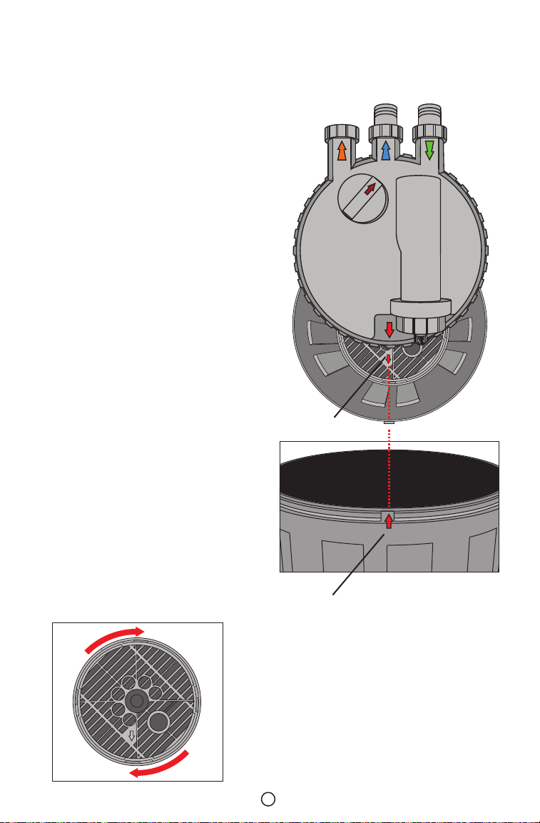
6.Alignthearrowonthelterlidwith
thetab/keyonthebrimofthelter
body(seediagram1).
7.Nowwithoutanyangles,insertthe
intake/outputaresdirectlyinto
intake/outputholesintheceramic
biochamber.
8.Installthelidretainerclapverifying
thatthethreenotchesonthetopof
theclamparefacingup.Alignthe
notcheswiththedischargeports.
9.Securetheclasp.
Diagram 1: To reassembly the unit back,
the arrow on the filter lid must align with
the tab/key on the brim of the filter body.
Tab/key on the filter body
Strainer lid arrow
Diagram 2: Turn clockwise the
strainer lid to secure the ceramic
bio chamber.

9
SPECIFICATIONS OF THE PRESSURE POND FILTER
Model Recommended
PumpSize
UVC
watt
IDPipe
Size
Required
Filtering
Capacity
Filter
Height
UPC#
0069037
EF-3000
700-1300GPH
-
1.25in
or
1.5in
15.5L 14.25in.
29529
EF-3000UVC 529536
EF-4000
1300-2100GPH
-
21.5L 18.25in.
29543
EF-4000UVC 929550
EF-5000
1300-3000GPH
-
27.5L 22.25in.
29567
EF-5000UVC 929574
EF-6000
1300-4000GPH
-
33.5L 26.25in.
29581
EF-6000UVC 929598
SELECTION OF VIAAQUA®POND PUMP
Model Qmax
Liters per Hour
Qmax
Gallon per hour
Hmax
meter Watts Max.
Head
Voltage/
Frequency
UPC #
0069037
DP-5000 5000 LPH 1320 GPH 2 M 55 W 5.2 FT.
110-120V/
60 Hz
TBA
DP-7000 6500 LPH 1716 GPH 2.5 M 70 W 6.56 FT. TBA
DP-9000 7500 LPH 1980 GPH 3 M 80 W 8.85 FT. TBA
DP-12000 10500 LPH 2772 GPH 5 M 130 W 13.12 FT. TBA
DP-15000 12500 LPH 3300 GPH 5.5 M 180 W 14.76 FT. TBA
DP-18000 14500 LPH 3828 GPH 6.5 M 250 W 16.4 FT. 2966 6
DP-20000 16500 LPH 4356 GPH 7 M 350 W 23 FT. TBA
IMPORTANT:
Donotoperatethelterwithapumphavingwaterpressuregreaterthan5PSI.
Donotoperatethelterwithapoolorajacuzzipump.Whenselectingapond
pump,keepinmindthattheheadpressurewilldecreasewaterow.There
areotherViaAqua®pondpumpsavailablethatwilltyourspecicapplication.
Consultyourlocaldealerforthebestpumpforyourgivenapplication.

10
MAINTENANCE
FILTER
Whenbackwashing,ifthelterdoesnotproduceexpectedresults,itis
necessarytocleanorreplacefoammedia.Thisshouldbeperformedat
leastonceaseason.However,thisisnotaruleforpondandoutdoor
environmentsvarythusmorefrequentcleaningmayberequired.
• UnplugtheTerminator™UVCSterilizer.
• Turnthepondpumpoff.
• Disconnectthebarbedttingfromthelter.
• Flipoutsafetylockandremovelidretainerclamp.
• Removethelidofthelter.Handlewithcare.TheUVCbulbandquartz
sleeveismadeofglass.
• Removetheintakeandoutputares.(SeePartListonpage3).
• Removeandrinsefoampads.Replacethemifnecessary.
• Removethebio-chamberandrinsewellwithpondwateronly.
Biologicalmediabenecialbacteriawillbekillediftapwaterisusedto
rinse.
• Removeandrinsepre-lterfoampads.Replacethemifnecessary.
• Rinseandcleanthelterbody.
• Placethelteringmediabackintheiroriginallocations.Replaceintake
andoutputares.
• Replaceo-ringandverifythatitisclean.Werecommendusingasmall
amountofsiliconelubricantontheo-ringtoensureaproperseal.
• Securelidwithlidretainerclamp.Thelidretainerclampmustbe
alignedsothatthenotchesinthetopoftheclamptundertheintake
anddischargeport.
• Filterisreadytouse.Seeinstallationinstructions.
UVC BULB
• Followallthesafeguardsandwarningsofthemanufacture.
• BeforedoinganymaintenanceontheUVCsterilizer,thepowersupply
andwatersupplymustbedisconnected.
• Onlyinraresituationsdoesthequartzsleeveeverhavetobe
removed.Ifnecessaryloosenscrewscarefully,thenremovethequartz
sleeve.Ifexcessforceisusedthequartzsleevewillbreak.After
removed,useasoftcleanclothtogentlyremoveanyexcessgrim
and/ordebris.Reassembleusingasmallamountofsiliconelubricant
placedontheo-ringpriortoslidingitintothemainbodyoftheUVC
sterilizer.

11
• TheUVCbulbneedstobereplacedevery8,000to9,000hours.This
willensureoptimumperformance.
• TheefciencyoftheTerminator™UVCSterilizerdependsonthe
durationtheUVlightisincontactwithwater.Thustherateofwater
ow,notthewaythewatertravels,willrelatetotheefciencyofthe
UVCsterilizer.
UVC BULB REPLACEMENT
• UnscrewthethreadedUVCbulbcapontheendoftheUVCsterilizer.
Onceunscrewed,theinsideofthecapwillrevealtheUVCbulbsocket.
• RemovetheUVCbulbfromthebox.Important:Donottouchthequartz
areaofthebulb.Ifneededuseacleanclothtohandlethebulb.
• Alignthepinswiththeholesinthebulbsocket.Pressthebulbdirectly
intotheholesinthebulbsocket.Avoidallangles,failuretodosomay
causepermanentdamagetothebulband/orthebulbsocket.
• ScrewcapbackontotheUVCsterilizer.
Lid and Bulb Socket UVC PL Bulb Reaction Chamber
17 18 19 20
Quartz Sleeve

12
REPLACEMENT PART
Part
Number Description ForPondFilterModel UPC#
0069037
9Finebiofoam(2in.)2/bag
EF-3000/EF-3000UVC
EF-4000/EF-4000UVC
EF-5000/EF-5000UVC
EF-6000/EF-6000UVC
29758
10 Mediumbiofoam(1.5in.)2/bag EF-4000/EF-4000UVC
EF-5000/EF-5000UVC
EF-6000/EF-6000UVC
29765
10 Mediumbiofoam(2.25in.)2/bag 29772
11 Coarsebiofoam(2.75in.)2/bag
EF-3000/EF-3000UVC
EF-4000/EF-4000UVC
EF-5000/EF-5000UVC
EF-6000/EF-6000UVC
29789
15 Coarseprelter(2.75in.)2/bag
EF-3000/EF-3000UVC
EF-4000/EF-4000UVC
EF-5000/EF-5000UVC
29796
15 Coarseprelter(4in.)2/bag EF-6000/EF-6000UVC 29802
18 UVCbulb5watt EF-3000UVC 20663
18 UVCbulb9watt
EF-4000UVC
EF-5000UVC
EF-6000UVC
23671
LIMITED WARRANTY
CommodityAxisInc.warrantsthattheViaAqua®PondFilterisfreefromdefects
foraperiodofoneyearfromtheinitialdateofpurchaseshownwiththeoriginal
cash register receipt. Commodity Axis Inc. disclaims all other warranties of
merchantability and/or fitness for a particular purpose. Although this limited
warrantymaygiveyouspecificrights,youmayhaveotherrightsthatmayvary
fromstatetostate.ThiswarrantyisvoidifthefailureoftheViaAqua®PondFilter
or any part, sealant or component there of is due to (i) misuse, (ii) tampering,
(iii)negligence,(iv) misapplication, (v)abuse,(vi) accident and/or(vii)failureto
properly (a) maintain, (b) clean, (c) keep in contact with water and or use the
ViaAqua®PondFilterwithaGroundFaultCircuitInterrupter(G.F.C.I.).
CONSUMER REMEDIES
CommodityAxisInc.entireliabilityandyoursoleexclusiveremedybe,eitherthe
repairorreplacementoftheViaAqua®PondFilteronlyifthereturnthedefective
ViaAqua®PondFilterdirectlytoCommodityAxisInc.withtheoriginalcashregister
receipt in this original box along with $25.00 for shipping and handling. Do not
sendtheViaAqua®PondFilterbyinsuredmail.TheViaAqua®PondFiltermaybe
sentbyUPSrequiringasignatureonarrival.AnyreplacementofViaAqua®Pond
Filter will be warranted for the remaining for the original warranty period. In no
eventwillshippingchargesbereimbursed.InnoteventwillCommodityAxisInc.
beliableforanyconsequentialorincidentaldamagesincluding,butnotlimitedto
lossoflife,personalinjury,propertydamage,damagedequipment,lostprofits,lost
wages,lostsavings,lostincome,etc.Somestatesdonotallowforthelimitations
or exclusion of liability for incidental or consequential damages, so the above
exclusionmaynotapplytoyou.

Name Date
Address
City State Zip Code
Country Home Phone
Cell Phone Email
Date of Purchase Seller (Retail Name)
Seller’s Location Phone
*Afx a copy of your original purchase receipt here.Please mail warranty card and proof of
purchase within 15 days of purchase to:
Commodity Axis® Inc., 300 South Lewis Rd. Unit J. Camarillo CA 93012
IMPORTANT: Please make a copy of this warranty card and retain it for your records. Warranty
policy is subject to change without notice.
REGISTRATION CARD
ONE (1) YEAR WARRANTY
Bringing Products to Life
300 South Lewis Rd. Unit J. Camarillo CA 93012
Fax: (888) 989 0878
www.ViaAquaOceanpure.com
This manual suits for next models
7
Table of contents
Other Commodity Axis Water Filtration System manuals
Popular Water Filtration System manuals by other brands

Master Water Conditioning
Master Water Conditioning MBA Series Installation and operation manual

Bühler technologies
Bühler technologies AGF-FE-1 Installation and operation instructions

Oase
Oase Filtoclear 3000 operating instructions

Lancaster
Lancaster XFACTOR 7-LX125F-DAN-1B Installation, operating and service manual

IDEAL H2O
IDEAL H2O 100 GPD Setup and maintenance guide

GE
GE GXSV65F Owner's manual and installation instructions