Compass HD Owner’s Manual – Models GP620 SS, GP620 CC Revised 10/27/14
9
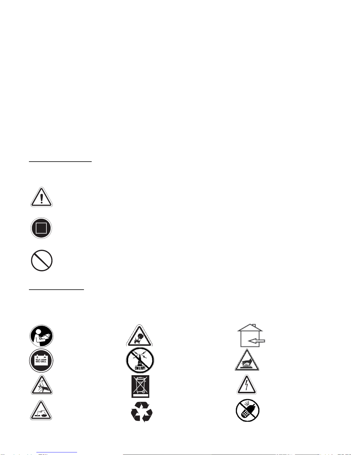
EMI/RFI
The rapid development of electronics, especially in the area of communications, has
saturated our environment with electromagnetic (radio) waves that are emitted by
television transmitters, cellular phones, citizen’s band radios (CBs), amateur radios
(ham radios), wireless computer links, microwave transmitters, paging transmitters,
etc. These electromagnetic (EM) waves are invisible and increase in strength the closer
one gets to the source of transmission. When these energy waves act upon electrical
devices and cause them to malfunction or to function in an erratic or uncontrolled
manner, they are referred to as Electromagnetic Interference (EMI) or Radio Frequency
Interference (RFI).
EMI/RFI AND YOUR Compass HD™
All electrically powered vehicles, including power chairs are susceptible to EMI/RFI.
This interference could result in abnormal, unintended movement of a power
wheelchair.
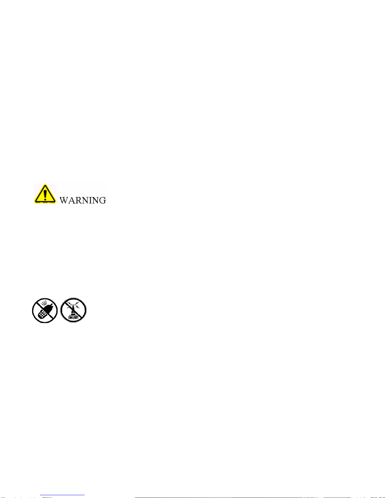
Unintended movement or brake release could cause an accident
or injury.
The FDA has determined that each make and model of power chair can resist EMI/RFI
to a certain level. The higher the level of immunity, the greater the degree of protection
from EMI/RFI measured in volts per meter (V/m). The FDA has also determined that
current technology is capable of providing 20 V/m of immunity to EMI/RFI, which
would provide useful protection against common sources of interference. This product
has been tested and has passed an immunity level of 20 V/m.
EMI/RFI RECOMMENDATIONS
PROHIBITED! Do not turn on or use hand-held personal electronic
communication devices such as cellular phones, walkie-talkies, and CB
radios while your power chair is turned on.
Be aware of any nearby transmitters (radio, television, microwave, etc.) on your
intended route and avoid operating your chair close to any of those transmitters.
Turn off the power if your Compass HD™is going to be in a stationary position for
any length of time.
Be aware that adding accessories or components or modifying your power chair may
make it more susceptible to EMI/RFI.
If unintended movement or brake release occurs, turn your power chair off as soon
as it is safe to do so.
Turn off your power chair as soon as it is safely possible if
unintended or uncontrollable motion occurs or if unintended brake release
occurs.