Tuffcare Rhino P440 User manual


23
RHINO STAND UP PATIENT LIFTER P440 and P445 RHINO STAND UP PATIENT LIFTER P440 and P445
TABLE OF CONTENTS
3
4
6
9
10
11
11
12
13
14
15
16
17
17
17
18
20
21
23
26
28
30
30
30
30
31
Product Specifications
Product Diagram
General Guidelines
SECTION 1 - General Guidelines
SECTION 2 - Assembly
Assembling the Mast Assembly to the Base
Assembling the Foot Step to the Mast
Assembling the Knee Pad to the Mast
Attach the Hi-Low Actuator to the Mast Assembly
Attaching the Control Unit on Mounting Bracket
Attaching the Battery Case on Control Unit
Prepare the Patient Lifter for Use
Locking/Unlocking the Rear Casters
Raising/Lowering the Patient Lifter
Closing/Opening the Legs
Using the Emergency Stop
Activating a Mechanical Emergency Release
Charging the Battery
Positioning the Stand up Lifter
Lifting the Patient
Moving the Patient
Transferring to a Wheelchair
Transferring to a Bed
Maintenance Safety Inspection Checklist
Cleaning the Lifter
Detecting Wear and Damage
Lubricating the Lifter
Warranty
SECTION 3 - Operation
SECTION 4 - Lifting the Patient
SECTION 5 - Transferring the Patient
SECTION 6 - Maintenance
SECTION 7 - Limited Warranty
Height at Sling Hook-up - MAX.: 70 inches
Height at Sling Hook-up - MIN.: 37 inches
Base Width OPEN: 32 inches
Base Width CLOSED: 21 inches
Base Height (Clearance): 4.5 inches
Base Length: 42 inches
Overall Height: 70 inches
Overall Length: 42 inches
Overall Width: 25.5 inches
Casters: 3” Dual Front and 4” Rear with Brake
Sling Options: Standing or Transfer
Sling Material: Polyester
Weight Capacity: 350 lbs
Weight without sling: P440 - 109 lbs, P445 – 121 lbs
Battery: 24V DC (RCHBL)
Charger Input: 100-240V AC
Charger Output/Charging Time: 29.5V DC Max 6 hours
Motor Safety Devices: Anti-Entrapment
Emergency Stop Button: Yes
Limited Warranty Lifter/Electronics: 3 Years/1 Year
PRODUCT SPECIFICATION
P440/445 RHINO STAND UP PATIENT LIFTER

45
RHINO STAND UP PATIENT LIFTER P440 and P445 RHINO STAND UP PATIENT LIFTER P440 and P445
PRODUCT DIAGRAM
Hand Pendant
Attachment (Sling)Holders
Lift Arm
Mast
Hi-low Actuator
Knee Pad
Adjusting Legs
A
B
C
D
E
F
G
H
I
J
K
L
M
N
Dual Front Caster Wheels without Brake
Footplate
Rear Caster Wheel with Brake
Foot Pedal (For P440)
Control Unit
Battery Case
Handle Bar
C
B
D
E
Manufacturer Tag
Model Number
Serial Number
Country of Origin
A
F
G
H
I
WARNING: Danger
( See next page)
K
L
M
N
J
DANGER! RISK OF ELECTRICAL AND FIRE HAZARD. MAY
RESULT IN DEATH, SERIOUS INJURY, SHOCK OR BURNS.
This charger, like all electrical products. MUST be treated with
respect. Follow these instructions to reduce electrical hazard risk.
TO HELP REDUCE THIS RISK:
PROPER GROUNDING OF AC POWER CORD
Charger MUST be grounded to reduce risk of electric shock
Charger is equipped with an electric cord having an equipment
grounding conductor and a grounding plug. The plug MUST be
plugged into an outlet that Is properly Installed and grounded
in accordance with all local codes and ordinances. If you ever
feel even a slight shock from this or any electrical appliance, or
equipment connected to it, such as your chair or carrier STOP. Turn
off electricity to outlet, and have it inspected by an electrician. You
may have a dangerous, improperly wired outlet.
DANGER - NEVER alter AC power cord or plug provided. If
it will not fit outlet, have proper outlet installed by a qualified
electrician. Improper connection can result in a risk of an electric
shock. This battery charger is for use ona nominal 120 volt circuit
(common household current), and has a grounding plug. A
temporary adapter may be used to connect this plug to a two-
pole receptacle if properly grounded outlet is not available. The
temporary adapter should be used only until a qualified electrician
can install a properly grounded outlet.
Instruction for Adjusting
Legs (for P440 Only)
ADJUSTING LEGS
(FOR P440 ONLY)
LEGS SECTION MOTOR
(FOR P445)
P440 – SEMI HI-LOW / P445 – FULL HI-LOW WITH LEG

67
RHINO STAND UP PATIENT LIFTER P440 and P445 RHINO STAND UP PATIENT LIFTER P440 and P445
WEIGHT LIMIT
DO NOT exceed maximum weight limit of the patient lifter.
The weight limit for the stand up lifter is 350 lbs.
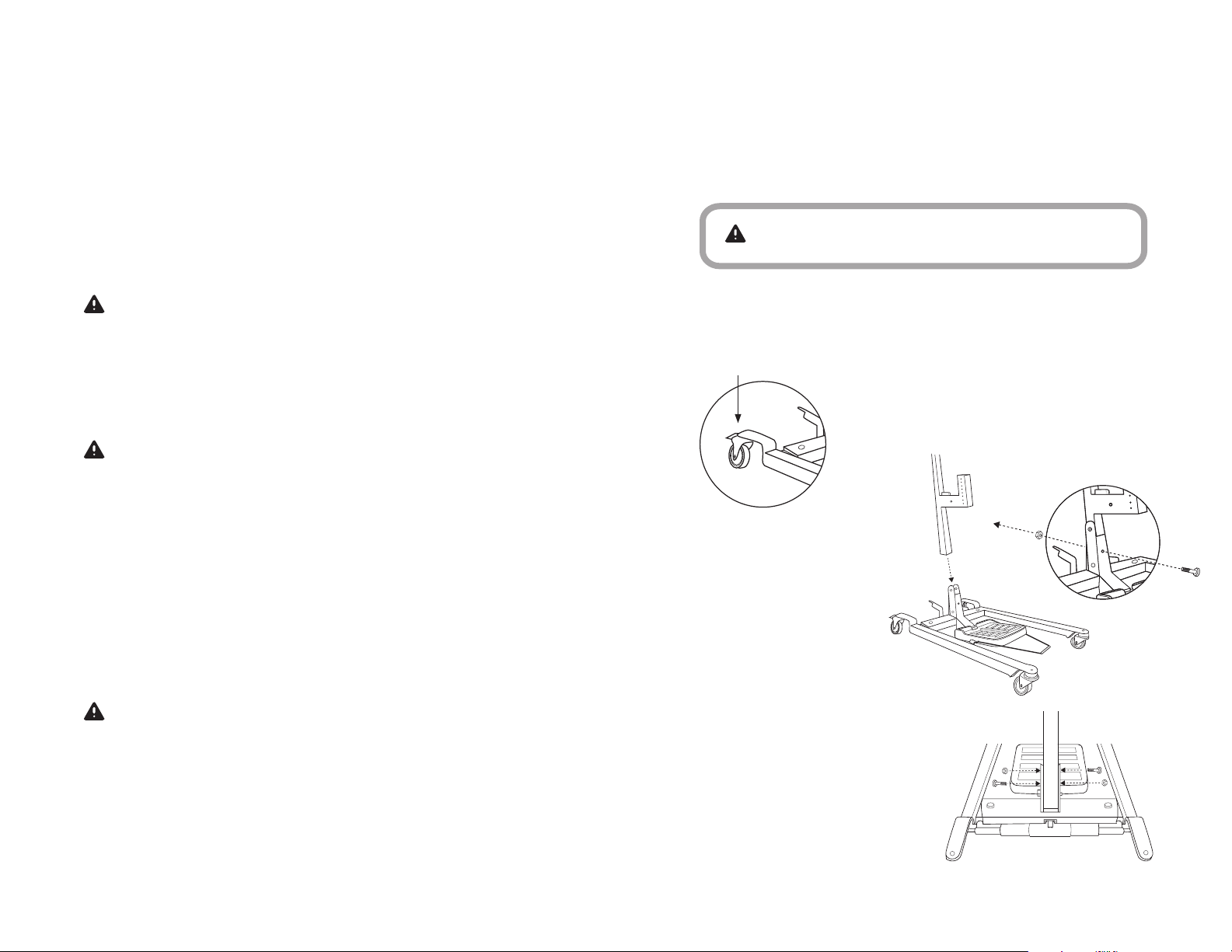
ASSEMBLING THE LIFTER
DO NOT over-tightens mounting hardware. It will cause a
damage of mounting brackets.
USING THE SLING
Be sure that sling is properly attached on sling holders before
the patient is removed from a bed, chair or any objects.
If the patient is in a wheelchair, secure the wheel locks in place
to prevent the chair from moving forwards or backwards.
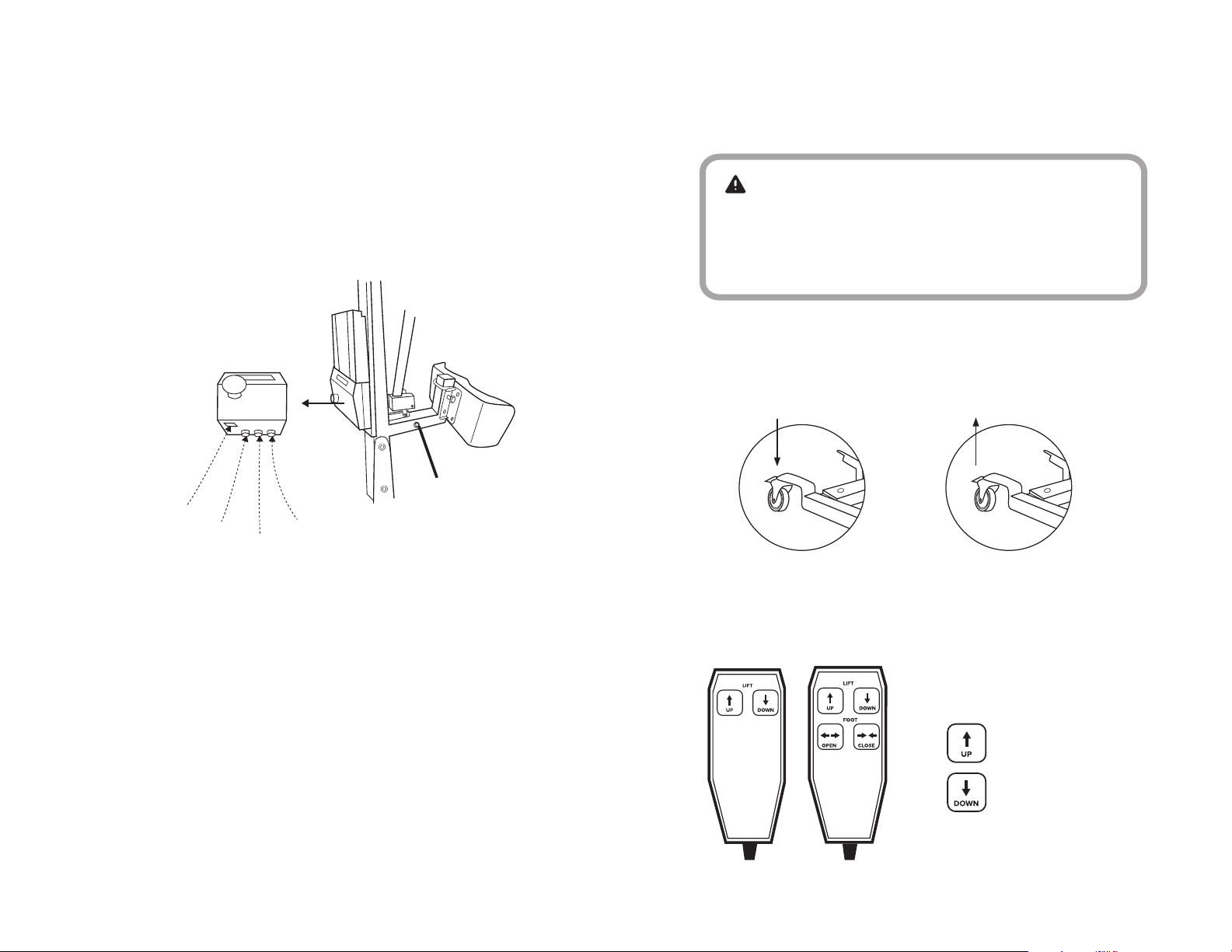
OPERATING THE LIFTER
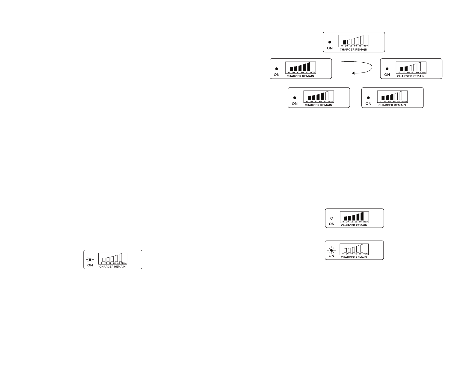
Prior to first, make sure that battery is being fully charged.
Always use the handles to move the lifter.
LIFTING THE PATIENT
Before positioning the legs of the stand-up lifter around the
patient, make sure that the patient’s feet are out of the way of
the foot plate, otherwise injury may occur.
Adjustments for safety and comfort should be made before
moving the patient. Patient’s arms should be outside of the
sling straps.
Before lifting a patient from a wheelchair, bed or any objects,
slightly raise the patient off the object and check that sling
attachments are secured.
During transfer, with the patient suspended in a sling attached
to the lifter, DO NOT roll caster base over uneven surfaces that
would create an imbalance of the patient lifter and could
cause the patient lifter to tip over. Uses handle on the mast at
all times to move the patient lifter.
GENERAL GUIDELINES contains important information for the
safe operation and use of this Medical Device.
SECTION 1
GENERAL GUIDELINES
Check all parts for shipping damage before using. In
case of damage, DO NOT use the equipment.
The TUFFCARE patient lifter is NOT a transport
device. It is intended to transfer a patient from
one seated surface to another (such as a bed to a
wheelchair).
DO NOT attempt to transfer, the user must be
assessed by a qualified professional. Thoroughly
read and fully understand the instructions in this
Owner’s Manual,
TUFFCARE Stand up and Transfer slings are
specifically designed to be used in conjunction with
TUFFCARE patient lifter. Slings and accessories
designed by other manufacturers are not to be
utilized as a component of Tuffcare’s patient lifter
system.
The stand up lifter is intended to be used for patient
within weight limit indicated for the lifter. DO
NOT attempt to lifter more than the weight limit
indicated.
1
2
3
4
5
WARNING

89
RHINO STAND UP PATIENT LIFTER P440 and P445 RHINO STAND UP PATIENT LIFTER P440 and P445
ASSEMBLING THE MAST ASSEMBLY
TO THE BASE
TUFFCARE suggests locking the rear casters ONLY when
positioning or removing the sling (stand up or transfer) from
around the patient.
TUFFCARE DOES NOT suggests locking the rear casters
of the patient lifter when lifting a patient. Doing so could
cause the
lifter to tip over and endanger the patient and assistants.
TRANSFERRING THE PATIENT
Before transferring, check that the lifter’s weight capacity
can withstand the patient’s weight.
Wheelchair wheel locks MUST be in a locked position before
lowering the patient into the wheelchair for transport.
PERFORMING MAINTENANCE
Regular maintenance of patient lifter and accessories is
required to assure proper operation.
Casters and axle bolts are also required to be checked for
tightness.
DO NOT over-tightens mounting hardware. It will cause a
damage of mounting brackets.
NOTE: See detail at Section 6 for maintenance.
PINCH POINTS
Pinch points exist at base of lifter. Use caution, otherwise
injury could occur.
SECTION 2
ASSEMBLY
Pre-assembled one piece grid design frame with fully loaded
electronics system, not assembling requires for main frame.
1 Set base on the floor. Lock both rear casters
before lifting up the mast.
WARNING
Use only Tuffcare parts to complete this stand up patient lifter.
Use the included ranch to
secure the bolts and nuts.
Note: two longer bolts use on
side by side (upper & lower
holes), short one uses on the
middle.
Check and tighten all hardware
BEFORE use.
2 Position the mast to mounting
bracket on the base.
STEP DOWN TO LOCK
3
4

10 11
RHINO STAND UP PATIENT LIFTER P440 and P445 RHINO STAND UP PATIENT LIFTER P440 and P445
ASSEMBLING THE FOOT STEP
TO THE MAST
ATTACH THE HI-LOW ACTUATOR TO THE
MAST ASSEMBLY
ADJUSTING THE HEIGHT OF KNEE PAD
Set foot step on the floor. Lifting up connecting cables.
Use pin and lock to secure the cables on the bracket on
the mast.
Check and tighten all hardware BEFORE use.
Use both hands, pull both adjustment pins outward
at the same time.
Position the knee pad to the desired height on the mast and
release adjustment pins into the alignment holes.
Check to make sure that both pins are completed engaged.
Install the pin through the
holes of the hi-low actuator
and mast bracket and
secure with hitch pin.
1
2
3
PULL OUTWARDS
PULL OUTWARDS
1
2
3
1Position the hi-low actuator
between the mast bracket.
2

12 13
RHINO STAND UP PATIENT LIFTER P440 and P445 RHINO STAND UP PATIENT LIFTER P440 and P445
Move the lift arm to align
the holes in the hi-low
actuator with the holes in
the arm bracket.
Install the pin through the
holes of the hi-low actuator
and arm bracket and
secure with hitch pin.
Lift up on the handle on the back of
battery case.
Place the battery case on control unit
at the desired position.
Push the top of battery case against
mounting bracket until there is an
audible click
PUSH
HANDLE
Place the control unit on
the mounting bracket at
the desired position.
Screw the mounting screws
through the control unit into
mounting bracket. Tighten
securely.
3
4
1
2
3
1
2
ATTACHING THE CONTROL UNIT ON
MOUNTING BRACKET
ATTACHING THE BATTERY CASE
ON CONTROL UNIT
WARNING
Make sure there is an audible click when plugging battery
case on control unit. Otherwise, injury or damage may occur.

14 15
RHINO STAND UP PATIENT LIFTER P440 and P445 RHINO STAND UP PATIENT LIFTER P440 and P445
PREPARE THE PATIENT LIFT FOR USE
LOCKING/UNLOCKING THE
REAR CASTERS
RAISING/LOWERING THE
PATIENT LIFT
Plug the hand control, leg actuator (For P445 Full Electronic
Stand-up Lifter Only) and hi-low actuator into the connections
on the bottom of the control unit.
Check and tighten all hardware BEFORE use.
Control Unit
Plug for Power Cord
Plug for Hi-low Actuator
Plug for Pendant
Plug for Leg Actuator
For P445 only
1
2
SECTION 3
OPERATION
WARNING
DO NOT attempt to transfer, the user must be
assessed by a qualified professional. Thoroughly
read and fully understand the instructions in this
Owner’s Manual.
LOCK
P440 P445
UNLOCK
PRESS To Raise the
Patient Lift
PRESS To Lower the
Patient Lift
Controls the
Hi-low section

16 17
RHINO STAND UP PATIENT LIFTER P440 and P445 RHINO STAND UP PATIENT LIFTER P440 and P445
CLOSING/OPENING THE LEGS
To Open and Close the Legs on P445
Press the open and close button on
the hand control.
To Open and Close the Legs on P440
Step down on left side of “Leg Adjusting Stepper” to
close the legs
Step down on right side of “Leg Adjusting Stepper” to
open the leg.
Leg Adjusting Stepper for P440
To reset, rotate the emergency
button clockwise.
EMERGENCY RELEASE
To activate the emergency release, push the
Red Button (powered by 9V battery) located on
the side of Hi-low actuator to lowering down
the lift arm.
Open the battery cover located at the
base of liner hi-low actuator. Insert a 9
Volt battery into and replace cover.
Note: The battery is provided the power
for emergency lowering down.
RED emergency
button on Control Unit
Red button out = Powered On
Red button pushed in = Power Off
USING THE EMERGENCY STOP
ACTIVATING A MECHANICAL
EMERGENCY RELEASE
REPLACE EMERGENCY
RELEASE BATTERY
Push the RED emergency button
in to stop the lift arms
from raising or lowering.

18 19
RHINO STAND UP PATIENT LIFTER P440 and P445 RHINO STAND UP PATIENT LIFTER P440 and P445
When the battery reserve reaches a desirable level the battery
meter stops flashing and the LED turns from red to green.
Now the battery meter will indicate a full gauge when all the
bars light up. At this time the charger utilizes a slow charging
“Absorption Charge”, leave charging for 4 to 6 hours.
When the battery becomes fully charged, the battery meter
indicator bars turn off. Unplug the charging cord and the lifter
will be ready for use.
CHARGING THE BATTERY
NOTE:
I
t is suggested to recharge the battery daily to prolong
its life cycle.
1.
Place the battery on the control unit to charge battery.
Push the top of the battery against the mounting bracket until
there is an audible click, See more details on pages (15-16)
for Attaching the Battery Pack onto the Control Unit.
2.
Make sure the red emergency button is fully pulled out and
at the on position. (When emergency button is pressed down,
the circuit is off and the unit will not function or charge.
3. Plug the power code into a 110 Volt outlet.
NOTE:
When plugged into an AC outlet the safe protect feature
turns on, disabling the control pendent from functioning. The
unit will not function while plugged in.
NOTE:
The charge LED will light up red while charging. When
fully charged, the LED will stop illuminating.
NOTE:
It will take approximately (4) hours to charge a battery
that requires a full charge.
When the charging power cord is plugged into an electrical
outlet, the red LED light on the left of the battery will come on.
When the built-in charging system senses a drop in battery
voltage,then the charging system automatically increases its
output to re-charge the battery.
The bars on the battery meter will begin to flash based on the
remaining percentage of the charge, the flashing bar slowly
increases when the battery is taking charge. This indicates
that the battery is charging on a fast mode “Bulk Charge”.
Fast charging usually last for 30 min.
NOTE:
If the charging cord is plugged in and the battery
meter does not indicate this it suggests the circuit is off, the
battery is fully charged, or a faulty battery(Have the battery
pack replaced).

20 21
RHINO STAND UP PATIENT LIFTER P440 and P445 RHINO STAND UP PATIENT LIFTER P440 and P445
SECTION 4
LIFTING THE PATIENT
WARNING
DO NOT exceed the maximum weight limit of
350 lbs.
DO NOT attempt to transfer, the user must be
assessed by a qualified professional. Thoroughly
read and fully understand the instructions in this
Owner’s Manual.
ALWAYS keep hands and fingers clear of moving
parts to avoid injury.
Individuals that use the stand-up patient sling MUST
be able to support their own weight, otherwise
injury may occur.
DO NOT move the patient if the patient sling is not
properly connected to the attachment holders on
the lift arm. Check that the patient sling is properly
connected to the attachment holders BEFORE
lifting the patient.
During transfer, with the patient suspended in the
patient sling, DO NOT roll the base of the patient
lifter over any uneven surfaces that would cause the
patient lifter to become unstable.
ALWAYS use the handle on the mast assembly to
move the stand up lifter to ensure the safety.
1
2
3
4
5
6
WARNING
The legs of the stand-up lifter MUST be in the
maximum open position for stability and safety.
POSITIONING THE STAND UP LIFTER
Press the “FOOT” – “OPEN”
button on the hand control to
open the legs to the maximum
open position.
1 Obtain stability.
Step down on right side of “Leg Adjusting Stepper” to open the
legs to the maximum open position.
P445
P440
Step down on right to OPEN
Maximum Open
Position is 30”

22 23
RHINO STAND UP PATIENT LIFTER P440 and P445 RHINO STAND UP PATIENT LIFTER P440 and P445
2 Position the stand up lifter using the handle on the mast.
3 Press the “ LIFT” – “DOWN” button on the hand control to lower
the lift arms for easy attachment to the sling.
Handle
P445
Lower Arms for Attachment
Lift arms
LIFTING THE PATIENT
WARNING
DO NOT exceed the maximum weight limit
of 350 lbs.
DO NOT attempt to transfer, the user must be
assessed by a qualified professional. Thoroughly
read and fully understand the instructions in this
Owner’s Manual.
ALWAYS keep hands and fingers clear of moving
parts to avoid injury.
Individuals that use the stand-up patient sling MUST
be able to support their own weight, otherwise
injury may occur.
DO NOT move the patient if the patient sling is not
properly connected to the attachment holders on
the lift arm. Check that the patient sling is properly
connected to the attachment holders BEFORE
lifting the patient.
During transfer, with the patient suspended in the
patient sling, DO NOT roll the base of the patient
lifter over any uneven surfaces that would cause the
patient lifter to become unstable.
ALWAYS use the handle on the mast assembly to
move the stand up lifter to ensure the safety.

24 25
RHINO STAND UP PATIENT LIFTER P440 and P445 RHINO STAND UP PATIENT LIFTER P440 and P445
NOTE: The patient MUST be in a seated position first. Use the
head section of the bed to get the patient upright then move
legs over the side of the bed.
ENSURE THE FOLLOWING:
1The patient’s knees are secure against the knee pad.
2The patient’s feet are properly positioned on the foot plate.
3Slings:
AStanding Sling - the bottom edge of the standing sling is
positioned on the patient’s lower back.
BTransfer Sling - the bottom edge of the transfer sling is at the
base of the patient’s spine.
4The rear casters are unlocked.
5 The legs are in the maximum open position.
Instruct the patient to hold onto
the lift arms on both sides of the
stand up lifter.
Instruct the patient to lean back
into the standing or transfer
sling.
WARNING
Standing Slings - Before lifting the patient, make
sure the bottom edge of the standing sling is
positioned on the lower back of the patient and the
patient’s arms are outside the sling.
Transfer Slings - Before lifting the patient, make
sure the bottom edge of the transfer sling is at the
base of the attachment holders and the patient’s
arms are outside the sling.
Lower Arms for Attachment
Lift arms
1
2

26 27
RHINO STAND UP PATIENT LIFTER P440 and P445 RHINO STAND UP PATIENT LIFTER P440 and P445
SECTION 5
TRANSFERRING THE
PATIENT
DO NOT attempt to transfer, the user must be
assessed by a qualified professional. Thoroughly
read and fully understand the instructions in this
Owner’s Manual.
DO NOT move the patient if the sling is not properly
connected to the attachment holders of the stand
up lifter. Check that the sling is properly connected
to the attachment holders prior to lifting a patient.
DO NOT use slings and stand up lifter of different
manufacturers. TUFFCARE slings are made
specifically for use with TUFFCARE stand up lifter.
Otherwise, injury or damage may occur. The legs of
the stand up lifter MUST be in the maximum open
position for optimum stability and safety
Be sure to check the sling attachments each time
the sling is removed and replaced to ensure that it
is properly attached before the patient is removed
from a surface.
TRANSFERRING TO A WHEELCHAIR
Ensure the legs of the lifter with the patient in the sling are in the
open position. Press the open button on the hand control until
the legs are in the maximum open position (For P440 - Step down
on right side of “Leg Adjusting Stepper” to open the legs to the
maximum open position.).
Move the wheelchair into position.
Engage the rear wheel
locks of the wheelchair to
prevent movement of the
wheelchair.
WARNING
DO NOT place the patient in the wheelchair if the
locks are not engaged. The wheelchair wheel locks
MUST be in a locked position before lowering the
patient into the wheelchair for transport. Otherwise,
injury may result.
WARNING
2
3
Position the patient over
the wheelchair.
Lower the patient into the
wheelchair.
4
5

28 29
RHINO STAND UP PATIENT LIFTER P440 and P445 RHINO STAND UP PATIENT LIFTER P440 and P445
WARNING
TUFFCARE recommends locking the rear casters
ONLY when positioning or removing the
sling from around the patient.
TRANSFERRING TO A BED
NOTE: The lower center of gravity provides stability making the
patient feel more secure and the lifter easier to move.
NOTE: The lifter arms will stay in position until the “DOWN” button
on the hand control is pressed.
1 Position the patient as far over the bed as possible.
NOTE: If patient is being transferred from a surface that is lower
than the bed, raise the patient above the surface of the bed. The
patient should be elevated just high enough to clear the bed with
their weight fully supported by the lifter.
2 Press the “DOWN” button and lower the patient onto the bed.
Lock the rear casters on the
stand up lifter.
Unhook the sling from all
attachment holders on the
lifter.
Instruct the patient to lift their
feet off of the footplate. Assist
the patient if necessary.
Remove the standing or
transport sling from around
the patient.
Unlock rear casters and pull
the lifter away from the bed,
Unhook the sling from all
attachment holders on the
lifter.
Instruct patient to lift their
feet off the footplate. Assist
the patient if necessary.
Remove the sling from
around the patient.
Pull the lifter away from
the wheelchair.
6
7
8
9
4
5
6
7
8
UNLOCK

30 31
RHINO STAND UP PATIENT LIFTER P440 and P445 RHINO STAND UP PATIENT LIFTER P440 and P445
LUBRICATING THE LIFT
A light grease lubricant may be applied to the ball bearing and
swivel of the casters every three months.
PERFORMING REGULAR MAINTENANCE
Regular maintenance of lift and accessories is required to ensure
proper operation. Casters and axle bolts are also required to be
checked for tightness.
CLEANING THE LIFTER
The lifter can be cleaned with non-abrasive cleaners.
DETECTING WEAR AND DAMAGE
SECTION 6
MAINTENANCE
• Check monthly that all of screws are tight
and have not loosened.
• Check monthly for cut or exposed wires on the
electrical components.
• Inspect monthly for signs of cracking, fraying
or any deterioration.
• Replace any defective parts immediately and
ensure that the lifter is not used until repairs job
is completed done.
NOTES:
SECTION 7
LIMITED WARRANTY
The warranty below has been drafted to comply with Federal Law applicable to
products manufactured after July 4, 1975. This warranty is extended only to the
original purchaser/consumer (or dealer non-consumer who does not buy for resale).
Tuffcare® warrants that it’s proprietary Institutional Beds will be free from defective
workmanship and materials for a period of three (3) years following the date of
original manufacture with the following exceptions: All welds are warranted for the
life of the bed. Electronics on the beds are warranted for one (1) year. The warranty
period commences on the original manufacture date. If within such warranty period
any such product proven to Tuffcare® satisfaction to be defective, such product will
be repaired or replaced at Tuffcare® option.
Tuffcare® sole obligation and your exclusive remedy under this warranty shall be
limited to such repair and/or replacement. This warranty does not include any labor
charges incurred in replacement parts installation. Freight charges to the factory are
at the expense of the consumer or seller. Return freight charges will be prepaid by
Tuffcare®. For warranty service, please contact the authorized dealer from whom you
purchased your Tuffcare® products. In the event that you do not receive satisfactory
warranty service, please write directly to Tuffcare®: 4977 La Palma Ave, Anaheim,
California, 92807. DO NOT RETURN PRODUCTS WITHOUT PRIOR AUTHORIZATION.
LIMITATIONS AND EXCLUSIONS: The foregoing warranty shall not apply to products
subjected to negligence, abuse, misuse, improper opera- tion, improper maintenance,
improper storage or damages beyond Tuffcare® control. The evaluation will be solely
determined by Tuffcare®. The warranty shall not apply to problems arising from
normal wear, or failure to follow instructions, or if parts are not manufactured by
Tuffcare®, or do not comply with original equipment specifications that are added
to Tuffcare® product.
THE FOREGOING WARRANTY IS EXCLUSIVE AND IN LIEU OF ALL OTHER
WARRANTIES, INCLUDING BUT NOT LIMITED TO THE IMPLIED WARRANTIES OF
MERCHANTABILITY AND FITNESS FOR A PARTICULAR PURPOSE AND SHALL NOT
EXTEND BEYOND THE DURATION OF THE EXPRESS WARRANTY PROVIDED HEREIN.
TUFFCARE® SHALL NOT BE LIABLE FOR ANY CONSEQUENTIAL OR INCIDENTAL
DAMAGES WHATSOEVER.
This warranty gives you specific rights and you may also have other legal rights which
vary from state to state. Some states do not allow the exclusion or limitations of
incidental or consequential damage, or limitation on how long an implied warranty
lasts, therefore, the above exclusion and limitation may not apply to you.

This manual suits for next models
1
Table of contents
Other Tuffcare Mobility Aid manuals
Popular Mobility Aid manuals by other brands

identités
identités ROLLATOR NEO FASHION Instructions for use

MedaCure
MedaCure RB500 quick start guide

Featherweight
Featherweight Scooter owner's manual

eFOLDi
eFOLDi Tyre Inflator user manual

Eurovema
Eurovema Euroflex 700 ABC manual

Invacare
Invacare Camlock Upgrade Kit 1052250 Assembly and operating instructions