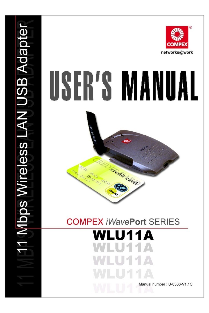
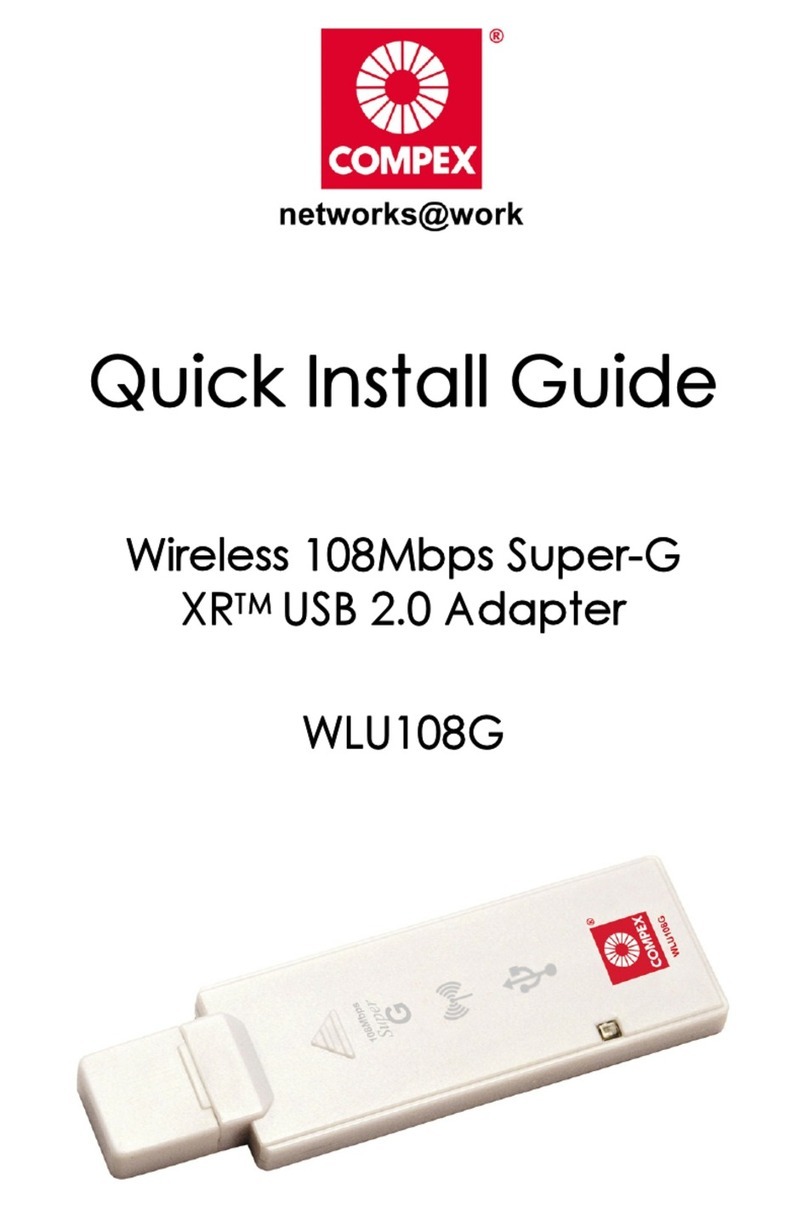
Compex WAVEPORT WL11 User manual

“Quick Install Guide”
Compex
WavePort
11Mbps Wireless LAN
PCMCIA Adapter
WL11
Version 1.1C
WAVEPORT

Contents
English Version Page 1-17
1. Chapter 1: Introduction Page 1
1.1 Description Page 1
1.2 WavePort Network Scenarios Page 1
A. Ad-hoc Wireless Workgroup Page 1
B. Stand Alone Wireless LAN Page 2
1.3 Features for Compex WavePort/WL11
Adapter Page 2
1.4 Quick Installation for Compex
WavePort/W11 Page 3
Card Removal and Re-insert Page 3
qPlug & Play Compatible Systems Page 4
qSystems That Do Not Support Plug
& Play Page 5
2. Chapter 2: Windows Installation Page 6
2.1 Installation Procedure Page 6
2.1.1 Windows NT V4.0 Installation
Guide Page 6
2.1.2 Windows 98 Installation Guide Page 7-8
3. Chapter 3: Configuration Utility Page 9-17
German Version Page 1-18
Russian Version Page 1-19
French Version Page 1-17
Technical Support Last Page
Notes

English Compex WavePort WL11 1
“Quick Install Guide”
Compex WavePort 11Mbps Wireless LAN PCMCIA
Adapter (WL11)
Chapter 1: Introduction
1.1 Description
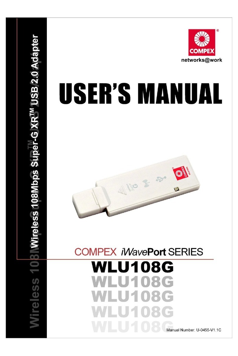
Thank you for purchasing the Compex 11Mbps WLAN PCMCIA Adapter (WL11).
Compex WavePort/WL11 is a plug-and-play PC card for notebook computers and
complies with the PCMCIA TYPE II standard. Integrated the antenna in, the 11Mbps
Wireless LAN PC card is optimized for low power consumption, high speed, high
security and high efficiency. It enables hot-desking and other forms of flexible offices
created in a matter of minutes.
1.2 WavePort Network Scenarios
This WavePort/WL11 PC Card enables you to:
•Connect your computer to an ad-hoc workgroup of wireless computing devices, or
•Connect your computer to a Local Area Network (LAN) infrastructure through
Compex WavePort/AP11 access point.
A. Ad-hoc Wireless Workgroup
Figure 1-1 Ad-hoc Wireless Workgroup
The ad-hoc workgroup configuration enables you to quickly set up a small
wireless workgroup participants can exchange files using features like “Files and
Printer Sharing” as supported by Microsoft Networking.

2Compex WavePort WL11 English
B. Stand Alone Wireless LAN
Figure 1-2 Stand Alone Wireless LAN
•Local Area Network (LAN) infrastructures may be:
Stand-alone wireless LANs as shown in figure 1-2.
With the presence of Compex Wave Port/AP11 Access Point, All communication is
done via the AP11, which relays packets to other wireless clients in the basic services
set as well as to nodes on the Ethernet network.
1.3 Features for Compex WavePort/WL11 Adapter
•High-speed wireless connection , up to 11 Mbps
•Comply with IEEE 802.11/802.11b (DSSS) standard
•Supports full mobility and seamless roaming from cell to cell
•Connect Utility software included
•Plug-and-play installation
•Advanced security features
•Option external antenna for super long distance connection
•Uses 3.3VDC power supply helps conserve power on the notebook.

English Compex WavePort WL11 3
a. Integrated Antennas
b. Transmit/Received
activity and Link
§Off- No wireless activity
or Link
§Blinking-
Sensing/transmitting
wireless data
§Solid Green- Link to other
WLAN Device.
1.4 Quick Installation for Compex WavePort/WL11
Insert the WL11 Adapter into a free CardBus slot, click through all the Windows
screens and use the drivers from the installation disk to finish the installation, follow
chapter 2 for details.
**Note: WL11 is designed to install in PCMCIA slot that support 3.3VDC. One
expample is a CardBus.
Card Removal and Re-insertion
WL11 adapter can be installed on various operating systems that may show different
behavior.
qPlug & Play Compatible Systems
qSystems That Do Not Support Plug & Play
Hot Plug is supported on Microsoft Wondows Oses like Windows 98 and Windows
2000.
a
b

4Compex WavePort WL11 English
qPlug & Play Compatible Systems
Plug & Play for WavePort PC Cards is supported by the following operating
systems:
§Windows 98 and Windows 2000 (formerly know as Windows NT v5.0)
When re-inserting the WavePort PC CARD into your computer, these
operating systems will automatically:
1. Recognize the card
2. (Re-) loads the driver and activates card operation.
3. Attempt to restore the network connection.
When removing the card, these operating systems will:
1. Disable WL11 driver and
2. Disconnect it from to the PC Card slot.
Note: When removing the WL11 adapter you will lose your connection on
the network.
Certain network operating systems however may not allow you to restore the
network logon automatically. In that case you may need to restart your
computer to rerun the network login procedure to restore the network
connection.
You are advised to always use the PC Card prior to removing the card utility
from the PCMCIA slot. This will allow the Windows operating system to
log off the network server, disable the driver properly and disconnect power
to the PCMCIA.
For example to stop the WavePort/WL11 adapter in MS-Windows
environment proceed as follows:
1. Click the “Start” button on the Windows Taskbar.
2. Click on “Settings” and then “Control Panel” item.
3. On the Control Panel double-click the PC Card icon to open the PC
Card (PCMCIA) properties window.
4. Select the PC Card socket that contains your WavePort/WL11 adapter
11 Mb PC Card and click the “Stop” button.
5. Wait for the operating systems to acknowledge that the device has
been disabled and then remove the PC Card from the PCMCIA slot.
English Compex WavePort WL11 5
Note: A shortcut to disable the PC Card is clicking once on the PC Card icon
on the right side of the Windows Taskbar, and select the option “Stop
WavePort/WL11 adapter”.
Double clicking the PC Card icon will open the PC Card properties
windows.
qSystems That Do Not Support Plug & Play
Although Windows 98 and Windows NT version 4.0 are from Microsoft,
only Windows 98 and Windows 2000 are true “Plug & Play”.
To remove or (re) insert your WavePortIWL11 adapter from these systems,
you are advised to:
1. Power off your computer.
2. Remove the WavePort/WL11 PC Card from the PCMCIA slot.
3. (Optional) Restart the computer to proceed working with your
computer without the WavePort/WL11 adapter.

6Compex WavePort WL11 English
Chapter 2 : Windows Installation
Note: Check that the PCMCIA device driver is started in Windows NT v4.0 before you
install the WL11 adapter.
These installation steps assumed you have Windows NT v4.0 already installed in your
notebook.
Please ensure the WL11 adapter is inserted in the notebook before power on.
2.1 INSTALLATION PROCEDURE:
2.1.1 WINDOWS NT V4.0 INSTALLATION GUIDE
A. Hardware Requirements
Notebook must be equipped with TYPE II PC card
Socket and support 3.3VDC power supply e.g. CardBus slot.
B. Firmware Requirements
Fully compliant with Rev. 2.1 or above PCI BIOS supplied with the PC.
C. Software Requirements
PCMCIA driver is required and service enabled.
D. Installation Procedure
1) Open the Control Panel, and choose Network Settings
double click on it.
2) Click the Add Adapter button to add new network
adapter. A list of network adapters will display. as
WL11 is a new adapter and will not be on the list. Go to
step 3.
3) Click on [OTHER] button to select driver not found in
Windows default list of network adapters.
4) Type in the drive and path, A:\ and click NEXT.
5) "Compex WavePort/WL11 PCMCIA Adapter" selection will
display. Select it.

English Compex WavePort WL11 7
6) Now you need to select IRQ Number and an I/O Base. You
can us Windows NT diagnostics to check the available
resources. (Start àprogram àAdministrative Tools
àWindows NT Diagnostics and select resource table.) Leave
those used resources out of your choice. Select a used IRQ
and an I/O Base for the WL11 card and click <OK>.
7) Windows will start to copy and installation of the
driver.
8) Click on OK when completed
9) Windows will prompt to restart the notebook.
2.1.2 WINDOWS 98 INSTALLATION GUIDE:
1. Insert the WL11 Adapter into the notebook PCMCIA slot.
Windows Add Hardware Wizard will automatically detect and found
a new device. The Add Hardware Wizard box will displays the
hardware device name. Please Click NEXT.
2. Windows then lets you select one of the following;
•Search for the best driver for your device (Recommended) or
•Display a list of all the drivers in the specific location so you can select
the driver you want.
Chose the first one and click NEXT,
3. Windows then let you mark on one or more of the following
•Floppy Disk Drive
•CR-ROM
•Specify a location
Check on Floppy Disk Drive and click NEXT,
•Note: Before you click NEXT, insert Compex WavePort/WL11
PCMCIA Adapter Driver disk in drive A
4. Windows will find the PCMCIA device and display the following:
"Compex WavePort/WL11 PCMCIA Adapter"
Click NEXT, to start copies the driver.

8Compex WavePort WL11 English
5. When completed copying the related files. Windows will prompt
to Restart the machine.
Click YES if you do not intend to add additional clients
and protocols.
By default, Windows 98 install only the following;
•Client for Microsoft Network
•Compex WavePort/WL11 PCMCIA Adapter
You may add NETBEUI and/or IPX/SPX protocols.
If you have a NetWare server add Microsoft for NetWare client.
Go to Control Panel | Network applet and add these protocols
and clients.
If you share your machine resources, add Files and Printing
share services.
Refer to Windows documents for further details.
6. When completed, Windows will again prompt to restart the machine.
Click YES.
7. When Windows rebooted, Compex WL11 PCMCIA Adapter is ready
to access the network.
**Note : For further customized configuration, refer to the Configuration Utility guide.

English Compex WavePort WL11 9
Chapter 3 : Configuration Utility
♦
COMPEX WavePort/WL11 PCMCIA uses his own management software.
All functions controlled by user are provided by this application. Usually
this application starts automatically, Use Start, Programs, WL11 LAN to
start the Manager application.
A new icon should appear in your Icon tray. If the icon is mark with red
“X” , it mean that WL11 LAN configuration is invalid or incomplete.
Sometimes icon can be colored in red. This can happen when driver is in
Pseudo BSS mode, and the radio channel, which is used for communication
is defined incorrectly.
♦
Clicking on that icon will show you the screen as shown below.
Figure 1 Management window with “Status” tab open
♦
User can navigate through “sheets”, by clicking or tapping them with stylus.
“OK” button will minimize window, and “exit” (or “X” button) will close
application. Here we explain the use and meaning of the various screen
messages.

10 Compex WavePort WL11 English
The first three fields show your wireless LAN card state.
Link status
– indicates link accessibility. There are several values, that can
be shown in the this part of the widow:
1.
Associated – BSSID=…
- normal flow of operation in Infrastructure
mode. The PC is connected to access point.
BASSID
is shown in the
form of HEX digits. Networking is available.
2. No status…
- the manager is retrieving information from the driver. If
this text box value stays more than several seconds, it means that there
are no access points or other workstation (if communicating in AdHoc
mode), or that the WL11 LAN card is plugged out the PC.
3. Scanning for access point -
driver scan wireless network searching
for available access point in Infrastructure mode.
4. Disabled or disconnected –
If this text box value stays more than
several seconds, it means that there are no access point or other
workstations (if communicating in Pseudo BSS mode), or that the
WL11 LAN Card is plugged out of PC.
5. Undefined – means critical driver error. This error is usually caused by
hardware misconfiguration (for example the card with similar chipset
inserted in PC card tray, but not fully compatible with COMPEX).
♦
Clicking on that icon will show you the screen as shown below.
Figure 1 Management window with “Status” tab open
♦
User can navigate through “sheets”, by clicking or tapping them with stylus.
“OK” button will minimize window, and “exit” (or “X” button) will close
application. Here we explain the use and meaning of the various screen
messages.

English Compex WavePort WL11 11
The first three fields show your wireless LAN card state.
Link status
– indicates link accessibility. There are several values, that can
be shown in the this part of the widow:
6.
Associated – BSSID=…
- normal flow of operation in Infrastructure
mode. The PC is connected to access point.
BASSID
is shown in the
form of HEX digits. Networking is available.
7. No status…
- the manager is retrieving information from the driver. If
this text box value stays more than several seconds, it means that there
are no access points or other workstation (if communicating in AdHoc
mode), or that the WL11 LAN card is plugged out the PC.
8. Scanning for access point -
driver scan wireless network searching
for available access point in Infrastructure mode.
9. Disabled or disconnected –
If this text box value stays more than
several seconds, it means that there are no access point or other
workstations (if communicating in Pseudo BSS mode), or that the
WL11 LAN Card is plugged out of PC.
10. Undefined –
means critical driver error. This error is usually caused
by hardware misconfiguration (for example the card with similar
chipset inserted in PC card tray, but not fully compatible with
COMPEX).
♦
Clicking on that icon will show you the screen as shown below.
Figure 1 Management window with “Status” tab open
♦
User can navigate through “sheets”, by clicking or tapping them with stylus.
“OK” button will minimize window, and “exit” (or “X” button) will close
application. Here we explain the use and meaning of the various screen
messages.

12 Compex WavePort WL11 English
The first three fields show your wireless LAN card state.
Link status
– indicates link accessibility. There are several values, that can
be shown in the this part of the widow:
11.
Associated – BSSID=…
- normal flow of operation in Infrastructure
mode. The PC is connected to access point.
BASSID
is shown in the
form of HEX digits. Networking is available.
12. No status…
- the manager is retrieving information from the driver. If
this text box value stays more than several seconds, it means that there
are no access points or other workstation (if communicating in AdHoc
mode), or that the WL11 LAN card is plugged out the PC.
13. Scanning for access point -
driver scan wireless network searching
for available access point in Infrastructure mode.
14. Disabled or disconnected –
If this text box value stays more than
several seconds, it means that there are no access point or other
workstations (if communicating in Pseudo BSS mode), or that the
WL11 LAN Card is plugged out of PC.
15. Undefined – means critical driver error. This error is usually caused by
hardware misconfiguration (for example the card with similar chipset
inserted in PC card tray, but not fully compatible with COMPEX).
•
Input byte/sec – shows the incoming (received) data speed, the progress bar
below, means receiver load.
•
Output byte/sec –
shows the outgoing (sent) data speed, the progress bar
below, show transmitter load.
•
Signal strength:
bar shows signal strength level. The higher blue bar is, the
more powerful is radio signal received by WL11. This indicator helps to
find the most comfortable antenna/workstation position for quality network
operation.
•
Link quality:
the measured signal level gives the overall Link Quality and
Connection Status.

English Compex WavePort WL11 13
“CONFIGURATION”tab
You can change the configuration by clicking on the
Change
Configuration.
When you click on the Change Configuration, you see the
screen given below.
Five changeable fields in the field show desired WL11 configuration.
The fields are below:
♦
Station ESS ID
Extended Service Set Identifier (Wireless Network
Identifier) is the group name that will be shared by every member of your
wireless network. You will only be able to connect with an
Access Point,
which has the same ESS ID.
♦
Network mode shows one of these network modes:
•Ad Hoc –this is the 802.11 peer-to-peer mode of operation. In Ad Hoc
only one wireless “cell”is supported for each different
ESS ID.
All
communication is done from Client to Client without the use of an
Access Point.
•
Infrastructure This mode of operation requires of an 802.11 Access
Point.
All communication is done via the
Access Point
, which relays
packets to other wireless Client in the BSS (Basic Service Set) as well
as to nodes on a wired network such as Ethernet.
♦
Ethernet Conversion
shows one of two different network packet forming
modes:
•
Encapsulated: This setting takes the entire Ethernet frame, including
the Ethernet Header, and puts it into an 802.11 frame. This setting is
here for compatibility with some older 802.11 implementations and
should not normally be used.

14 Compex WavePort WL11 English
•
RFC1042 where the DIX Ethernet frames are converted using SNAP
header based on RFC1042. This mode will also convert any RFC1042
SNAP header frames to DIX Ethernet frames before transmission to the
Ethernet interface.
•
802.1h where the DIX Ethernet frames are tunneled using a full
selective translation table. This mode does not convert RFC1042 SNAP
header frames to DIX Ethernet before transmission to the Ethernet
interface.
It is required to select encapsulation mode corresponding to the one your
access point or other workstations use. If the encapsulation mode is
incorrect, the PC will join to access point or will be seen by other
workstations, but network operation will not work.
♦
Channel –
show radio channel number for networking. Only Access Point
and Ad Hoc nodes can create a BSS therefore this parameters is not active if
Mode is Infrastructure. Infrastructure Client nodes will always go the same
channel as their AP. Please see the table for the requirements of different
countries and the channel frequency.
♦
TX Rate:
The transmission rate at which the data packets are transmitted
by the client or AP. You can see this to
Auto select or 2Mbps, Fixed 1Mbps,
Fixed 2Mbps, Fixed 5.5Mbps, Fixed 11 or Full Auto (1 to 11Mbps).
Important :
You must know the TX Rate that your AP can support.
Failure to which may cause the undesired results.

English Compex WavePort WL11 15
“ENCRYPTION”tab
You may desire an additional measure of security on your wireless network,
which can be achieved by using WEP (Wired Equivalent Privacy)
encryption. WEP encrypts each frame transmitted from the radio using one
of the Keys entered from this panel.
When an encrypted frame is received it will only be accepted if it decrypts
correctly. This will only happen if the receiver has the WEP Key used by
transmitter.
This panel allows the entry of four keys, which can then be written to the
driver and registry. Each key must consist of hex digits, it means that only
digit 0-9 and letters A-F are valid entries. If entered incorrectly program will
not write keys to a driver.
♦
Generate:These can generate the key for Key1 ~ Key4.
♦
Key 1 ~ Key 4: These four fields must be used to enter the keys.
♦
Write
: This button updates the driver with the four keys displayed in Key1
through Key4. The keys are also written the registry for permanent storage.
♦
Clear: This button clears all the bytes in the four keys, useful when entering
and you wish to start over.

16 Compex WavePort WL11 English
♦
Default Key:
This pop-up field defines one of the four keys which will be
used by the driver to encrypt frames it will be transmitting. This field does
not affect decryption, as the driver can decrypt any frame that it receives
which was encrypted with one of the four keys.
♦
Enable: This checkbox enables or disables encryption operation. When it is
checked, encryption is enabled, and when unchecked - encryption is
disabled. The corresponding action is written to a driver immediately.
“ABOUT”tab
Abort tab shows a software version. Users must use this version number
when reporting their problem to tech support.

English Compex WavePort WL11 17
Disclaimer: Compex, Inc. provides this guide without warranty of any kind, either expressed or
implied, including but not limited to the implied warranties of merchantability and fitness for a particular
purpose. Compex, Inc. .may make improvements and/or changes to the product and/or specifications of
the product described in this guide, without prior notice. Compex, Inc will not be liable for any
technical inaccuracies or typographical errors found in this guide. Changes are periodically made to the
information contained herein and will be incorporated into later versions of the guide. The information
contained is subject to change without prior notice.
Trademark Information:
Compex®, ReadyLINK®and MicroHub®are registered trademarks of
Compex, Inc. All brand and product names are trademarks or registered trademarks of their respective
owners.
Notice: Copyright ©1999 by Compex, Inc. All rights reserved. Reproduction, adaptation, or
translation without prior permission of Compex, Inc.is prohibited, except as allowed under the copyright
laws. Manual Revision by Jean Tan.
Manual Number: M-0300-V1.1C Version 1.1C, August 2000 Printed in Singapore
FCC NOTICE:
This device has been tested and found to comply with the limits for a Class A
digital device, pursuant to Part 15 of the FCC Rules. These limits are designed to provide reasonable
protection against harmful interference in a residential installation. This device generates, uses and can
radiate radio frequency energy and, if not installed and used in accordance with the instructions, may
cause harmful interference to radio communications. However, there is no guarantee that interference
will not occur in a particular installation. If this device does cause harmful interference to radio or
television reception, the user is encouraged to try to correct the interference by one or more of the
following measures:
g
g
Reorient or relocate the receiving antenna.
Connect the computer into an outlet on a
circuit different from that to which the
receiver is connected.
g
g
Increase the separation between the
computer and receiver.
Consult the dealer or an experienced
radio/TV technician for help.
Caution:
Any changes or modifications not expressly approved by the grantee of this device could void
the user's authority to operate the equipment.
FCC Compliance Statement: This device complies with Part 15 of the FCC Rules. Operation is
subject to the following two conditions:
(1)
(2) This device may not cause harmful interference, and
This device must accept any interference received, including interference that may cause
undesired operation.
DECLARATION OF CONFORMITY: Compex, Inc. declares that the product:
Product Name: Compex Waveport 11Mbps Wireless LAN PCMCIA Adapter Model
Number: WL11 conforms to the following Product Standards: FCC Part 15; ETS 300-826
General EMC requirements for Radio Equipment; ETS 300-328 Technical requirement for
Radio Equipment.
Manufacturer’s Name: Compex, Inc.
Address: 4051 E. La Palma, Unit A,
Anaheim, CA 92807, USA
European Contact:
ReadyLINK Networktechnology GmbH,
Technical Support
Albert Einstein Straβe 34 / M21,
63322 Rödermark, Germany
[Fax: +49 (60) 749-0668]
Singapore, August 29th, 2000
_________________
Mr Shi Jia Xiang
Deputy R & D Manager

German Compex WavePort WL11 1
“Installationsanleitung”
Compex WavePort 11Mbps Wireless LAN PCMCIA
Adapters (WL11).
Kapitel 11. Einleitung
1.1 Beschreibung
Wir danken Ihnen für den Kauf dieses Compex-WavePort 11Mbps- Wireless
LAN-PCMCIA-Adapters (WL11).
Der Compex Waveport WL11 ist eine Plug-&-Play-Karte für Notebook-PCs und
entspricht der PCMCIA-TYP-II-Norm. Mit der integrierten Antenne wurde die
11Mbps-PC-Karte für das kabellose LAN (lokale Netz) für eine niedrige
Stromaufnahme, hohe Betriebsgeschwindigkeit und Sicherheit sowie für eine
Maximalleistung optimiert. Sie ermöglicht ein Hot-Desking sowie weitere
Möglichkeiten für flexible Büroeinrichtungen, die nur innerhalb weniger Minuten
eingerichtet werden können.
1.2 WavePort-Netzwerk-Szenarien
Mit dieser WavePort/WL11 PC-Karte können Sie
•Ihren Computer an eine Ad-hoc-Arbeitsgruppe mit kabellosen
Computergeräten oder
•Ihren Computer an eine Infrastruktur eines lokalen Netzes (LAN) über den
Compex-WavePort/AP11-Zugriffspunkt anschließen.
A. Kabellose Ad-hoc-Arbeitsgruppe
Abbildung 1-1 Kabellose Ad-hoc-Arbeitsgruppe
Table of contents
Languages:
Other Compex Adapter manuals

Compex
Compex WLM54GP23 User manual

Compex
Compex WLM54AG Manual

Compex
Compex NetPassage WLM54AGP23 User manual

Compex
Compex iWavePort Series User manual

Compex
Compex HOMEPNA HP10 User manual

Compex
Compex LinkPort/TX32A User manual

Compex
Compex WLP54G 3a User manual

Compex
Compex RL1000T User manual

Compex
Compex WLM54AG User manual

Compex
Compex UE202-B User manual