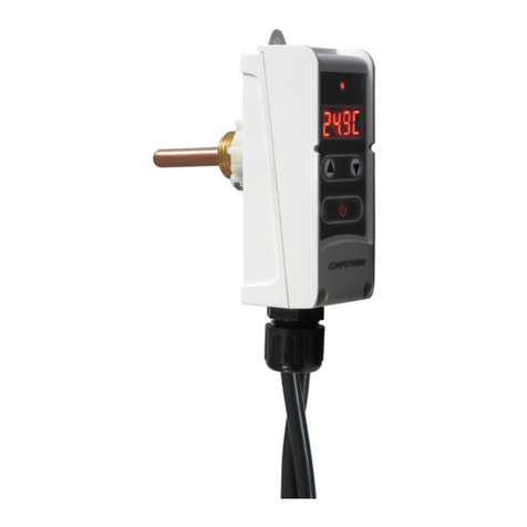
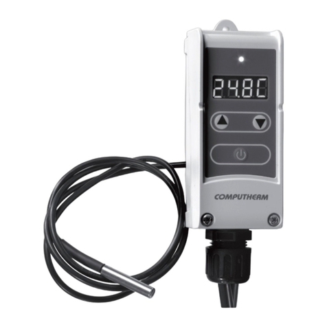
Computherm KonvekPRO User manual

COMPUTHERM
KonvekPRO
Gas convector controller
Operating Instructions

- 2 -
A GENERAL DESCRIPTION OF THE
GAS HEATER CONTROLLER
The
COMPUTHERM
KonvekPRO type gas heater
controller is able to control the vast majority of the
gas heaters available on the Hungarian market. It
can easily be connected to any gas heater which
regulates its own operation with a removable
probe of the thermostat of the gas heater (a copper
cartridge containing the expanding uid connected
to the thermostat with a capillary tube).
To establish the control system a two-wire room
thermostat should be connected to the appliance.
On demand the appliance can be controlled by
integrating it into a smart home system. By warming
up the probe of the gas heater it “deceives” the gas
valve of the gas heater which shuts o and does
not heat.
When the temperature in the room goes below
the value set on the room thermostat then, based

- 3 -
on the signal received from the room thermostat,
KonvekPRO stops heating the tube thermostat of the
gas heater which cools down (for 3-6 minutes) below
the temperature value set by the regulating knob of
the gas heater so the gas heater switches on and
starts to heat. When the temperature in the room
reaches the value set on the room thermostat then
the room thermostat sends a signal to KonvekPRO
to warm up (for 1-1.5 minutes) the tube thermostat
above the value set by the regulating knob of the
gas heater and the gas heater stops heating.
Using KonvekPRO an automatic programmed
heating system can be easily established in a
room heated by gas heater. Besides, this product
enables you to control your gas heaters remotely by
using a Wi-Fi thermostat. With this product you can
save considerable energy in addition to improved
comfort.
We have designed KonvekPRO for gas heaters only.
In Hungary gas heaters manufactured by FÉG

- 4 -
are used in the vast majority of households. The
appliance, however, can also be operated with
gas heaters of several other manufacturers (e.g.
Pelgrim, Lampart, Demrad, etc.) which contain a
tube thermostat (CR6 or EUROSIT 630 gas valve)
similar to that of FÉG types.
More than one gas heater can be controlled by
a single thermostat and as many KonvekPROs as
the number of the gas heaters you want to con-
trol. If you want to control your heating system
with a wireless room thermostat then you need
only 1 wireless room thermostat and 1 receiving
unit for every gas heater.
1. LOCATION OF THE APPLIANCES
The
COMPUTHERM
KonvekPRO gas heater control-
ler should be located near the gas heater, xed
preferably to a wall at such a distance from the
gas heater so that the metal probe therein can be
connected to the controller. The room thermostat

- 5 -
is connected to KonvekPRO with 2 wires therefore it
should be located at a distance that allows you to
connect it and its location is accessible for adjust-
ment. If you want to control KonvekPRO with a wire-
less thermostat then it is recommended that you
locate the receiving unit of the thermostat in the
vicinity of KonvekPRO. In this case the thermostat
can be moved anywhere within the range.
IMPORTANT WARNING! For proper operation of
the gas heater controller turn the temperature
regulating knob in the gas heater to approx.
30 °C (in case of FÉG products it is grade 6-6.5
on a scale to 7).
2. PUTTING THE GAS HEATER
CONTROLLER INTO SERVICE
Warning! The appliances must be put into
operation by a competent person!
WARNING! Any modication of the appliance
poses a risk of electric shock or failure.

- 6 -
2.1. Get the things included in the package of
COMPUTHERM
KonvekPRO ready: appliance
KonvekPRO, PSU, 2 dowels and 2 screws. You
will also need a pencil, a drilling machine,
small (athead and Phillips) watchmaker’s
screwdrivers, a Ø6 mm drill bit and, maybe,
a hammer.
2.2. Carefully lift out the probe on the back side of
your gas heater from its socket. The probe is
normally located on the back side of the gas
heater, in rare cases it is beneath the cover
at the end of an approx. 50 cm long copper
pipe.
2.3. Find some place suitable for xing KonvekPRO
in the vicinity of the gas heater (wall, window
frame), considering the length of the copper
pipe that connects the gas heater and the
probe.

- 7 -
Put the template to the place
where you want to install
KonvekPRO. Then perforate the
template in the middle of the
circles indicated by the arrows
by means of a pencil.

- 8 -
It is expedient to nd a place where KonvekPRO
is exposed to radiant heat (from the gas
heater) to the smallest extent possible. With
the help of the actual size template shown on
the previous page mark the hole locations for
xation.
2.4. Prepare the holes (Ø6 mm), put the dowels
and screws into them so that 3-4 mm of the
screws protrudes from the wall.
2.5. Insert the probe of the gas heater carefully
into the KonvekPRO. The probe receiving
socket of the KonvekPRO is universal and able
to receive a Ø6-12 mm probe. When insert-
ing the probe, make sure that the probe is
always inserted perpen-
dicularly to KonvekPRO,
oriented to its right lower
side viewed from the front
so that it ts in the hole on
the other (upper) side.

- 9 -
2.6. Place KonvekPRO onto the screws prepared on
the wall and, with a cautious vertical motion, x
it in place. In case of correct installation Konvek-
PRO is seated stably against the wall surface.
2.7. Connect the cable leading to the thermostat
to KonvekPRO. Put a thin two wire cable into
the thermostat connector located in the lower
part of KonvekPRO then tighten the fastening
screws with a small watchmaker’s screwdriver,
reaching through the holes on its top.
Several KonvekPRO can be combined and
connected to a single thermostat but in this
case you should ensure correct polarity: in
this case make sure that the right-hand side
cable of each thermostat connector located
on KonvekPROs to be combined is connected
to the connector on the right side of the other
KonvekPROs while left cables are connected
only to left connectors.
2.8. Install the thermostat (which is compatible only

- 10 -
if it has a potential free make/break contact)
according to the instruction manual provided
with it and connect it to KonvekPRO with the
pair of wires (to connection points 1 /NO/
and 2 /COM/ for
COMPUTHERM
room ther-
mostats). For the RF type you should also
connect a 230 V cable to points N and L of
the receiving unit. In general it is expedient
to locate the thermostat on the wall of a room
where you stay regularly or a long period of
time so that the thermostat is oriented in the
direction of the natural ventilation of the room
but is not exposed to draught or extreme heat
(e.g. sunlight, refrigerator, chimney, etc.). Its
optimal location is at a height of 1.5 m from
the oor.

- 11 -
The following gure shows the control system for
gas heaters:

- 12 -
If you want to control several gas heaters with a
single thermostat you can choose between the
following connection alternatives:

- 13 -

- 14 -
2.9. Turn the temperature regulating knob on
your gas heater up to 30 °C (in case of FÉG
products it is grade 6 on a scale to 7).
2.10.
Connect the mains power supply unit
provided in the unit packet to KonvekPRO
and energize it.
2.11.
Put KonvekPRO into AUTO mode with the slide
switch on the top of the appliance. The light
of the orange-color LED on the top of the
appliance provides feedback on automatic
operation of KonvekPRO.
Warning! If you do not switch on KonvekPRO the
gas heater will heat the room to the temperature
set on its own temperature regulator (to approx.
31 °C in case of grade 6.5), irrespective of the
temperature set on the room thermostat. After
KonvekPRO is turned on, the appliance will control
the operation of the gas heater based on the
temperature set on the room thermostat.

- 15 -
Cable
fastener
used to
connect
thermostat
Power connector Calibration
slot
Thermostat
connector
Receiving socket
for temperature
sensor probe

- 16 -
3. OPERATING MODES OF THE
GAS HEATER CONTROLLER
You can switch between control modes of the
gas heater with the slide switch on the top of the
appliance. The controller has the following modes:
• Manual mode (MAN; left position of the slide
switch):
In manual mode of the controller the gas heater
works fully independently from KonvekPRO and
the thermostat connected thereto. In such case
the gas heater works in the traditional way
and can be controlled with the temperature
regulating knob therein instead of the
thermostat.
• Automatic mode (AUTO; right position of the
slide switch):
In automatic mode of the gas heater is controlled
automatically according to the settings of the
thermostat connected to KonvekPRO.

- 17 -
The gas heater will heat when the thermostat
gives a heat command.
4. MEANING OF THE SIGNS OF
THE CONTROL LED OF THE GAS
HEATER
The operating status of the gas heater controller
is indicated by the lights of the orange and blue
LEDs on the upper side of the device as follows:
• When the slide switch is „MAN” position on the
left side:
o When the blue LED is on then the controller
works in manual mode.
o When neither LED is on then power is not
supplied to the controller.
• When the slide switch is „AUTO” position on
the right side:
o When the blue LED is on then the thermostat
gives heat command and the gas heater is
heating.

- 18 -
o When the orange LED is on then there is no
need for heating according to the settings
of the thermostat. Then the gas heater
controller warms the temperature sensor
probe of the gas heater with the result that it
does not heat.
o When neither LED is on then there is no
need for heating according to the settings of
the thermostat. The controller has already
warmed up suciently the temperature
sensor probe of the gas heater so that that
the gas heater does not heat and it does not
warm currently.
5. ADJUSTMENT OF THE GAS
CONVETOR CONTROLLER
No subsequent adjustments of KonvekPRO are
normally necessary since these were carried out
before shipment. If you deem that the operation of
the device is unstable please follow the instructions
below.

- 19 -
5.1. After you have completed installation, set the
connected digital thermostat temporarily to a
temperature considerable lower than that of
the room to prevent it from switching the gas
heater on.
5.2. Turn the temperature regulating knob of the gas
heater to minimum setting (pilot ame).
5.3. With the orange LED thereon KonvekPRO indi-
cates that it works and has started to heat the
probe incorporated therein. When the LED goes
out, the probe reached the temperature set on
KonvekPRO. After a few minutes the LED is on
then goes out again to keep the temperature
at this value. This target temperature (switch-
ing threshold value) is set to approx. 30 °C
by the manufacturer and this is suitable in the
overwhelming majority of cases. But if not, with
a screwdriver you can increase (clockwise) or
decrease (anticlockwise) this threshold value in

- 20 -
the range between 25 °C and 35 °C through the
calibration slot at the bottom of KonvekPRO.
5.4. Wait 20 to 30 minutes so that the system
assumes its operating temperature.
5.5. Turn the temperature regulating knob of
your gas heater very slowly towards higher
temperatures. When the switching threshold
value set on KonvekPRO is reached the gas
heater ignites. This probably will happen near
the maximum grade. If the gas heater fails to
ignite then it means KonvekPRO has heated the
probe above the temperature limit that can be
sensed by the gas heater. It does not present
any problem just the response time of the
system (the period of time that elapses between
the arrival of the heat command coming from
the thermostat and the actual point of time
when the gas heater switches on) is increased
somewhat.
Table of contents
Other Computherm Controllers manuals