- 5 -
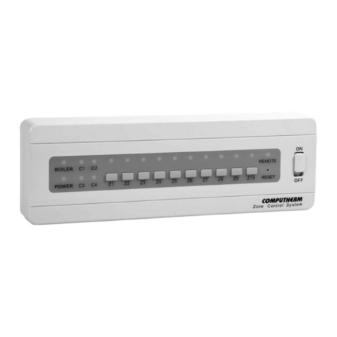
• The 1st and 2nd zones, beside their regular connection points, also have
a joint connection point for a zone valve/pump (Z1-2). If any of the 1st two
thermostats (T1 and/or T2) switches on, then beside the 230 V AC voltage
appearing at Z1 and/or Z2, 230 V AC voltage appears on Z1-2 too, and the
zone valves/pumps connected to these connection points open/start. This Z1-2
connection point is suitable to control the zone valves/pumps in such rooms
(e.g. the hall or the bathroom), which do not have a separate thermostat, do not
need heating at all times but need heating when any of the 1st two zones heat.
• The 3rd and 4th zones, beside their regular connection points, also have
a joint connection point for a zone valve/pump (Z3-4). If any of the 2nd two
thermostats (T3 and/or T4) switches on, then beside the 230 V AC voltage
appearing at Z3 and/or Z4, 230 V AC voltage appears on Z3-4 too, and the
zone valves/pumps connected to these connection points open/start. This Z3-4
connection point is suitable to control the zone valves/pumps in such rooms
(e.g. the hall or the bathroom), which do not have a separate thermostat, do not
need heating at all times but need heating when any of the 2nd two zones heat.
• Moreover, the four heating zones also have a joint connection point
for a zone valve/pump (Z1-4). If any of the four thermostats (T1, T2, T3
and/or T4) switches on, then beside the 230 V AC voltage appearing
at Z1, Z2, Z3 and/or Z4, 230 V AC voltage appears on Z1-4 too, and the
pump connected to output Z1-4 also starts. This Z1-4 connection point is
suitable to control the heating in such rooms (e.g. the hall or the bathroom),
which do not have a separate thermostat, do not need heating at all times but
need heating when any of the four zones heat. This connection point is also
suitable for controlling a central circulating pump, which starts whenever any
of the heating zones starts.
• There are some zone valve actuators that need a x phase, a switched
phase and a neutral connection to operate. The connection points of the x
phase are next to the (POWER INPUT) indicated by the FL FL sign. The
connections of the x phase are only operating when the power switch is
turned on. Due to the lack of space there is only two connection points. By
joining the x phases four actuators can be operated.
• The 15 A fuse on the right side of the power switch protects the components
of the zone controller from electrical overload. In case of overloading the
fuse cuts o the electric circuit, protecting the componets. If the fuse has cut
o the circuit, check the appliances connected to the zone controller before


